
ENVIRONMENTAL CONTROL SYSTEM
Environmental Control System Diagram
Primary and Secondary Oxygen System Diagram
Cabin Environmental Control Schematic
Suit Loop Recirculation Mode Schematic
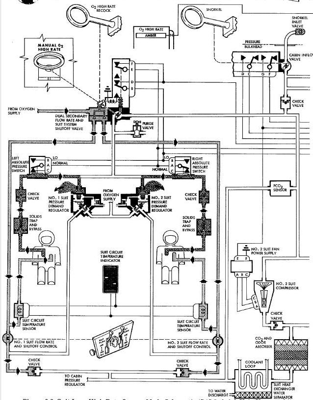
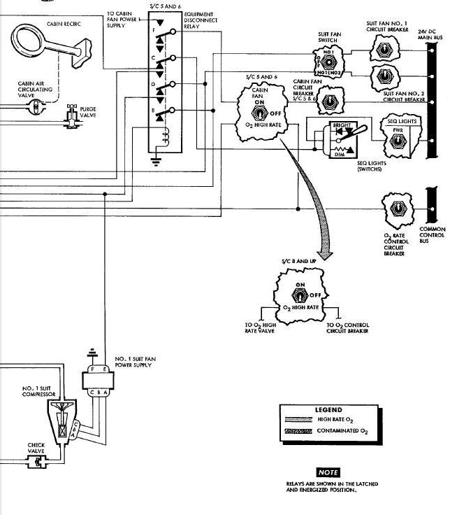
Suit Loop High Rate Oxygen Mode Schematic
Suit Loop High Rate Oxygen Mode Schematic
Water Management System Diagram
Water Management System Schematic
SECONDARY OXYGEN SHUTOFF Handle
CABIN And P C02 PRESS Indicator
ECS 02 QUANT % and PSIA (CRYO) Meter
DUAL SECONDARY OXYGEN RATE AND SUIT SYSTEM SHUTOFF VALVE
Suit Oxygen Demand Regulator Diagram
PRIMARY SUPERCRITICAL OXYGEN CONTAINER
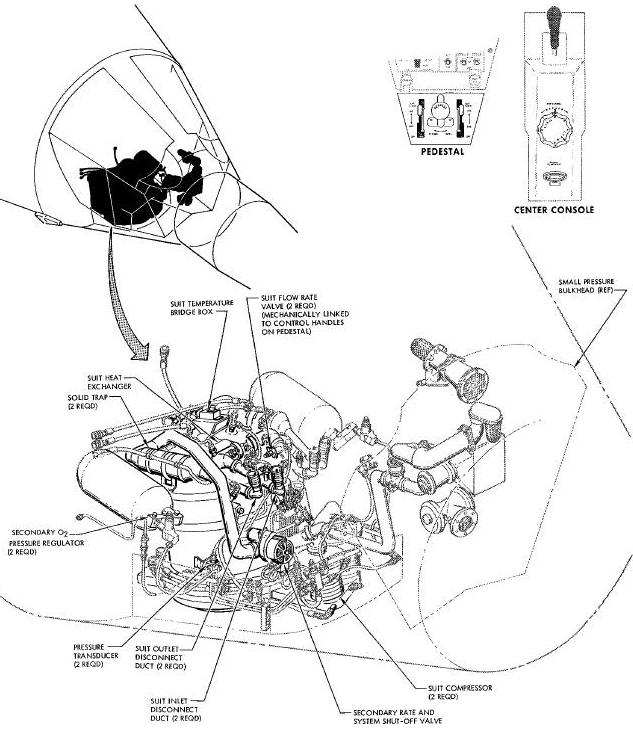
Environmental Control System Diagram
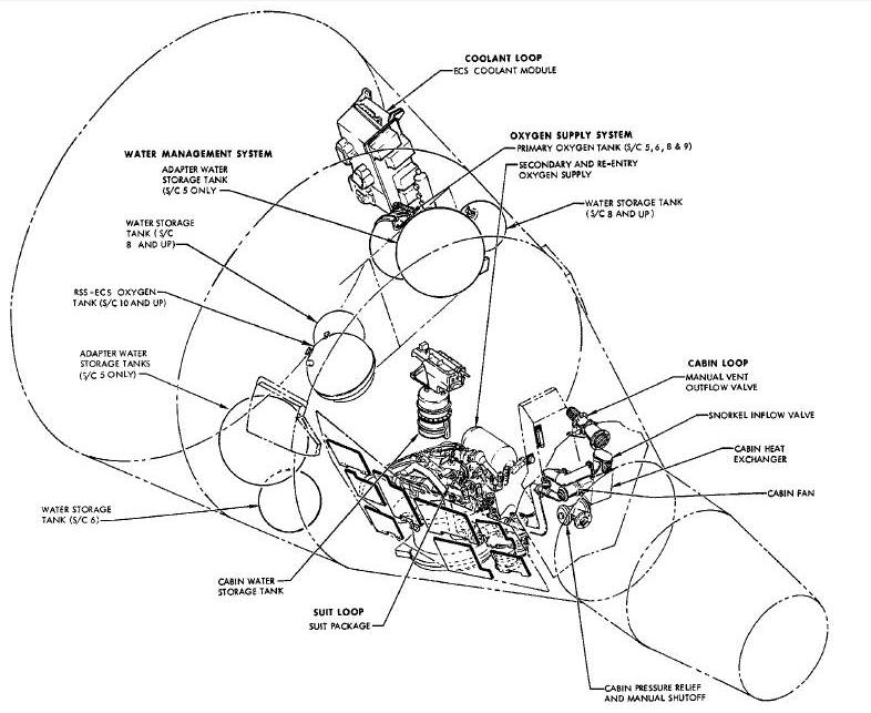
The Environmental Control System (ECS) may be defined as a system which provides a safe and comfortable gaseous atmosphere for the pilots. The system must perform such tasks as providing fresh oxygen, pressurization, temperature control, water removal and toxic gas removal. In addition to providing atmospheric control for the pilots, the system provides equipment cooling and regulated temperatures for certain pieces of equipment.
For ease of understanding, the Environmental Control System may be
separated into four systems or loops which operate somewhat independent
of each other. These loops are:
(1) The oxygen supply system.
(2) The cabin loop.
(3) The suit loop.
(4) The water management system.
There are three oxygen systems: Primary, Secondary and Egress.
This system stores and dispenses oxygen for breathing and for suit
and cabin pressurization.
This system provides oxygen during the period commencing two hours prior to launch and terminating with jettison of the adapter section at retrograde.
The primary oxygen supply is stored at supercritical pressure in a cryogenic spherical container in the adapter section of the spacecraft. This container is filled with liquid oxygen at atmospheric pressure. Heat is supplied by thermal leakage through the container insulation and by activation of an electric heater in order to build pressure to the critical point of 736 psia. Above this point liquid oxygen becomes a homogeneous mixture, described for simplicity as a dense supercritical fluid. This fluid is warmed, regulated and filtered before it enters the suit or cabin loop.
A long mission ECS oxygen tank will replace the short mission Reactant Supply System (RSS) oxygen tank and the ECS oxygen tank, allowing ECS breathing and the RSS oxygen to be stored in the same container. A tee fitting on the cryogenic line allows both the ECS and RSS systems to receive oxygen from the common container.
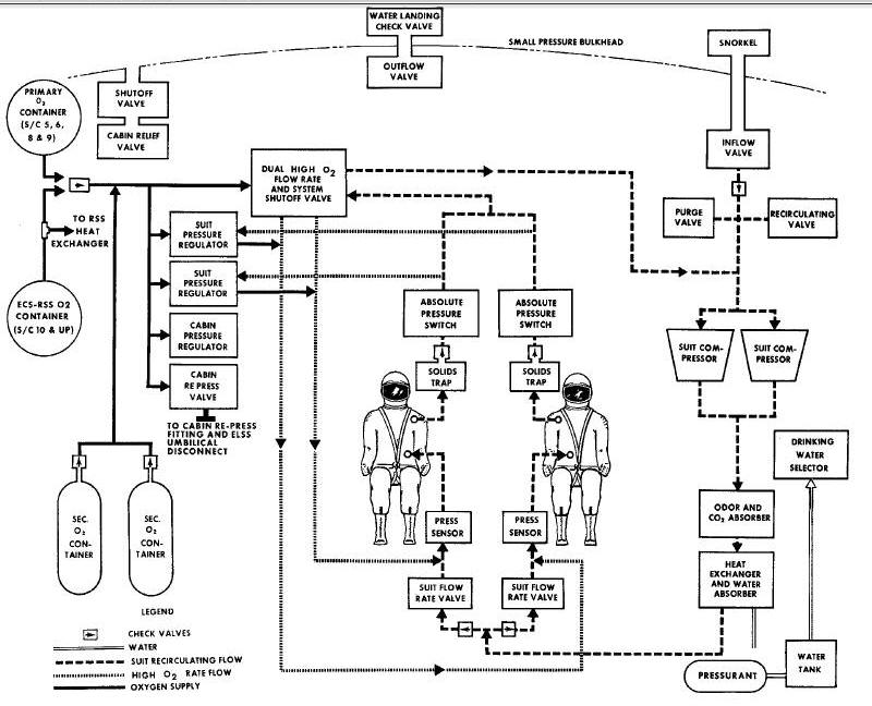
The primary loop consists of the following components: primary oxygen container, pressure control switch, pressure transducer, fill and vent valves, temperature discharge sensor, pressure relief valve, pressure regulator, shutoff valve, filter, check valves, and heat exchanger.
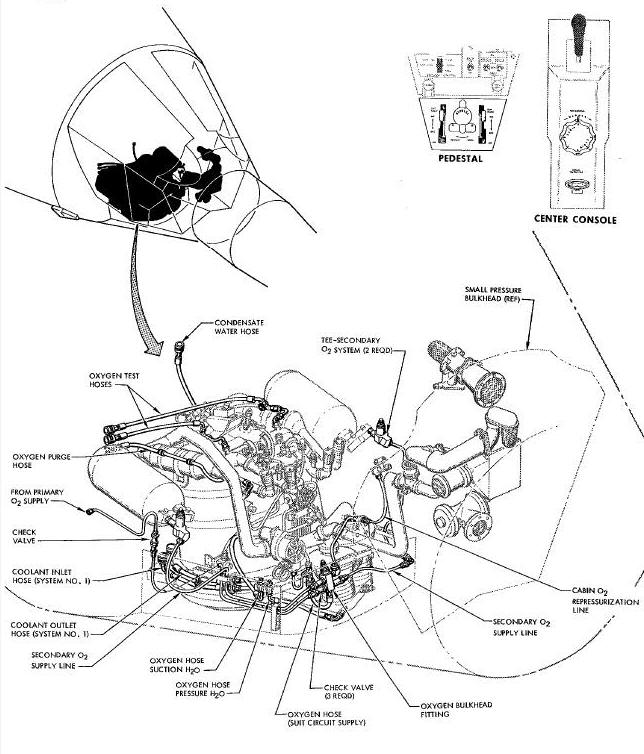
Primary and Secondary Oxygen System Diagram
The secondary oxygen system is capable of performing the same functions
as the
primary oxygen system and operates when pressure in the primary system
falls below 75 +/- i0 psi. At retrograde, when the primary oxygen container
is jettisoned with the equipment adapter, the secondary oxygen system
assumes the duties of the primary oxygen system.
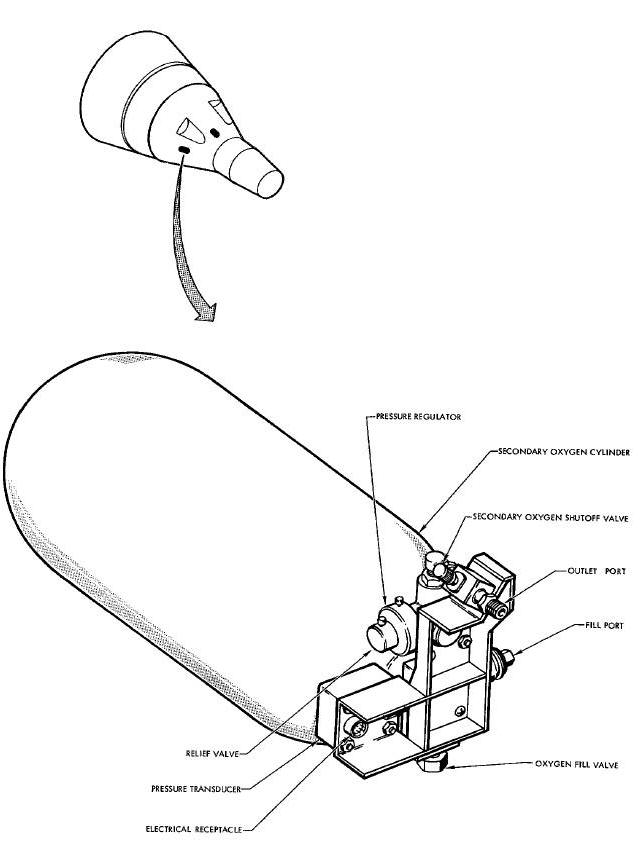
The gaseous secondary oxygen supply is stored in two cylinders located in the re-entry module. Each tank contains 6.5 pounds of usable oxygen pressurized to 5000 psig maximum at 70°F. This oxygen supply is then regulated before it enters the suit or cabin loop.
The secondary system consists of two: tanks, fill valves, transducers, pressure regulators, shutoff valves and check valves.
Cabin Environmental Control Schematic
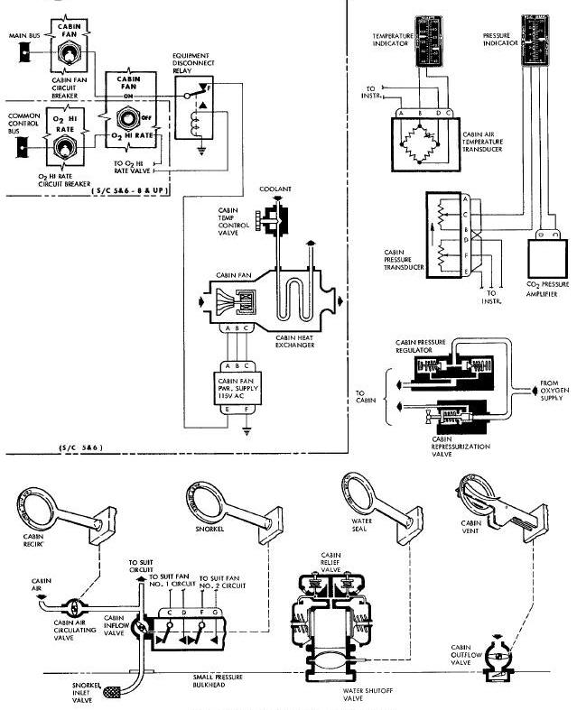
Design cabin leakage at ground test conditions is 670 standard cubic centimeters per minute, (scc/min) of nitrogen at 5.0 psig. Makeup oxygen, to maintain cabin pressure at nominal 5.1 psia level, is called for by the cabin pressure regulator. In order to obtain maximum utilization of oxygen, it first passes through the suit loop before it is dumped into the cabin through the suit pressure relief valves.
This loop contains a relief valve for both positive and negative pressure relief, a pressure regulator and manual valves to either dump cabin pressure or repressurize. In the latter operation, oxygen is supplied directly to the cabin.
The pilots are provided with redundant atmospheres by having a closed pressure suit circuit within the pressurized cabin. This suit circuit provides for cooling, pressurization, purification and water removal.
The suit loop is a closed system with two pressure suits operating in
parallel.
Circulation of oxygen through the suit is provided by a centrifugal
compressor. Carbon dioxide and odors are removed by an absorber
bed containing lithium hydroxide and activated charcoal. The gases are
cooled in a heat exchanger by a liquid coolant, Monsanto MCS 198, to a
temperature below the dew point. Water condensing within the heat
exchanger is dumped overboard or routed to the water evaporator. The
reconditioned Oxygen is mixed with fresh makeup oxygen.
The suit circuit has two modes of operation, the normal recirculation Node which was discussed in the previous paragraph and the high rate mode which shuts off the recirculation system and pumps oxygen directly into the suit.
Suit Loop Recirculation Mode Schematic
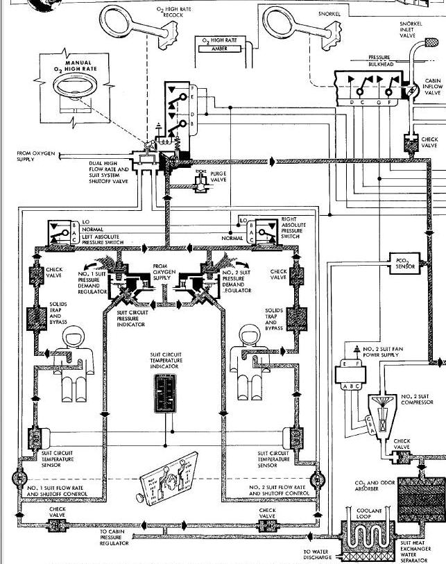
The suit loop consists of two suit pressure demand regulator valves, four check valves, two throttle valves, two solid traps, a system shutoff and high flow rate valve, two ccmpressors, one carbon dioxide and odor absorber, and a suit heat exchanger.
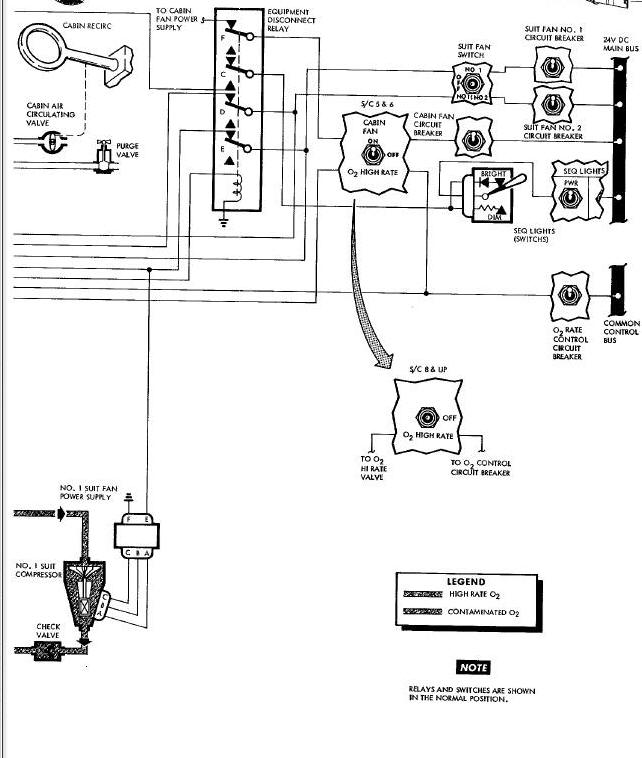
Suit Loop High Rate Oxygen Mode Schematic
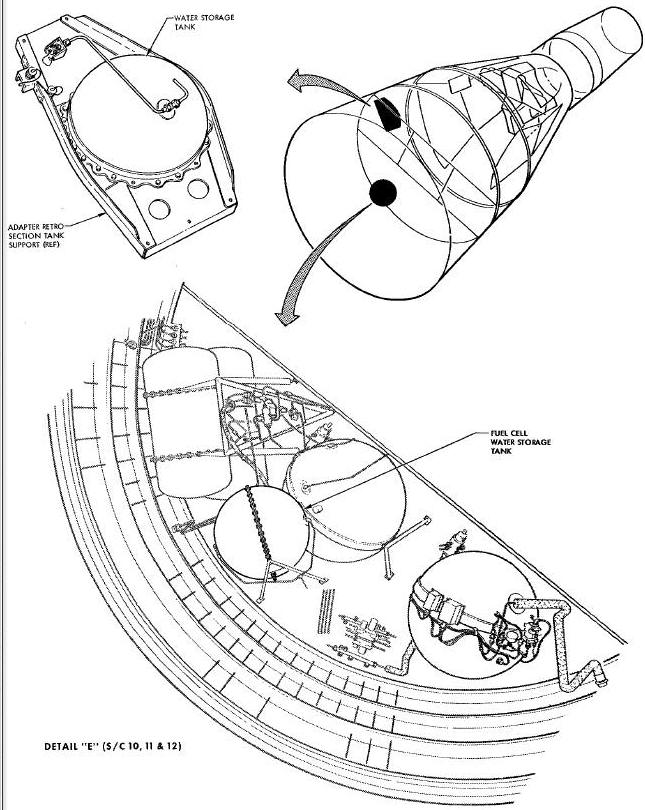
The purpose of the water management system is to store and dispense drinking water, collect and route unwanted water to the evaporator or dump overboard.
Water Management System Diagram
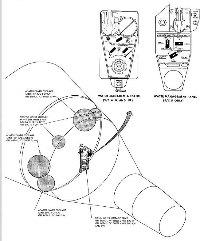
Drinking water is stored in a tank or tanks in the adapter. Each tank contains a bladder and is pressurized to supply water to the transparent tank in the re-entry module.
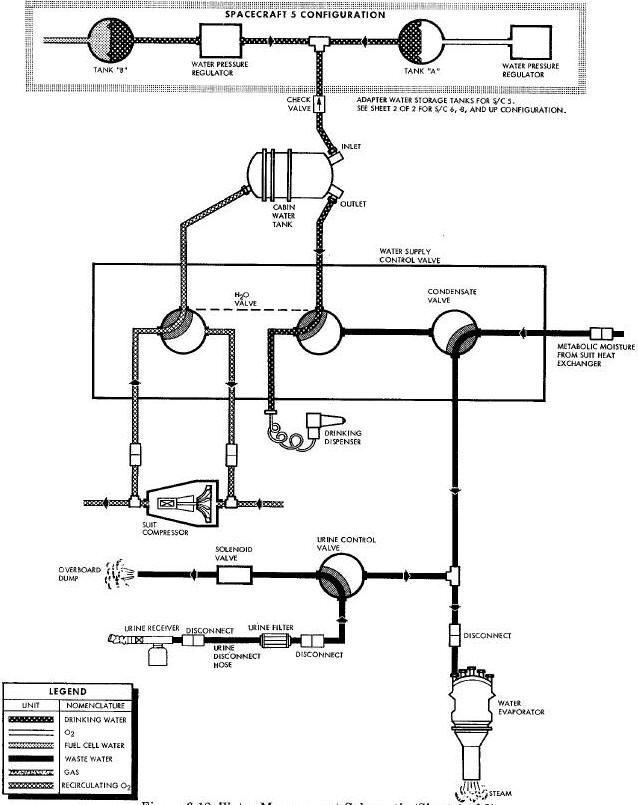
Water Management System Schematic
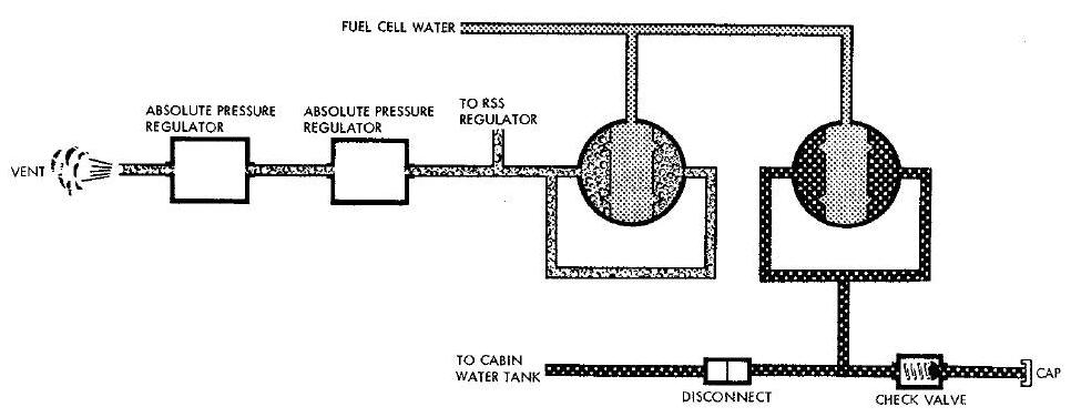
The Spacecraft utilizes two storage tanks. Fuel cell by-product
water is
used as the pressurant for the drinking storage tank. The other tank is
used to
store fuel cell water.
Urine and condensated water from the suit circuit heat exchanger is absorbed by the wick in the water boiler or dumped overboard.
Components of the water management system, in addition to the water tanks, are a water control valve, condensate valve, water evaporator and two manual shutoff valves.
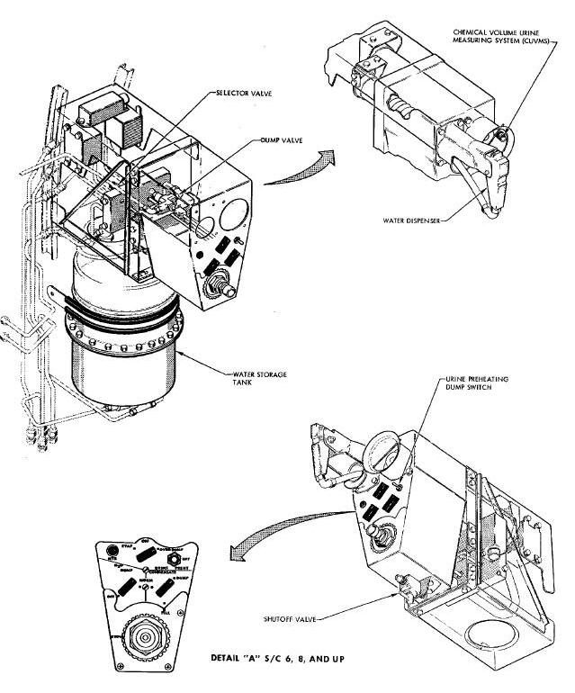
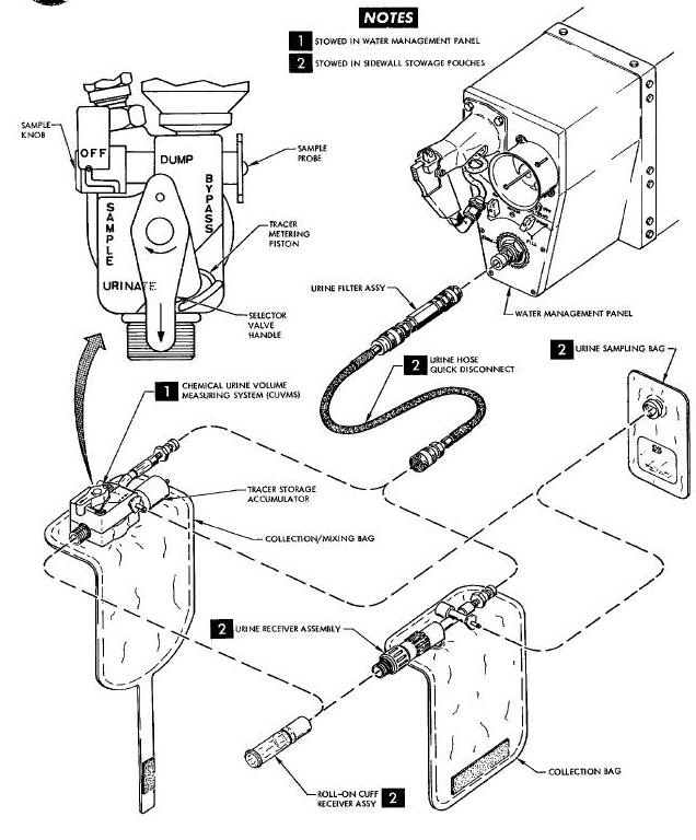
The urine system is designed for total management of the crewmens urinary output. It samples and determines total volume of every urination and provides for chemical analysis. Volume is determined by sampling every urination and using a tracer dilution technique. Three tenths (0.3) ml of tracer chemical is added to the urine and samples are taken. During postflight operations, the amount that the tracer has been diluted in each sample determines the quantity of urine voided by the crewmen. The urine system consists of the following components; a Chemical Urine Volume Measuring System (CUVMS) with selector valve, tracer storage accumulator and collection/mlxing bag, a urine receiver assembly with collection bag, a urine quick-disconnect hose and urine solids trap filter, urine sampling bags and a roll-on cuff receiver assembly.
The displays and controls for the Environmental Control System are provided in the cabin and function as specified.
SECONDARY OXYGEN SHUTOFF Handle
A manual secondary oxygen shutoff handle is provided for each member of the flight crew for complete and positive shutoff of each secondary oxygen container. The handles are located aft of the right and left switch/circuit breaker panels. The position OPEN or CLOSED is noted.
The 02 HI RATE telelight located on the instrument panel illuminates when the high oxygen rate valve is opened manually or automatically.
The cabin air recirculation handle controls the recirculation valve which permits entry of cabin air into the suit circuit for removal of odors and carbon dioxide. This procedure will renovate cabin air without cabin decompression and reduces the possibility of carbon dioxide pockets by increasing circulation of the cabin atmosphere.
This handle will control the cabin air inlet valve which provides for ventilation during landing and postlanding phases of the mission.
This handle controls the operation of the cabin outflow valve to permit emergency decompression in orbit and cabin ventilation during the landing phase.
This handle provides for watertight closure of the cabin pressure
relief valve
during a water landing.
0 2 HI RATE RECOCK Handle
This handle provides for the manual return of the oxygen high rate valve
to the closed position, thereby restoring normal oxygen flow rate.
Actuation of this handle also reestablishes the capability of initiating
high rate oxygen flow
when necessary.
A dual indicator provides for monitoring temperatures in the suit and cabin circuits. Range markings are calibrated in degrees Fahrenheit.
CABIN And P C02 PRESS Indicator
A dual indicator provides for monitoring cabin atmospheric pressure and the amount of carbon dioxide at the suit inlet. Cabin atmospheric pressure is calibrated in pounds per square inch. Carbon dioxide partial pressure is calibrated in millimeters of mercury.
A dual indicator is provide for monitoring pressure in the individual gaseous oxygen containers in the secondary oxygen subsystem. The indicator range is from O to 6000 psia, divided into 500-pound increments and numbered at each 1O00-pound interval. Readings must be multiplied by 100 to obtain correct values.
ECS 02 QUANT % and PSIA (CRYO) Meter
This indicator provides for monitoring quantity and pressure of cryogenic oxygen in the primary oxygen container. The quantity scale displays from 0 to 100 per cent in 2 per cent increments, numbered at 20 per cent intervals. The pressure scale ranges from 0 to 1000 psia in 20-pound increments, numbered at 200-pound intervals. Red undermarkings are incorporated on the oxygen meter to indicate the point at which thermal pressurization may be discontinued by de-energizing the heaters.
This switch allows the same indicator to be used when monitoring the pressure and quantity of cryogen in any of the three cryogenic containers. The three containers are: the ECS primary oxygen supply, the RSS or fuel cell (FC) oxygen supply, and the RSS or FC hydrogen supply. The switch is located below the indicator on the center panel and has the following positions: 02, H2 (PX35) and OFF. The 02 position allows the indicator to monitor the ECS-RSS oxygen supply and the H2 (PX35) position allows monitoring the RSS or FC hydrogen supply.
This switch is connected to the heaters in the ECS primary oxygen
container.
The switch has three positions; AUTO, OFF, and ON. It is located below
the
flight plan display on the center panel. Spacecraft lO through 12
reidentifies
the ECS 02 HEATER switch as 02 HEATER switch and connects to heaters in
the ECS-RSS oxygen container.
The switch has three positions; NO 1, OFF, and NO 1 & 2. The switch is located in the upper left hand corner of the center panel. This allows suit fans number 1 and number 2 to operate together or independently. Suit fan NO 2 may be operated by placing switch in NO 1 & 2 position and placing suit fan NO 1 circuit breaker switch to OFF.
A three knob panel is provided for managing, replenishing, and dumping waste water and urine overboard.
Dual concentric knobs are mounted between the ejection seats for suit and cabin temperature control. These knobs control the operation of valves regulating the flow rate of primary and secondary coolant through the suit and cabin heat exchangers. Clockwise rotation results in increased temperatures.
This handle is located on the console between the members of the flight crew and provides for manual control of the dual high oxygen rate and suit system shutoff valve. Actuation of the handle shall initiate the oxygen high flow rate and de-energize the suit compressor. Reassertion of normal system operation shall be effected by actuation of the oxygen high rate recock handle.
An individual lever is provided for each member of the flight crew for regulation of circulatory oxygen flow through the suit circuits. The levers are located on the lower section of the pedestal and shall provide any selected flow valve setting from fully open to fully closed. A detent provides an intermediate position to prevent inadvertent shutoff of suit flow. This detent may be bypassed by moving the lever outboard.
A rotary handle control is provided for cabin repressurization after a decompression has occurred and for ELSS oxygen supply. The control rotates approximately 90° between fully OPEN (repressurize) and fully CLOSED (off) positions. This control is located on the center console between the suit flow control panels.
This telelight, located on the annunciator panel of the center
instrument panel, illuminates when the heater in the primary oxygen
container has been manually activated.
The Environmental Control System (
Environmental Control System) is semi-automatic in operation and provides
positive control in all modes of operation. There are six operational
modes :
1 Pre-Launch
2. Launch
3. Orbit
4. Re-Entry
5 Postlandlng
6. Emergency
Prior to the pre-launch mode, it is necessary to service and to check
the system functionally.
For this operation, it is assumed that the spacecraft has been mated with the booster on the launch pad and in the unserviced condition. The primary, secondary and egress oxygen storage tanks are filled. The water boiler and drinking water supply tank are supplied with water. The cartridge in the suit loop canister is then replaced.
The pre-launch phase is defined as the period after the servlce and checkout has been completed and prior to launch.
The pilots in their suits, with face plates open, are connected to
the suit
circuit. The suit circuit compressor is actuated and the suit
temperature
control valve is adjusted to satisfy the pilot desiring the cooler
temperature.
The other pilot becomes comfortable by adjusting his suit flow rate
control
valve toward the closed position to obtain a warmer setting. A ground
supply
of pure oxygen is connected to the pressure suit circuit purge fitting.
Flow
is Initiated with the face plates closed. The suit circuit gas is
sampled
periodically until an acceptable oxygen content is attained. A suit
circuit
leakage test is conducted. After satisfactorily completing the suit
circuit
leakage test, the primary and secondary oxygen manual shutoff valves are
opened and the suit circuit purge system is disconnected and removed.
The cabin hatches are closed. A ground supply of pure oxygen is connected to the cabin purge fltting2 flow is initiated and the cabin is purged. The cabin fan is actuated and the recirculation valve is opened. A cabin leakage test is conducted. After satisfactorily completing the cabin purge and leakage test, the cabin purge system is disconnected and removed and the cabin purge fitting is capped.
The primary and secondary oxygen manual shutoff valves are opened. The liquid oxygen inside the primary supercritical container has been changing from a liquid to a supercritical fluid by thermal leakage and heater activation.
A pressure control switch provides for automatic or manual activation of these heaters. The manual control switch is located on the center control panel.
An indicator also on the center control panel indicates both pressure
and
quantity from a transducer and control unit that are attached to the
container.
The oxygen gas flows from the container and is warmed to approximately
50 F in a heat exchanger. This heat exchanger also contains a relief
valve that
limits maximum pressure to 1000 psig. This valve opens, permitting full
flow
and reseats within the range of 945-1000 psig.
A discharge temperature sensor provides an indication, for telemetering only, of the temperature in the primary oxygen line downstream of the heat exchanger.
The oxygen gas is regulated from 1000 psia maximum to 110 +/-i0 psig. Flow capacity of 0.35 ib/min with an inlet pressure from 800 to 1000 psia and an inlet temperature of 60 F. This regulator also contains a relief feature that limits downstream pressure to 215 psig in the event of a failed-open condition.
A 1O-micron filter provides filtration of the primary oxygen supply before it enters the suit or cabin loop.
The cabin pressure relief valve opens to let the pressure differential between cabin and ambient to 5.5 +/-.00 psi.
Oxygen is supplied to the suit loop through the suit pressure regulator. The suit pressure is controller to between 2 and 9 inches of water above cabin pressure by the suit pressure regulator.
Suit circuit oxygen from the suit circuit demand regulator recirculates through the suit compressor, the carbon dioxide and odor absorber, the suit heat exchanger and water separator, the pressure suits, and the suit circuit solids traps. There are two compressors in the circuit. One is an alternate to be used if a compressor failure occurs. The alternate compressor is activated by placing on the SUIT FAN switch on the center panel. The cartridge of lithium hydroxide and activated charcoal remove carbon dioxide and odors of an organic nature that could have any ill effects on the pilots. As suit circuit oxygen flows through the suit heat exchanger, the temperature is controlled as selected by the pilots.
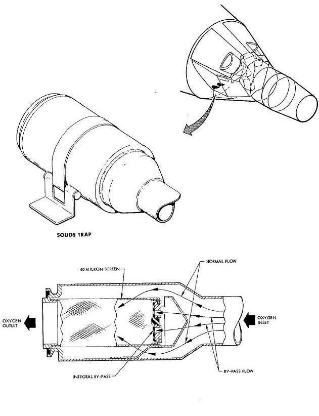
Solid traps, located in the oxygen outlet ducts of both pilots' suits, remove particulate solids, preventing contamination of the suit circuit system. An integral by-pass opens if the traps become choked with collected solids permitting continuous oxygen flow through the suit circuit.
Normal cabin leakage allows the cabin pressure to decay to a nominal value of 5.1 psia. The cabin pressure control valve maintains this value automatically.
A dual cabin pressure regulator supplies makeup oxygen through the pilots' pressure suits to the cabin on demand, as sensed by two aneroid elements within the regulator. The regulator supplies the makeup oxygen at a controlled pressure between 5.0 to 5.3 psia.
One or bothof the pilots may open their faceplates. The cabin air circulating valve is in the open position to provide for recirculation of the cabin oxygen through the suit circuit.
In the event of spacecraft depressurization, whether intentionally or by space-craft puncture, the dual cabin pressure regulator closes when cabin pressure decreases to 4.1 +.2/-.1 psia, preventing excessive loss of oxygen.
The suit circuit demand regulator senses cabin pressure and maintains suit circuit pressure at 2.5 to 3.5 inches of water below to 2 to 9 inches of water above cabin pressure. Should cabin pressure decrease below 3.5 psia, the suit circuit demand regulators maintain the suit circuit pressure at 3.5 +0.4/-0.0 psia by constant bleed orifices and sensing aneroids within the regulator. When cabin pressure is restored to 5.1 +0.2/-0.1 psia, the suit circuit demand regulators return to normal operation.
In the event of cabin and suit circuit malfunction, the suit circuit will automatically revert to the high rate of operation when suit circuit pressure decreases below 3.0 -0.0 psla. A suit circuit pressure sensing switch energizes the solenoid of the dual high flow rate and system shutoff valve. This initiates a high oxygen flow rate of 0.08 +/- 0.008 lbs per man (total flow:0.16 lb/min). This high flow rate flows directly into the suits by-passing the suit demand regulators. The suit recirculating system is shut off and the suit compressors are de-activated when the solenoid of the dual high flow rate and system shutoff valve has been energized. The 02 HI RATE light on the center panel illuminates when the suit circuit is on the high flow rate. There is also a manual control for the high flow rate and system shutoff valve located on the center console.
When the suit circuit pressure is restored to a level above 3.0 + 0.1/- 0.0 psia, the high rate and system shutoff valve is reset manually by using the control marked 02 HIGH RATE RECOCK located on the center panel. This returns the suit circuit to normal operation by opening the system shutoff valve and closing the high rate valve. The suit compressor is also reactivated.
The drinking water system is pressurized and manually controlled by the pilots. Water from the adapter supply is used to replenish the cabin tank water supply.
The water tank drink selector valve is set in the NORM position. The pilots manually operate the drinking dispenser to provide drinking water from the cabin storage tank.
The water separator removes metabolic moisture through a wicking
material
positioned between the plates of the suit heat exchanger.
The Chemical Urine Volume Measuring System (CUVMS) has a four
position selector valve labeled URINATE, SAMPLE, DUMP, and BY-PASS.
Position selection is made by rotating the selector valve which is
attached to a multi-ported center plug. The selector valve includes a
positive displacement tracer metering pump which is activated by the
handle as it passes over a plunger between the BY-PASS and URINATE
positions. This supplies a quantity of tracer solution to the passages
to mix with the urine in the collection/missing bag. Therefore, volume
measurement can only be accomplished when the selector is in the URINATE
position and the tracer
chemical is added. The urine receiver assembly and collection bag
provides for collecting and sampling urine or overboard dump provisions
but does not provide for volume measurement. The urine quick-disconnect
hose and filter assembly consists of a section of flexible hose with
quick disconnect couplers on each end. This assembly connects the CUVMS
or the urine receiver assembly to the water management panel through an
in-line urine solids trap filter for dumping urine overboard. The urine
sampling bags are plastic laminate with a valve that connects to the
sampler port on the CUVMS or the urine receiver assembly for taking
urine samples. The urine receiver roll-on cuff is the interface between
the crewmen and the CUVMS or the urine receiver assembly. It provides an
air and liquid tight seal for direct urine transfer. Selector valve
positions on the CUVMS direct urine flow as follows. The SAMPLE position
directs urine and tracer chemical mixture from collection/mixing bag to
the sample port and into the sampling bag. The DUMP position directs the
urine/tracer chemical mixture overboard.
The BY-PASS position (normal purge position) directs the urine flow to
the water management panel for dumping overboard.
The dump selector valve on the water management panel is positioned to route the urine either to the water boiler or dumped overboard. The normal procedure is to dmnp. Before it is dumped the urine dump system is preheated by positioning its heater switch located on the water management panel. A urine dump heater light is also provided and located on the water management panel. This light illumluates when the heater is activated.
The primary oxygen system is disconnected when the adapter section is separated from the re-entry module. This removes the primly oxygen supply pressure which automatically activates the secondary oxygen supply.
The system shutoff and high rate valve is positioned to the high rate position before the adapter section is Jettisoned.
The pressure in the suit and cabin remains constant at 5 psia (nominal) until an altitude of approximately 27,000 feet is reached.
As ambient pressure increases during descent, the cabin pressure relief valve admits ambient air into the cabin, preventing high differential pressures. The cabin pressure relief valve begins to open when the ambient pressure is 15.0 inches of water greater than cabin pressure and opens to maximum flow when the pressure differential is 20 inches of water.
At an altitude of 25,600 feet, or below, the pilots manually open the cabin inflow and outflow valves to circulate external air through the cabin and suit circuit.
Maximum negative pressure on the cabin should not exceed 2 psi as controlled by the cabin relief valve.
Prior to re-entry the face plates should be closed. The hlgh flow rate of oxygen is flowing directly into the suit circuit.
When the cabin inflow valve is opened It activates the suit compressor and external air Is circulated through the suit circuit.
Ventilation is provided by the suit compressor as long as electrical power is available (12 hours minimum).
Ambient air is drawn into the vehicle through the snorkel inflow
valve, by the
suit compressor, circulated through the suit circuit into the cabin,
then
discharged overboard through the outflow vent valve.
The snorkel inlet valve functions as a water check valve. When the
snorkel inlet valve is above water level, the ball check is retained
freely in a wire mesh cage permitting ambient air to enter the suit
circuit. Normal oscillations
of the spacecraft in the sea may result in the snorkel valve being
momentarily submerged. This will cause the ball check to seat and is
held there by suction from the suit compressor. Opening the cabin air
circulating valve allows the ball to drop from its seat.
To prevent water from entering the cabin through the cabin pressure relief valve, the manual shutoff section of the valve is closed.
If cabin depressurization becomes necessary due to toxic contaminants or fire, the cabin outflow valve is opened to depressurize the cabin. The cabin regulator will close stopping the oxygen supply to the cabin, permitting the escape of toxic contaminants and preventing oxygen assistance to combustion in the event of fire. The cabin repressurization valve permits repressurization of the spacecraft cabin.
The control knob for the cabin repressurization valve is located on the lower console and is rotated counterclockwise to open the valve. It is rotated clockwise to close the valve when cabin pressure is between 4.3 and 5.3 psia. Cabin pressure is then automatically controlled at 5.1 +00.2/-0.1 psia by cabin pressure regulator valve.
DUAL SECONDARY OXYGEN RATE AND SUIT SYSTEM SHUTOFF VALVE
The dual secondary oxygen rate and suit system shutoff valve provides
a constant flow rate of oxygen directly to the pilot's suit during
re-entry or in the event the suit circuit malfunctions during launch or
orbit.
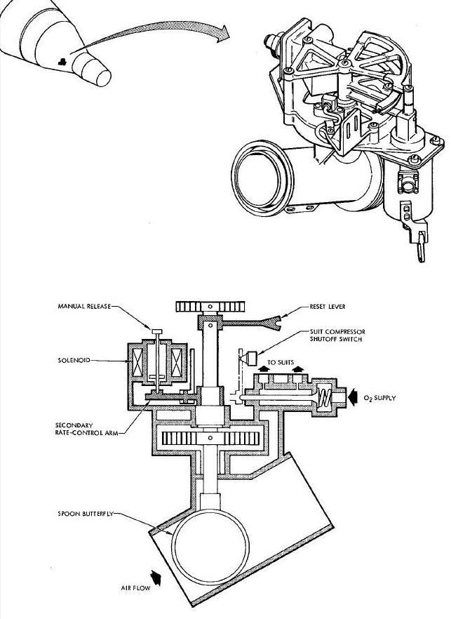
The valve is designed for manual and automatic initiation. The recirculating suit oxygen circuit flows through the shutoff section of the valve, which is manually opened and is spring loaded to the closed position. The shutoff valve is held open by a 24 vdc solenoid pin, as long as the solenoid is de-energized. The secondary flow poppet valve, held closed by spring tension, remains closed whenever the shutoff valve is in the open position. When the solenoid is energized, the butterfly arm is released and rotates by spring tension, closing the suit circuit valve and mechanically opening the secondary oxygen flow rate poppet valves. Opening the poppet valves allows oxygen to flow to each pilot's suit through fixed orifices at a rate of 0.08 + 0.008 Ib/min per man (total flow 0.16 Ib/min.). The butterfly arm simultaneously actuates a switch that de-energizes the solenoid, turns off the suit compressor and cabin fan, and illuminates a SECONDARY FLOW RATE lamp on the pilots' center display panel. A pressure sensor switch attached to each pilot's suit circuit will energize the solenoid if the suit circuit pressure in either suit decreases below 3.0 +O.1/-0.0 psia, atomically shutting off, the suit circuit flow and initiating the secondary flow rate. A manual control is provided for resetting the valve to the normal position. The secondary flow rate is used during re-entry. Prior to retro-grade the pilots manually disengage the solenoid initiating the secondary flow rate.
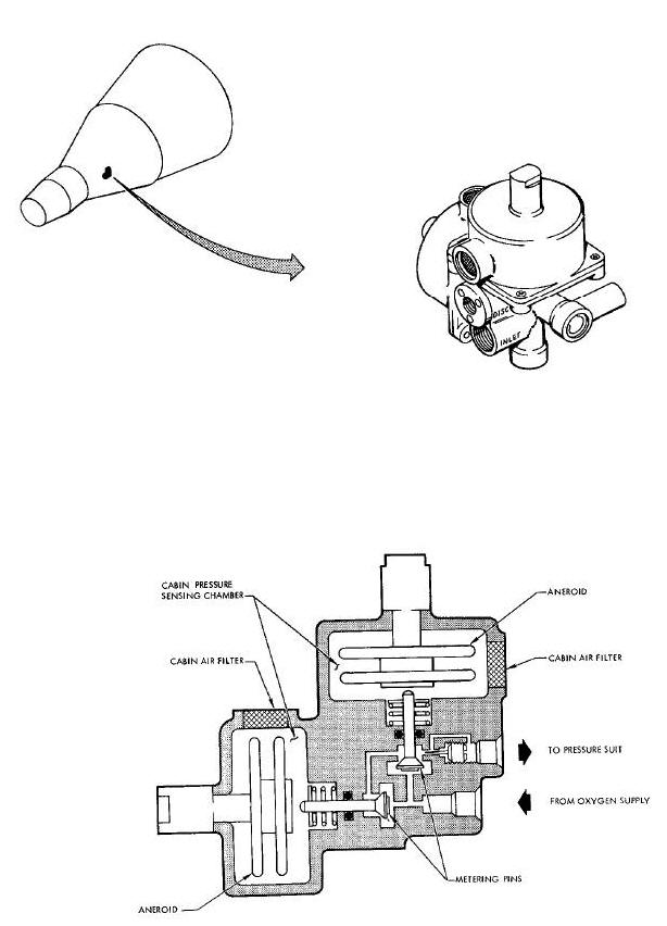
SUIT OXYGEN DEMAND REGULATOR
The suit oxygen demand regulator controls the oxygen to the suit circuit from the primary or secondary oxygen system and replenishes oxygen used by the pilots or lost by leakage.
Suit Oxygen Demand Regulator Diagram
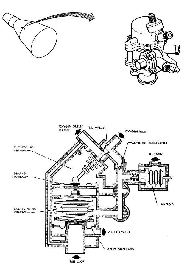
Cabin pressure is sensed on one side of the diaphragm and suit pressure
is
sensed on the opposite side of the diaphragm. The differential pressure
across this diaphragm opens or closes a poppet valve admitting or
stopping oxygen flow into the suit circuit. With cabin pressure of 5.0
psia the suit regulator maintains suit pressure at 2.5 to 3.5 inches of
water below cabin pressure.
A resilient diaphragm type valve relieves pressure in the suit during ascent and limits excess pressure to between 2.0 and 9.0 inches of water above cabin pressure. During descent, the suit demand regulator relieves the secondary oxygen rate flow through the relief portion of the valve, maintaining suit pressure 2 to 9 inches of water above cabin pressure.
A constant bleed and aneroid elements maintain the suit pressure at
3.5 +0..4/-0.0 psia if cabin pressure decreases below this pressure. The
bleed flow by-passes the tilt valve through a bleed orifice and is
directed to the cabin pressure sensing side of the pressure demaud
diaphragm. A metering valve, controlled by an aneroid, regulates the
reference pressure on the demand diaphragm. The regulator returns +0.2
to normal operation when cabin pressure returns to 5.1 -0.i psia. In the
event that cabin decompression and a ruptured relief diaphragm in the
regulator occur
simultaneously, an aneroid over the relief diaphragm extends to control
suit
pressure at 3.9 psia maximum.
The cabin pressure relief valve automatically controls the
cabin-to-ambient
differential pressure during launch, orbit and re-entry. Duplicate
spring
loaded poppet valves are controlled by servo elements within the valve.
The servo elements control spring loaded metering valves which determine
the pressure within the diaphragm chamber behind the poppet,
controlling the poppet position. A small inlet bleed orifice admits
cabin pressure to the diaphragm chamber. When the poppet opens, a large
orifice permits rapid change in pressure ensuring quick closure of the
poppet.
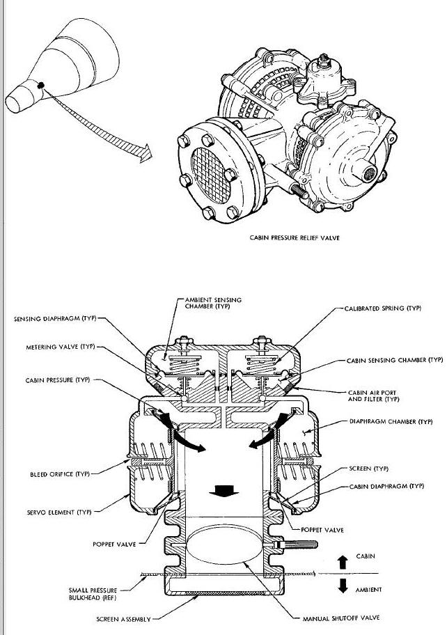
During ascent the valve will relieve cabin pressure as emblent
pressure decreases until cabin differential pressure is 5.5 to 6.0 psia.
The valve closes maintaining differential pressure in this range. When
cabin pressure decresses below 5.5 psia the servo element closes the
metering valve meintaining reference pressure within the diaphragm
chamber at cabin pressure. The poppet is held closed by spring force and
the zero differential between the diaphragm and the cabin prevents cabin
pressure release. If cabin differential pressure exceeds 5.5 psia the
zero element retracts, opening the metering valves, allowing the
diaphragm chamber to discharge to ambient. The discharge port being
larger than the inlet bleed orifice permits the diaphragm chamber to
approach external pressure. The cabin pressure reacting on the diaphragm
overrides the poppet spring force, which opens permitting cabin pressure
relief to ambient. During descent, as external pressure increases,
ambient air is admitted to the cabin by the valve to reduce the
differential
pressure. As external pressure increases above the cabin pressure the
metering valves are held on their seats, preventing external pressure
from entering the diaphragm chamber and retaining cabin pressure in the
chamber. The poppet valve senses diaphragm chamber pressure versus
ambient pressure. When the ambient pressure is 15 inches of water
greater than cabin pressure the poppet begins to open permitting ambient
air to enter the cabin. The poppet opens fully when the differential
pressure is 20 inches of water.
To preclude water entering the cabin during postlandlng, a manual
shutoff valve is provided.
Two electric motor driven, single stage compressors are incorporated in the suit circuit. One compressor is utilized for circulation of the gases within the suit circuit, supplying both suits. The other compressor functions as a backup and is activated only by manual selection by the pilots. Either compressor can be manually selected by a switch on the center display panel, and both compressors can be selected simultaneously.
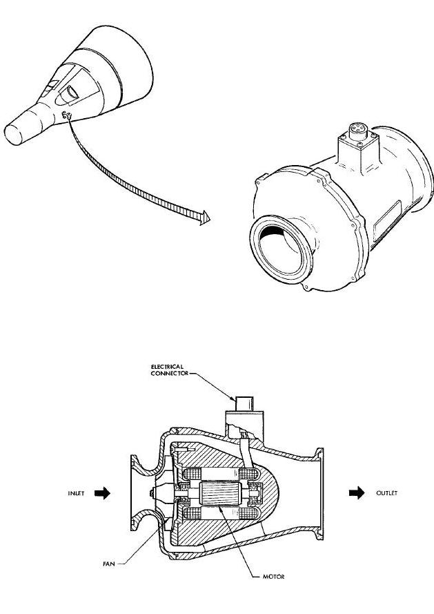
When secondary oxygen flow rate is selected, the compressor is
automatically deenergized. Re-entry is made using the secondary rate. At
an altitude of 25,600 feet or below the manual inflow valve is opened
which re-energizes the compressor. The suit compressor provides
ventilation during landing and for a twelve hour postlanding period, or
until the batteries fail.
A solids trap is located in the oxygen outlet duct of each suit. A cylindrical 40 micron filter strains the gaseous flow in the suit circuit removing the solid matter. In the event that the trap becomes choked with collected solids, an integral by-pass opens when the differential pressure across the screen exceeds 0.50 inches of water.
The cabin pressure regulator maintains cabin pressurization by providing makeup oxygen to the cabin on demand. The regulator contains two aneroid elements which individually sense cabin pressure. When cabin pressure decreases, the aneroid expand, forcing metering pins open and permitting oxygen flow into the cabin, maintaining cabin pressure at 5.1 +0.2/-0.1 psia. If the cabin is punctured or develops leakage greater than the flow capacity of the valve (4.79 + 0.48) 10-3 ib/mln, oxygen flow to the cabin is stopped when the cabin pressure decreases to 4.0 +0./-0.1 psia, by the aneroids expanding enough to cause the metering to close off the oxygen.
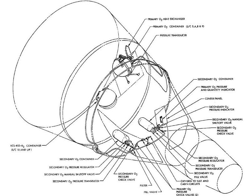
PRIMARY SUPERCRITICAL OXYGEN CONTAINER
The primary oxygen container is a double walled tank. A dual concentric cylinder, quantity measuring devices I heaters and heat transfer spheres are internal to the container. The tank contains two heaters. The first is a 12.0 +/- 2 watt heater which is activated either manually by a switch located on the center panel 3 or automatically by a pressure switch. The pressure switch controls the activation of the heating element in the tank to automatically maintain the cryogen in a supercritical state. The switch de-energizes the heater circuit when the pressure in the tank is between 875 to 910 pslg, and closes the circuit 15 to 75 psig below the opening pressure. The second heater is a 325 -0 watt heater manually controlled by a switch located on the overhead switch/circuit breaker panel.
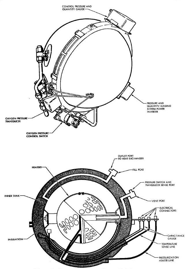
The pressure relief valve maintains the oxygen pressure within the container at 1000 +0/-55 psig, and prevents overpressurization of the containers. Provisions for servicing the primary oxygen container from a ground supply source of oxygen are provided.
The secondary oxygen container is a cylindrical shaped container, having a useful oxygen capacity of 6.5 pounds at an operating pressure of 5000 psig.
C
CUVMS - Chemical Urine Volume Measuring System
E
ECS - Environmental Control System
F
FC - Fuel Cell
R
RSS - Reactant Supply System
S
scc/min - standard cubic centimeters per minute, (scc/min)