 |
 |
AUGMENTED TARGET DOCKING ADAPTER (Agena)
Augmented Target Docking Adapter Diagram
REACTION CONTROL SYSTEM MODULE
ATDA/LAUNCH VEHICLE SEPARATION
POWER AND SEQUENTIAL RELAY PANEL
Electrical Power System Installation Diagram
Electrical Power System Schematic Diagram
POWER AND SEQUENTIAL RELAY PANEL
Communication System Block Diagram
C-Band Radar Transponder Block Diagram
Digital Command System Block Diagram
Telemetry Transmitter Block Diagram
UHF Ascent, Stub, and Whip Antennas Diagram
C-Band Antennas and Power Dividers
C-Band Antennas, Diplexers, And Coaxial Switches Diagram
C-Band Beacon and Telemetry Transmitters Diagram
DCS Receiver/Decoder and Relay Boxes Diagram
Instrumentation System Diagram
Instrumentation System Block Diagram
TARGET STABILIZATION SYSTEM PARAMETERS
DIGITAL COMMAND SYSTEM PARAMETERS
REACTION CONTROL SYSTEM PARAMETERS
RENDEZVOUS RADAR TRANSPONDER PARAMETERS
INSTRUMENTATION SYSTEM PARAMETERS
Signal Conditioner & Temperature Sensor Diagram
DC-DC Converter and PCM Programmer Diagram
Pyrotechnic Devices and Separation Assemblies Diagram
Pyrotechnic Devices and Separation Assemblies
Pyrotechnic Devices and Separation Assemblies Diagram
Pyrotechnic Valves and Explosive Bolts Diagram
Mechanical Separation Assembly Diagram
Shroud Separation Assembly Diagram
ATDA/IAUNCH VEHICLE SEPARATION ASSEMBLY
Target Stabilization System Diagram
Positive and Negative Switches
ORBIT ATTITUDE AND MANEUVER ELECTRONICS
Reaction Control System Schematic
Reaction Control System Schematic
THRUST CHAMBER ASSEMBLY GROUP DIAGRAM
PROPELLANT SUPPLY SHUTOFF VALVES
PROPELLANT SUPPLY SHUTOFF VALVES
ATDA DESCRIPTION
The Augmented Target Docking Adapter (ATDA) is an alternate target vehicle for the Gemini Spacecraft. The ATDA may be substituted for the Agena Target Vehicle provided sufficient mission objectives can be accomplished. The ATDA is capable of performing all but one of the major functions of the Agena. The ATDA is not capable of a translational maneuver. It does, however, have small thrusters to control attitude rates.
The ATDA (Figure Below) consists of a Target Docking Adapter (TDA) augmented with power, communication, instrumentation and stabilization systems. It is made up of five major sections or modules. They are: the ascent shroud, the TDA, the equipment section, the Reaction Control System (RCS) module, and the battery module. Only the equipment section, part of the TDA, and the ascent shroud are visible when the ATDA is mated with the launch vehicle. A mating ring attached to the equipment section, mates the ATDA to the launch vehicle.
Augmented Target Docking Adapter Diagram
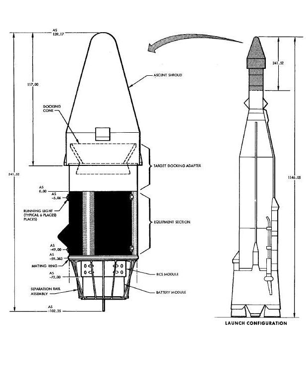
The ATDA is cylindrical in shape; approximately
11 feet long, 5 feet in diameter at the greatest cross section and 3
feet at the smallest. Although constructed for the most part of aluminum
alloy, the ATDA weighs a Little over 2000 pounds with all equipment
aboard. To aid in locating the ATDA during daylight hours, the equipment
section is painted black with white longitudinal stripes. The
other sections and modules are aluminum color.
The ascent shroud is a weather tight Jettisonable fairing, constructed of phenolic fiberglass. It is 9 feet 9 inches high and 5 feet 5 inches in diameter. The shroud is used to protect the TDA from aerodynamic pressures and thermal damage during launch. At the end of the boost phase, the shroud is Jettisoned by a ground command to expose the docking cone for mission operation.
The TDA is an electrmmechanical unit constructed to receive the Gemini Spacecraft and to rigidly dock with it. The TDA is 5 feet in diameter and approximately 4 feet long. The TDA consists of two major assemblies; a docking cone and an adapter. The docking cone has a V-shaped notch to provide a roll alignment path for the spacecraft during the docking maneuver. The adapter assembly mates the TDA to the equipment section and is the mounting structure for all TDA components. A complete description of the TDA is contained in Section XIV of this manual.
The equipment section is 60 inches in diameter and 54 inches long. This section contains the largest concentration of the ATDA electronic components. The components are mounted on internal cross beams. Entry into the equipment section is provided by four access doors.
REACTION CONTROL SYSTEM MODULE
The RCS module is approximately 40 inches in diameter and 18 inches long. The module contains two side-by-side rings of eight thrust chamber assemblies and duplicate fuel, oxidizer, and pressurant supplies. The RCS supply tanks are mounted on the RCS module but extend into the equipment section.
The battery module contains the three main batteriem and two squib batteries. The module is 36 inches in diameter and approximately 18 inches long.
Before the ascent shroud is installed on the ATDA, the docking cone is rigidized. During pre-launch operations, ground personnel check out the ATDA using on-board equipment in conjunction with Aerospace Ground Equipment (AGE). AGE power cables are used to supply power to the ATDA systems during pre-launch to prevent depletion of the batteries. The cables are removed and internal power selected Just prior to lift-off.
The ATDA is boosted by an Atlas Launch Vehicle into a circular orbit. (See Figure Below). At the end of the boost phase, the ATDA is separated from the launch vehicle; the ascent shroud that covers the TDA is Jettisoned; and all systems that are used in orbit are turned on or put in readiness to operate.
As the ATDA passes over the launch facility, a Gemini Spacecraft is launched into an elliptical coplanar orbit. A catch-up maneuver is performed by the spacecraft. When the spacecraft gets within radar range (appromately 250 miles), rendezvous computations are performed and the spacecraft is maneuvered within 100 feet of the ATDA. At this time relative velocities and attitudes are adjusted in preparation for docking.
While the docking maneuver is being performed, ATDA systems stabilize the rotation of the ATDA in all three axes. When the spacecraft enters the docking cone, the docking latches engage and the rigidize motors are actuated. The spacecraft is docked and rigidly connected to the ATDA. Commands to unrigidize and unlatch can be given via the hardline umbilical which mates during the docking sequence or by ground commands
Eight systems establish the rendezvous and docking capability of the ATDA. These systems are: Docking, Sequential, Electrical Power, Communication, Instrumentation, Target Stabilization, Reaction Control and Lighting. Sequential functions, such as ATDA/launch vehicle separation, ascent shroud separation, and RCS activation, are performed by pyrotechnic devices and mechanical separation assemblies. These are described in a separate subsection.
The Docking System is utilized to mate, secure, and rigidize the spacecraft with the ATDA. A detailed description of the Docking System is contained in Section XIII.
The Sequential System prepares the orbiting ATDA for rendezvous and docking with the Gemini Spacecraft. The system controls the sequence and timing of events which occur at ATDA/launch vehicle separation.
The Electrical Power System consists of the batteries and buses which supply and distribute dc power to all the systems of the ATDA. The system includes a means of substituting ground power for the on-board batteries in order to checkout the ATDA systems before launch.
The Communication System provides the means of tracking the ATDA transmitting information as to the condition and progress of the ATDA. The Communication System also accepts switching commands from the ground station.
The Instrumentation System monitors and collects information on the environmental conditions of the ATDA and on the operational conditions of its electronic and electromechanical equipment. This information is assembled in the proper format and signal conditioned (if necessary) by the Instrumentation System, for transmission to the ground station by telemetry.
The Target Stabilization System (TBS) monitors the attitude rates of the ATDA and generates thrusting commands to control it at preselected rates.
The RCS is the dual rings of eight small thrusters each. These thrusters are fired by TSS commands. They produce the yaw, pitch, and roll thrust to control the ATDA at the selected attitude rate.
The Lighting System consists of the acquisition, approach and status display panel lights on the TDA, and the running lights on the equipment section. A description of the TDA lights is contained in Sections XIII and XlV
The six running lights are mounted on the
surface of the ATDA equipment section. Two are green, two red, and two
amber. Viewing the space vehicle from the TDA end, the green lights are
on the top left, the red on the top right, and the amber at the bottom.
Lights of the same color are arranged on a longitudinal line with each
other. The unfiltered intensity of each lamp is approximately
21 candlepower. The dome-shaped color filters which cover each lamp
reduce the light transmission less than 15 percent. Each lamp and color
filter is covered with a clear protective dome.
The operational readiness of the running lights
is checked during pre-launch. At lift-off, all lights on the ATDA are
off. They remain off during the boost phase. At the end of the
separation events, all TDA lights and the running lights are turned on
together. The lights may be left on until the Gemini Spacecraft and ATDA
rendezvous. If the rendezvous exercise is not carried out as scheduled
or if there is some reason for conserving electrical power, all ATDA
lights can be turned off by a ground command. Ground station digital
command can turn these lights on again. After docking, the acquisition
lamps can be turned off by hardline umbilical commands.
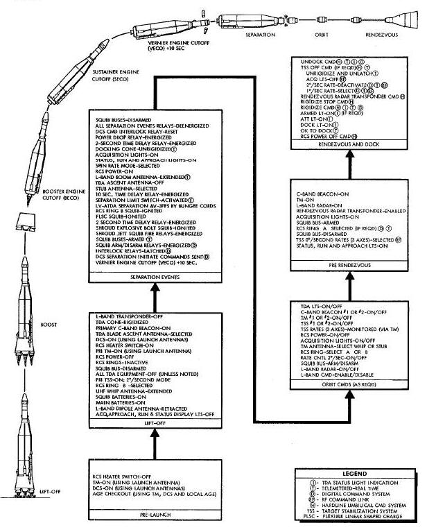
fhe Sequential System (Figure
Below) consists of twenty-three
relays, two relay panels and three sensors which control or monitor
events occurring at separation. These events occur shortly after Vernier
Engine cut-off (VECO) and prepare the ATDA
for rendezvous and clocking with the Gemini Spacecraft. There are 10
sequential events which occur at this time. They are; jettison the
ascent should; separate the ATDA from the launch vehicle; activate ring
B of the Reaction Control System (RCS); turn on the acquisition,
approach, running and status display lights; extend the L-band Dipole
antenna; unrigidize the docking cone; select the uhf
stub antenna remove squib bus power from the squib fire relays and spent
squibs reset the latch relays; and disarm the squib buses, fire
Sequential System also monitors some of these events for the purpose of
telemetry confirmation to ground stations.
Ten seconds after VECO, Sequential System operation is initiated by the Digital Commend System (DCS). This starts a chain of events which continue in an unbroken sequence for approximately 12 seconds. After the last sequential event has been performed, power !s automatically removed from the Segmental System relays.
The Sequential System obtains most of its power from squib buses 1 and 2. These buses are armed simultaneously with the initiation of the separation sequence. Prior to VECO, DCS command to preselect squib bus arming (channel 1), and separation command initiate (channels 9 and 21) are sent. These commands connect the latch coils of the squib bus arm relays and the separation command initiate relays to the DCS pulse bus. An open set of contacts on both separation command initiate relays is also ready to connect the latch coils of the squib bus arm relays to the common control bus.
When the primary DCS execute on command (channel
18) is sent at VECO plus 10 seconds, the DCS pulse bus is armed. The DCS
pulse bus ant the separate command initiate relays redundantly latch the
squib bus arm relays. (See
Figure Below)
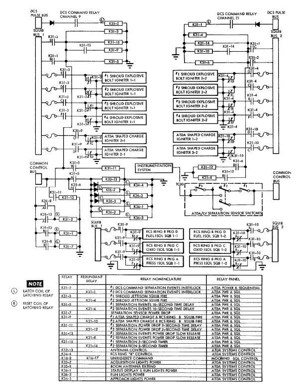
The primary DCS execute on command latches the 1 and 2 DCS command separation interlock relays, K31-2 and K31-1. K31-2 and K31-1 interlock the Sequential System in the on condition until a cycle of operation has been completed. K31-2 and K31-1 energize shroud Jettison relays K31-3 and K31-4, separation 2-second timer relays K31-15 and K31-14, and separation events 10-second time delay relays K31-5 and K31-6. The ATDA separation events begin to happen with the energizing of the shroud jettison relays.
The shroud jettison squib fire relays, K31-3 and
K31-4, energize immediately. Their C, D, E and F contacts connect squib
bus power to redundant igniters of four shroud explosive bolts.
Explosive charges cause the bolts to break as if sheared off. This
allows the shroud separation assembly, which is described in the
Pyrotechnics and Separation Assemblies subsection, to function. The
shroud
separates and falls away from the target vehicle.
Three time delays are built into the ATDA Sequential System. The time delays prevent the violence or rapid occurrence of one event from disrupting any other event. The first time delay is inserted between ascent shroud Jettison and mating ring separation. This delay is controlled by the separation 2-second timer relays, K31-14 and K31-15.
ATDA/LAUNCH VEHICLE SEPARATION
Two seconds after ascent shroud Jettison, K31-9 and K31-10 are energized. These are the ATDA shaped charge and the RCS ring B squib fire relays. Their C and D contacts connect the squib buses to the shaped charge igniters (or squibs). The shaped charges explode, severing the mating ring. The mechanical separation device now performs like a catapult. The bungee cords contract and shove the ATDA out of the launch vehicle with a separation velocity of 3 feet per second.
As the ATDA starts its movement away from the Atlas Launch Vehicle, the blast shield surface that held the plungers of the separation sensors in the preloaded position is left behind. The compressed springs in the sensors thrust the plungers downward and the linkages pull the toggles down to the closed positions. Only two of the three sensor switches need close to complete the sensing circuit. The closed switches connect common control bus power to the Instrumentation System Programmer. This bi-level signal is telemetered to the ground monitoring station as the ATDA separation parameter.
At lift-off, the RCS fuel and oxidizer tanks are isolated from the thrusters, and the nitrogen pressurant is isolated from the fuel and oxidizer tanks by pyrotechnic valves. The B, E and F contacts of relays K31-9 and K31-10 connect squib bus power to six RCS ring B pyrotechnic valves. The pyrotechnic valves fire, activating ring B of the RCS.
The second time delay begins when the execute command to initiate separation is given. It is timed redundantly by the separation events 10-second time delay relays, K31-5 and K31-6. When these relays energize, they connect the common control bus to the separation events relays. The separation events relays apply RCS power, select the uhf antennas, extend the L-band boom antenna, turn on the ATDA lights, and unrigidize the docking cone. The B contacts of K31-5 and K31-6 control the last 2-second time delay.
The RCS latching control relay, K34-4, connects common control bus power to all RCS solenoid valves. RCS ring A/ring B select relays were set at lift-off, by DCS command, to select ring B. The Target Stabilization System has been operating since lift-off, generating rate stabilization commands. These commands now switch the various RCS ring B thrusters on and off to stabilize the ATDA.
The antenna control relay, K32-13, connects the common control bus to the position 1 input on coax switch 3. This switches the primary telemetry transmitter and one of the DCS receivers from the uhf ascent blade antenna to the uhf stub antenna.
The L-band transponder antenna extend relsy,
K35-3, connects the common control bus to the extend terminals of the
antenna drive motor. Within 30 seconds, the transponder antenna rises to
e height of approximately 85 inches and closes the extend limit
switches. One of the switches removes the extension voltage from the
drive motor. The other switch connects the common control bus to the
Instrumentation System programmer. This parameter is telemetered to the
ground monitoring station, confirming that the L-band transponder
antenna has been fully extended.
The unrigidize command relays, K16-2 and K16-17, are latched, energizing the unrigidize winding of the mooring drive motor and the unlatch winding of the latch release motor. The mooring drive motor runs, activating three sets of unrigidized limit switches (one open and two closed). The latch release motor runs, closing the latch actuator limit switch. The opened set of limit switches causes power to be removed from the drive motor unrigidize winding. One closed set of limit switches resets the undock circuit. The latch actuator limit switch and the other set of closed limit switches completes a circuit between contacts of K36-I and the DOCK light on the status display panel. This circuit also causes the unrigidize parameter to be applied, through contacts of K16-20, to the Instrumentation System programmer. This parameter is telemetered to the ground station for telemetry confirmation of cone position. One set of rigidized limit switches opens to prevent the RIGID light on the status display panel from illuminating.
The acquisition lights are located on the top left and bottom right of the docking cone. The acquisition lights, like the docking cone behind which they are mounted, are held in a rigid retracted position during ascent. When the mooring drive motor unrigidizes the docking cone, the movement causes the lights to move outward from behind the cone into their operating positions. The acquisition lights power relay, K35-2, applies common control bus power to the lights.
The running lights power relay, K36-2, and status display and running lights power relay, K36-I,are latched. K36-2 connects main bus power to the red, green and amber running lights at station -5.00 which is near the Target Docking Adapter. K36-I applies the same power to the three running lights at station -49.00 near the RCS module. The running lights can be turned off by DCS command.
The status display panel on the ATDA is the same panel as the one used on the Agena Target Vehicle. However, the ATDA uses only four of the status display lights: DOCK, RIGID, ARMED and ATT (attitude).
The status display and running lights power relay, K36-1, which powered up three of the running lights, also connects power to the circuits which control the status display lights. At this time, only the DOCK light illuminates. The DOCK light illuminates green to indicate that the TDA cone is unrigidized and the docking latches are ready to receive an entering spacecraft. The green RIGID light which indicates a rigidized docking cone, the amber ARMED light which indicates RCS ring A has been activated, and the green ATT light which indicates that zero degree per second rates has been selected cannot illuminate now. These indicators will illuminate when the appropriate function has been selected by DCS command.
The approach light power relay, K36-3, connects main bus power to the two series-wired floodlights inside the TDA. These floodlights, called approach lights, are located near the bottom of the TDA and illuminate the space behind the docking cone for a visual approach. The two lights are turned on and off by the commands which control the running lights.
The third time delay is a 2-second interval between the start of the separation events and the removal of Sequential System relay power. This delay is provided by the separation power drop time delay relays, E31-11 and K31-12. The B contacts of K31-11 and K31-12 connect squib bus power, switched by K31-1 and K31-2, to the power drop slow release relays.
Many relays, energized by the ten second time
delay relays, are latching relays. Such relays are latched by permanent
magnets in the positions to which they have been switched. Hence, they
no longer need electrical power to maintain their selected positions.
Relays K32-13, K34-4, K35-I, K35-2, K35-3, K36-I, K36-2 and K36-3 are of
this kind. Power which was applied to their coils can be removed
without changing their contact positions.
Besides the latching relays, there are twelve relays, the contacts of which change when the relays are deenergized. These relays are used to fire the squibs and to produce time delays. After their functions are completed, power to their coils also may be removed.
The power drop sequence is accomplished in seven
steps: First, a 2-second time delay is placed between the application of
the separation events signal and the start of the power drop sequence.
The delay permits the separation events relays to reach a steady state.
Second, power drop 2-second time delay relays K31-11 and K31-12 close,
connecting squib bus power to power drop slow release relays K31-13 and
K31-8. Third, the power drop relays connect the common control bus to
the reset coils of K31-1 and K31-2. Fourth, K31-1 and K31-2 reset,
opening the circuit from the squib buses to K31-3, K31-4, K31-5, K31-6,
E31-9, K31-10, K31-14 and K31-15. Fifth, K31-5 8nd KS1-6 deenergize,
disconnecting squib bus power from eight separation events latching
relays and from K31-11 and K31-12. Sixth, K31-11 and KSl-12 deenergize,
disconnecting squib bus power from K31-15 and f- K31-8, the slow release
relays. Seventh, in approximately 40 to 70 milliseconds, K31-13 and
K31-8 deenergize, disconnecting the common control bus from the
reset coils of KBl-1 and KSI-2. This step completes the power drop-out
sequence.
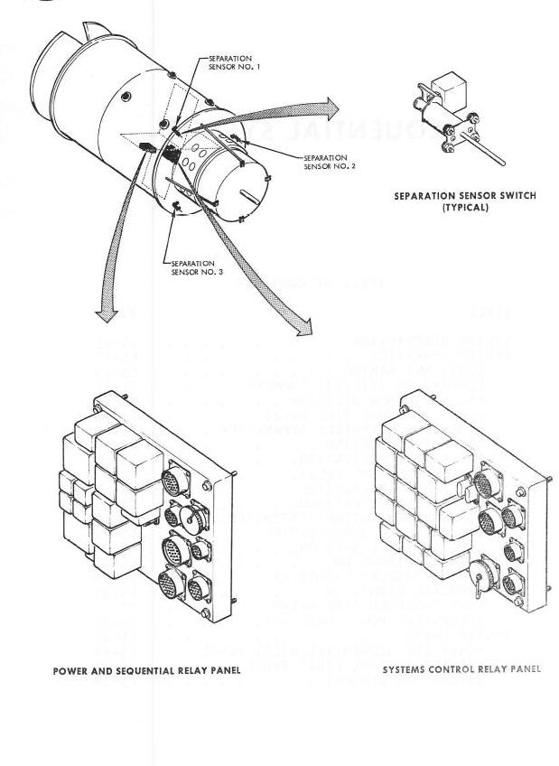
The units of the Sequential System are the relays, the relay panels and sensor switches which control or monitor the separation events. All of the Sequential System relays are located on the power and sequential relay panel and the systems control panel.
Although some unrigidizing relays are operated by the separation events signal, the relays and their relay panels are properly part of the Docking System. The sensor switches which monitor separation are discussed here, the pyrotechnic devices which cause separation and some of the separation events are discussed in the Pyrotechnics and Separation Assemblies subsection.
POWER AND SEQUENTIAL RELAY PANEL
The power and sequential relay panel is approximately 8.7 inches high by 9.8 inches wide by 3.5 inches thick. This panel is located in the equipment section of the ATDA and provides a mounting structure for fifteen sequential relays. These relays and their functions are identified in the Figure Above . Seven connectors provide electrical access to the relay solenoids and contacts. Relays mounted on this panel are identified by a K31 series reference designation.
The systems control relay panel is approximately 7.5 inches high by 11.5 inches wide by 3.5 inches thick. This panel is located in the equipment section of the ATDA and provides a mounting structure for eight sequential relays. Seven of these relays and their functions are identified in the Figure Above. The remaining relay, K35-1 is used to complete a telemetry path, confirming when the docking cone is unrigidized. In addition to the sequential relays, eleven system control relays are located on this panel. These relays are used to select secondary systems or different modes for the various ATDA systems. Six connectors provide electrical access to relay solenoids and contacts. Relays mounted on this panel are identified by a KS2 through K36 series reference designation.
The separation sensors are electromechanical devices used to detect the separation of the ATDA from the launch vehicle. The electrical part of the sensor is a double-pole double-throw toggle switch. 0nly switch 2 uses both poles. (See Figure Above.)
The mechanical part of the sensor is a bracket, on which the switch is mounted, and a linkage designed to operate the toggle. The linkage is basically a plunger or piston confined in a housing. Shafts attached to both faces of the plunger extend out the top and bottom of the housing. The bottom shaft, which is narrow, controls the position of the plunger. The top shaft, which is thicker, has an oblong hole, somewhat larger than a toggle switch handle, machined into it. A compression spring fits over the top shaft inside the housing and holds the plunger against the bottom of the housing. The toggle of the switch extends into the top shaft hole which pulls the toggle into the down or closed position.
Three separation sensors are mounted in the end
of the equipment adapter where it interfaces with the launch vehicle
mating ring. Each sensor fits through a hole cut in the end of the
equipment section, so that the control shaft extends into the mating
ring. A heat and shrapnel protective shield surrounds the inside of the
mating ring and forms a trough. The sensor shafts rest against the
bottom
of this trough. When the vehicles are mated, the trough pushes the
shafts and plungers upward in the housing, compressing the springs and
moving the toggles to the up position. These are the launch positions of
the separation sensors. When the shaped charge severs the mating ring,
the trough stays with the launch vehicle and the sensors leave with the
ATDA. The spring loaded sensor switches now complete the path from the
common control bus to the Instrumentation System.
The Electrical Power System for the Augmented Target Docking Adapter (ATDA) basically consists of three silver-zinc main batteries, two silver-zinc squib batteries, a control and monitoring panel, a diode panel and relays for controlling squib bus power. Refer to Figures Below 15-5 and the other Figure Below 15-6.
Electrical Power System Installation Diagram

Electrical Power System Schematic Diagram
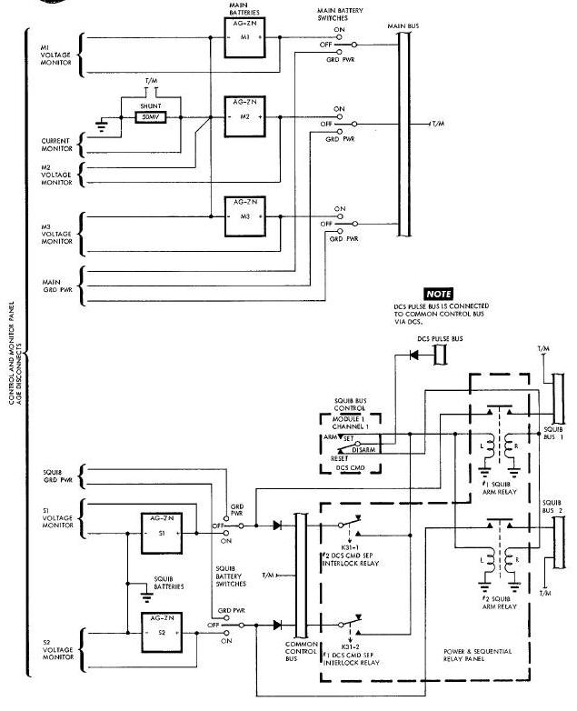
The three main batteries provide dc power to the ATDA main power bus. The two squib batteries provide dc power to the common control bus and the two squib power buses which are isolated from the main and common control bus. The control and monitoring panel provides switching for the power system and the capability for utilizing Aerospace Ground Equipment (AGE) external dc power and remote monitoring of the power system parameters.
The diode panel provides electrical isolation between the two squib batteries for individual battery fault protection. All of the power system circuits are of a redundant nature. No primary ac electrical power system is provided for the ATDA. Devices requiring ac power will obtain this power from self-contained inverters within the individual systems.
Both squib batteries supply power to the common control bus. Squib battery 1 and squib battery 2 are separately connected to squib bus 1 and 2 respectively via the squib bus arm relays. These relays are controlled by the Digital Command System (DCS).
The three main batteries and two squib batteries are installed in the battery module, which is located in the opposite end of the ATDA from the docking adapter. The control and monitoring panel, diode panel and power and sequential relay panel (containing the squib bus arm relays) are located in the equipment section of the ATDA.
In order to conserve the ATDA batteries, AGE external dc electrical power is utilized during pre-launch checkout of the ATDA systems. External power is supplied to the ATDA through AGE cables connected to the control and monitoring panel receptacles. Remote monitoring of main bus current, individual main battery voltage and individual squib battery voltage is also accomplished through the AGE cables.
External power is applied to the main power bus and common control bus by setting the MAIN BATTERY and SQUIB BATTERY switches to the GRD PWR position. Just prior to launch, all battery switches are set to ON position and the AGE cables are removed from the ATDA. The squib power buses are not armed prior to launch.
The squib power buses are armed via the two squib arm relays just prior to orbital insertion. The relays are energized to latch position by a command from the DCS. Comnon control bus voltage, squib bus 1 and 2 voltage and maln bus voltage and current are monitored by the Instrumentation System.
After the required squib functions for orbital insertion are accomplished, the squib buses are disarmed by a command from the DCS and may be rearmed if required. The squib buses are disarmed prior to rendezvous of the spacecraft with the ATDA.
The three ma!n batteries are 400 ampere/hour, 16 cell, silver-zinc batteries and are identical to the adapter power supply batteries used on spacecraft 6. The two squib batteries are 15 ampere/hour, 16 cell, silver-zinc batteries and are identical to the squib batteries used in the spacecraft.
The main battery cases are constructed of magnesium. The approximate activated (wet) weight of each main battery is 118 lbs. The squib battery cases are constructed of titanium. The approximate wet weight of each squib battery is 8 lbs. The squib batteries are special high-discharge-rate batteries which will maintain a terminal voltage of 18 volts for one second under a 75 Ampere load. All of the silver-zinc batteries have an open circuit terminal voltage of 28.8 to 29.9 volts.
The battery electrolyte consists of a 70 percent solution of reagent grade potassium hydroxide and distilled water. The squib batteries have a vent valve in each cell designed to prevent electrolyte loss. The valve will vent the cell to atmospheric pressure in the event that a pressure in excess of 40 psig builds up within the cell.
All of the silver-zinc batteries are equipped with relief valves which maintain a tolerable interior to exterior differential pressure in the battery cases. The batteries are capable of operating in any attitude in a weightless state. Prior to installation into the battery module, the batteries are activated and sealed at sea level pressure.
The control and monitoring panel contains the main and squib battery switches and the Reaction Control System (RCS) heater switch. This panel also provides receptacles for connecting AGE external power and test cables to the ATDA.
The diode panel contains diodes required to provide individual fault protection for the squib batteries. The squib batteries are connected to the common control bus via these blocking diodes to provide battery isolation.
POWER AND SEQUENTIAL RELAY PANEL
The power and sequential relay panel, which is essentially part of the Sequential System, contains the squib bus arm relays in addition to the other sequencing and control relays. The squib arm relays are controlled by the DCS and redundantly by the Sequential System.
The Communication System is the only communication link between the ground and the Augmented Target Docking Adapter (ATDA). The Communication System provides the following capabilities: radar tracking of the ATDA, ground command to the ATDA, and telemetry transmission. To make possible these various capabilities, the Communication System components may be divided into the following categories: antennas, including diplexers and coaxial switches; beacons; telemetry transmitters; and a Digital Command System (DCS).
The Communication System components are located throughout the ATDA with the largest concentration being in the equipment section. The location of the Communication System components is illustrated in Figure Below .
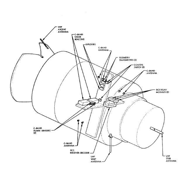
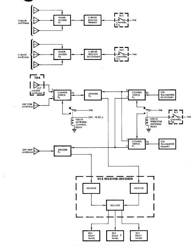
Three uhf antennas and two sets of C-band helical antennas provide transmission and/or reception capabilities for the various Communication System components. The Communication System (Figure Below) contains the following antennas: uhf stub, uhf whip, uhf ascent, and two sets of C-band helical antenna's. Each set of C-band antennas consist of a power divider and three helical antennas. Three coaxial switches permit antenna and transmitter/receiver switching for best DCS and telemetry communication with the ground stations during the various phases of the mission (pre-launch, launch, orbit, and docking).
Communication System Block Diagram
Two C-band radar beacons establish the capability of tracking the ATDA during the mission. The beacons are transponders which, when properly interrogated by the ground station, transmit signals for accurate ATDA tracking. The radar beacons are controlled by DCS commands from the ground stations.
Two identical transmitters supply the radio frequency link from the ATDA to the ground for transmission of instrumentation data. During pre-launch the telemetry transmitters are used for pad checkout of the ATDA. During orbit, telemetry transmission is made while the ATDA is in range of a ground station.
The DCS is the communication link for ground commands to the ATDA. The DCS receives and decodes command transmissions from the ground stations. These commands are used to operate relays which control the operation of various ATDA equipment.
The DCS consists of a receiver-decoder and three relay units located in the equipment section. The DCS operates from pre-launch throughout the mission.
The ATDA Communication System operates from pre-launch throughout the mission. The sequence and theory of operation of the Communication System is as described in the following paragraphs and as illustrated in Figures Above and the other Figure Above .
RADAR TRACKING
Radar tracking of the ATDA is accomplished by the use of two C-hand
radar beacons. Complete redundancy of the tracking capability is
available by using two beacons, each controlled by a DCS channel and
operating with its own antennas.
The radar beacons are transponders which, upon reception of a properly coded interrogation signal from the ground station, transmit a pulse modulated return signal. The location of the ATDA is determined by measuring the elapsed time between transmission and reception at the tracking station, compensating for the known time delay of the beacon.
At lift-off, the primary C-band beacon is activated via channel 14 of the DCS. The primary beacon is used for tracking during the launch phase and orbital insertion. The DCS is used to control the operation of the radar beacons during the reminder of the mission. The secondary beacon can be selected via DCS channel 17 should it be needed as a result of primary beacon malfunction.
The ground interrogation signal is coupled from the antenna to the receiver via a ferrite circulator (Figure Below). The circulator isolates the receiver from the transmitter to permit the use of a common antenna for reception and transmission. The rf filter is a three stage preselector, employing three separately tuned resonator cavities which gives adequate rf selectivity and protects the mixer crystal from damage by the reflected transmitter power from the antenna.
C-Band Radar Transponder Block Diagram
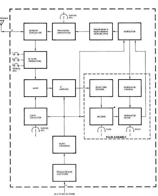
The output of the preselector is combined with the local oscillator output in the mixer. The mixer consists of a coaxial directional coupler and a crystal. The directional coupler isolates the local oscillator output from the antenna and directs it to the mixer crystal. The local oscillator is a re-entrant cavity type which uses a planar triode to generate the signal required to operate the mixer.
The intermediate frequency amplifier is a high
gain amplifier composed of an input stage, five amplifier stages and a
video amplifier. The amplified video output is fed to the pulse form
restorer circuits which prevent a ranging error due to variations in
receiver input signal levels, and also provides a standard amplitude
pulse to the decoder for each input signal exceeding its triggering
threshold. The decoder determines when a correctly ceded signal is
received and supplies an output to the modulator driver. The type code
to be accepted is selected by the CODE switch. Single pulse, two pulse,
or three pulse codes may be selected. The modulator driver and control
circuits initiate and control triggering of the transmitter modulator.
The modulator driver supplies two fixed values of overall system delay.
The desired delay is selected by the position of the DLY switch. The
modulator control furnishes the trigger and turn-off pulse for the
modulator and limits modulator triggers to prevent the magnetron duty
cycle from being exceeded, regardless of the interrogating signal
frequency. The modulator circuit employs silicon controlled rectifiers
which function similar to a thyratron, but
require a much shorter recovery time.
The associated modulator pulse forming network and transformer provide the necessary pulse to drive the transmitter magnetron. The desired pulse width is selected by the internal connections made to the pulse forming network.
The transponder power supply consists of input line filters, a series regulator, and a de-de converter. The power supply furnishes the required regulated output voltages with the unregulated input voltage between 21 and 30 vdc. The converter employs a multivibrator and full wave rectifier circuits.
The output of the transmitter is applied to the power divider via the circulator. The power divider gives equsl transmission power to the three helical antenna radiating elements.
The DCS provides a discrete link between ground command and the ATDA. The discrete link enables the ground command to control the operation of the various ATDA systems. The command transmissions from the ground are received and decoded by the DCS and are used to operate DCS relays that control power directly or energize relays ih the ATDA that determine equipment usage. During pre-launch the DCS is used for pad checkout of the ATDA systems. Discrete commands are sent to the ATDA via the DCS and their execution is verified from instrumentation data.
The uhf ascent and the uhf whip antennas are used for the reception of DCS ground commands during pre-launch and lift-off through ATDA separation. At separation coaxial switch 3 changes DCS reception from the uhf ascent antenna to the uhf stub antenna. The two diplexers permit the use of a common antenna for reception of DCS commands and telemetry transmissions.
The DCS consists of a receiver-decoder and three relay units. The receiver-decoder contains two uhf receivers and the decoder. The two receivers are redundant, and the system will operate properly if only one receiver is functioning. Each of the three DCS relay units contains eight magnetically latched relays. Each relay is set or reset by a DCS command.
The DCS receives phase shift keyed frequency modulated signals composed of a reference and an information signal. The information signal is in phase with the reference for a logical I and 180 degrees out of phase with the reference for a logical 0, thus establishing the necessary requirements for digital data.
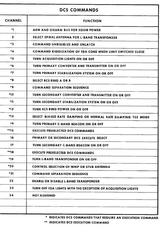
The ground command to the DCS is a 12-bit message. Each bit consists of five sub-bits. The five sub-bits are coded to represent a logical 1 or 0. The first three bits of each message is the vehicle address. The second three bits of the message is the system address specifying real time command. The last six bits in the message contain a five-bit relay number and a one-bit relay set-reset discrete command. Table 15-1 lists the DCS channels and contains a brief description of their function.
The DCS uses two types of commands. One type command is executed the moment it is received. This type command operates DCS channel relays which directly control power to the selected ATDA system. Power is applied in the set condition and removed in the reset condition.
The other type command is received but not immediately executed. These commands operate DCS channel relays that connect the control circuits of selected ATDA systems to a pulse bus. The commands are executed when the pulse bus is energized by an execution command. The channels marked by an asterisk in Table Below indicate the DCS commands which require an execution command.
A block diagram of the DOS receiver-decoder is shown in Figure Below . Basically, the block diagram consists of a receiver, a decoder, and a power supply command to both sections.
Digital Command System Block Diagram
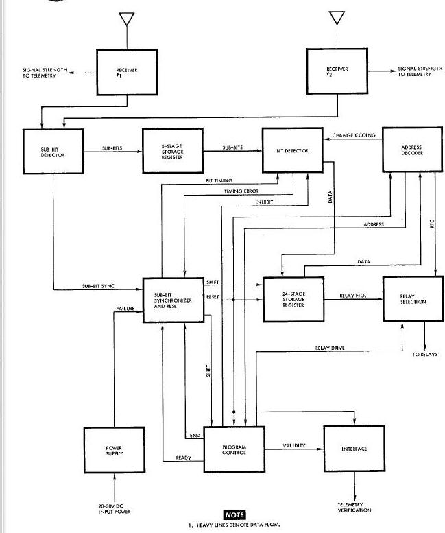
The audio outputs of the two receivers are linearly summed in an emitter follower of the sub-bit detector module. The sub-bit detector converts the audio to subbits. The 5-stage shift register provides buffer storage for the output of the sub-bit detector. The states of the five stages of the shift register represent the sub-bit code. When a proper sub-bit code exists in the shift register, the bit detector produces a corresponding I or 0 bit. The output of the bit detector is applied to the 24-stage shift register.
The sub-bit synchronizer counter produces a synchronizing bit output for every five sub-bits. The synchronizing bit is used to gate the 2-stage shift register.
When a message is received, the vehicle address
is inserted into the first three stages of the 24-stage shift register.
If the vehicle address is correct, the vehicle address decoder circuit
will produce an output to the bit detector which changes the acceptable
sub-bit code for the remainder of the message. The next three bits of
the message, the system address, are inserted into the first three
stages of the 2-stage shift register, displacing the vehicle address to
the next three stages. The system address decoder circuit identifies the
specific address and sets up the DCS to handle the remainder of the
message.
When the system address is a real time command, the message is inserted into the first six stages of the 24-stage shift register and the system address and vehicle address are shifted into the next six stages. The real time common selection circuit recognizes the first stage of the 24-stage shift register to be a relay set or reset function and will apply a positive voltage to set or reset all relay coils, as applicable. The real time command selection gates select the proper relay from the relay number stored in the 24-stage shift register and provides an output which applies power to the coil of the selected relay.
Upon completion of data transfer or if the system to which the data was transferred fails to respond within 100 milllseconds, the DCS will reset in preparation for the next message. The DCS will also reset in the event of a timing error in transmission of data, or if the DCS power supply voltages become out of tolerance.
The DCS power supply operates from the ATDA main power bus and supplies the receivers and decoder with regulated dc voltages.
A verification signal is supplied by the decoder for telemetry transmission when a ground command has been received.
Transmission of instrumentation data is accomplished by the telemetry transmitters. Operation of the transmitters is controlled by the ground station via DCS channels 6 and 10. An interlock in the ATDA prevents both transmitters from operating at the same time.
Coaxial switches select the antenna used for telemetry transmission. The uhf ascent and uhf whip antennas are used during pre-launch checkout and lift-off through ATDA separation. After separation the output connection of coaxial switch 3 is switched from the uhf ascent antenna to the uhf stub antenna.
Data from the Instrumentation System programmer is supplied to the telemetry transmitters in non-return-to-zero pulse code modulated pulse trains. The transmitters relay the information to the ground stations in a digital format composed of l's and O's at a rate of 51.2 kilobits per second. The carrier frequency is deviated to the higher frequency deviation limit in order to transmit a 1 and to the lower deviation limit to transmit a 0. The Figure Below is a block diagram of the telemetry transmitters. The transmitters operate on the same frequency and are identical in operation.
Telemetry Transmitter Block Diagram
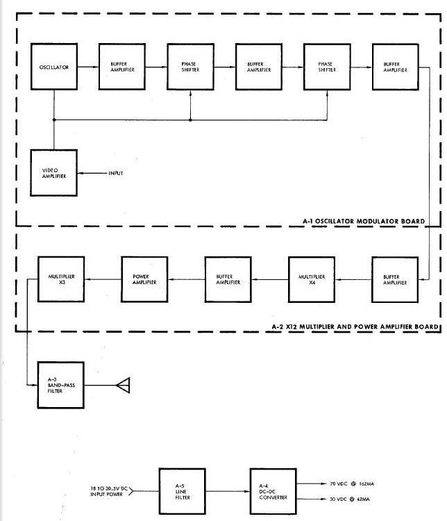
The input signal is amplified by the video
amplifier and is used to modulate the Output of the oscillator. The
oscillator is crystal controlled for good frequency stability. The
modulated signal is passed through a series of buffer amplifiers and two
phase shifters. The buffer amplifiers increase the signal level and
isolate the crystal circuit from the frequency multipliers. The phase
shifters
provide impedance matching of the crystal oscillator to improve signal
linearity for large deviations in frequency.
A times-four multiplier, a power amplifier, and a times-three multiplier increase the carrier frequency and power to the desired output values. The bandpass filter minimizes spurious radiations at the output of the transmitter.
The line filter prevents noise on the input power bus from affecting transmitter operation and prevents transients generated within the transmitter from feeding back to the input power bus.
The transmitter dc-dc converter is a completely encapsulated unit employing transistors, diodes and a transformer to provide regulated outputs of 30 vdc and 70 vdc from unregulated input voltage of 18 to 30.5 vdc. The converter is a constant power input type, thus minimizing the heat dissipation caused by high voltage inputs.
The three uhf antennas (ascent, stub and whip)
provide simultaneous transmission for the telemetry transmitters and
reception for the DCS receivers. The uhf ascent antenna is used during
pre-launch for pad checkout and from lift-off until ATDA separation. The
uhf stub antenna gives directional roll coverage after ATDA separation.
Switching from the ascent antenna to the stub antenna is
accomplished by coaxial switch 3 at ATDA separation. The uhf whip
antenna provides omnidirectional yaw coverage and is used from
pre-launch throughout the mission. The antennas have a
quarter-wavelength radiation pattern.
The uhf ascent antenna (Figure Below) is mounted on the Target Docking Adapter cone where it is protected from wind blast and launch temperatures during lift-off by the ascent shroud.
UHF Ascent, Stub, and Whip Antennas Diagram
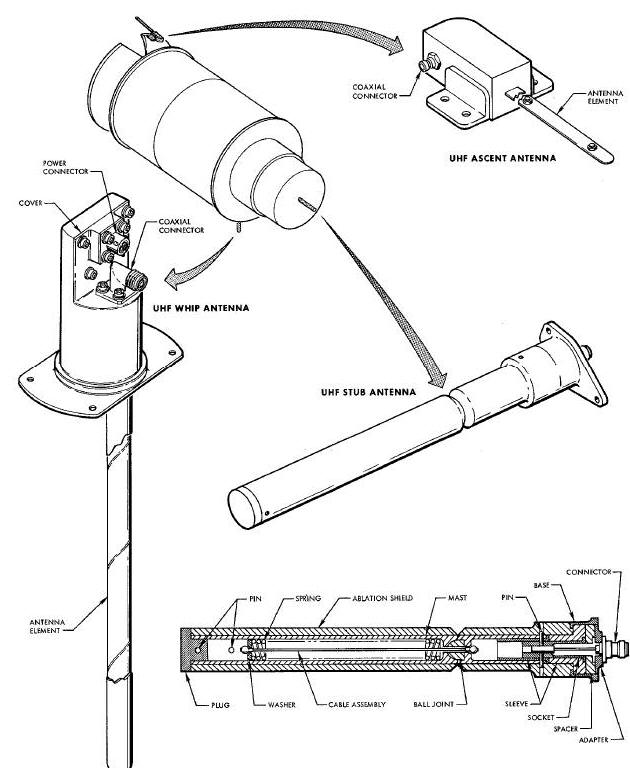
The uhf ascent antenna is approximately 16
inches long. The antenna element consists of two 1/2-inch wide
gold-plated steel blades which are bolted together. For rigidity, the
antenna element is shaped in a 0.5 inch wide arc having a radius of 1.5
inches. The two laminations of steel blades, compounding a single
antenna element, are rigidly secured together with nuts and bolts at the
top
and bottom.
The uhf stub antenna, physically constructed as illustrated in Figure Above, is mounted on the battery module. The antenna protrudes aft from the battery module into the forward section of the launch vehicle. This protects it during the boost phase of the mission.
The antenna consists of a mast and base which
weighs approximately 1.1 pounds. The mast is constructed of 3/4-inch
cobalt steel machined to tubular form, and covered by a Teflon ablation
shield. The antenna is approximately 13.5 inches long including the
connector, and 1.25 inches in diameter over the ablation material. The
radiating length of the antenna is approximately 11.2 inches long. The
mast consists of two sections. The front section is mounted on a cobalt
steel ball Joint and retained to the rear section by a spring loaded
cable. Electrical contact between the mast sections is made through the
ball Joint and the spring loaded cable assembly. The ball Joint allows
the front section of mast to be deflected to approximately 90 degrees in
any direction around the antenna axis.
The spring of the cable assembly is preloaded to approximately 45 pounds
to \cause the front section, when deflected, to return to the erected
position.
The rf connector is press fitted into a socket and makes contact to the mast through the socket and sleeve, which are the same material as the mast. The shell of the rf connector is mounted to the base which is isolated from the mast by a Teflon spacer and sleeve.
The uhf whip antenna is mounted on the equipment
section of the ATDA. The whip antenna is extended during pre-launch and
is used throughout the mission. A fiberglass fairing protects the
antenna from damage during launch.
The antenna element (Figure Above) is a tubular device made from a 2-inch wide beryllimm copper strip processed in the form of a tube. The antenna forms an element that is approximately 9.2 inches long and i/2 inch in diameter.
C-Band Antennas and Power Dividers
Two sets of C-band helical antenna supply the transmission and reception capability for the C-band radar beacons. Each set of helical antennas consists of three radiating elements (antennas) and a power divider. The three antennas have a radiation pattern with three symmetrically located lobes. Two of the lobes are oriented toward the earth when the ATDA is roll-stabilized in flight.
The C-band helical antennas (Figure Below) are mounted on the equipment section flush with the outside skin of the ATDA and spaced 120 degrees apart. Each antenna unit is approximately 3.4 inches long, 1.8 inches wide, has a depth of 2.21 inches over the connector, and weighs approximately 3.5 ounces.
C-Band Antennas, Diplexers, And Coaxial Switches Diagram
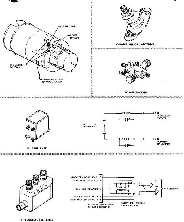
The power divider (Figure Above) measures approximately 3.86 inches over the connectors, 4.0 inches over the tuning knobs, and weighs about 6.5 ounces.
The power divider is basically a cavity type power splitter. During beacon transmission, power is delivered to the power divider where it is divided equally among the C-band radiating elements. The power divider contains a double stub tuner to compensate for mismatch between the C-band beacon and the C-band radiating elements. Tuning is accomplished by means of a self-locking timing shell located underneath each tuning stub cap.
The two uhf diplexers provide isolation between the DCS receivers and the telemetry transmitters to permit the use of a common antenna for both transmission and reception. The diplexers are located in the ATDA equipment section. The physical representation and a schematic of the diplexers is illustrated in the Figure Above.
The diplexer is approximately 4.5 inches wide, 4 inches high, and 2.7 inches deep, contains two input and one output connectors, and weighs approximately 1.25 pounds. Each channel consists of a high Q cavity, tuned to the corresponding operating frequency. All channels are isolated from each other without appreciably attenuating the rf signals passing through it. Each channel can be re-tuned if the assigned operating frequency is changed.
The three coaxial switches permit antenna and transmitter/receiver selection. The coaxial switches are located in the ATDA equipment section. The physical construction and approximate location of the coaxial switches is illustrated in Figure Above.
Coaxial switch 1 is used for antenna selection for the primary telemetry transmitter.
Coaxial switch 2 is for antenna selection for the secondary telemetry transmitter.
Coaxial switch B provides antenna selection for one of the DCS receivers and either of the telemetry transmitters.
Each switch contains a power connector, an input connector, two output connectors, and weighs approximately 0.5 pounds. The dimensions of each switch are approximately 2.65 inches long, 1.82 inches high, and i inch wide. The three coaxial switches are identical and may be used interchangeably. Basically, the coaxial switches supply single-pole double-throw switching action as illustrated in Figure 15-13. The switch, having a 20 millisecond maximum operation time, operates on 3 amperes at 28 vdc and uses a latching solenoid break-before-make switching action. The coaxial switches are designed to operate from 15 mc to 500 mc, and from 5500 mc to 5900 mc. Pins A and B of each switch are utilized to accomplished the switching action.
The two C-band radar beacons supply the tracking capability for the ATDA. The two radar beacons are transponders which transmit a reply when properly interrogated. The beacons are located in the equipment section of the ATDA. Each beacon consists of a superheterodyne receiver, a decoder section, and a transmitter. The receivers are tuned to a center frequency of 5690 megacycles and the transmitters to 5765 megacycles. The transmitter peak power output is 500 watts minimum to the antennas. Code spacing for the beacons is 3.0 microseconds. The C-band beacon is a sealed unit and measures approximately 9.34 inches by 8.03 inches by 3.26 inches. As illustrated in the Figure Below , the beacon has a power and test connector, an antenna connector, and a crystal current test point connector. The beacon contains external adjustments for local oscillator, preselector (rf filter), and transmitter tuning switches for selecting the desired interrogation code; and one of two preset transponder fixed delay times. These adjustments and switches are accessible by removing pressure sealing screws. The beacon employs solid-state circuitry, except for the transmitter magnetron and receiver local oscillator.
C-Band Beacon and Telemetry Transmitters Diagram
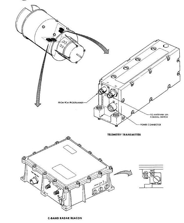
The telemetry transmitters provide the instrumentation data transmission capability. The telemetry transmitters are located in the ATDA equipment section. The physical construction and approximate location of the telemetry transmitters is illustrated in Figure Above .
The two telemetry transmitters are identical. They weigh about 41 ounces and are 2.75 inches high, 2.25 inches wide and are 6.5 inches long. Each transmitter contains adc power connector, an rf output power connector, and a video input connector.
The telemetry transmitters are solid-state frequency modulated transmitters. Each transmitter consists of an oscillator-modulator, a times-12 (x12) multiplier and power amplifier, a bandpass output filter, a line filter and a dc-dc converter. After a 30-second warm-up, the transmitters are capable of continuous uninterrupted operation for 500 hours. The transmitters operate at 246.3 megacycles with 2.0 watts minimum power output. Peak carrier frequency deviation is + 150 kilocycles.
The DCS consists of a receiver-decoder and three relays and supplies the link for ground commands to the ATDA. The DCS components (Figure Below) are located in the equipment section of the ATDA.
DCS Receiver/Decoder and Relay Boxes Diagram
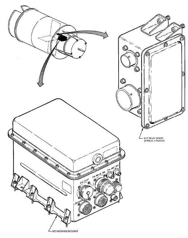
The two DCS receivers operate on a fixed frequency in the 406-450 megacycle range. Each receiver consists of a preselector, local oscillator and multiplier, two intermediate frequency strips, a discriminator, and an output audio amplifier. The decoder contains a sub-blt detector, a bit detector, an address decoder, a 5-stage and a 24-stage storage register, relay selection circuits, and a synchronizing and reset circuit.
The receiver-decoder package is approximately 8 inches high, 8 inches wide, and 12 inches long. The relay boxes are identical. Each relay box is approximately 2.25 inches wide, 5 inches high, and 3 inches deep. The combined weight of the receiver-decoder package and the relay boxes is approximately 23 pounds. The receiver-decoder package contains two uhf receivers and a decoder while each of the relay boxes contain eight relays.
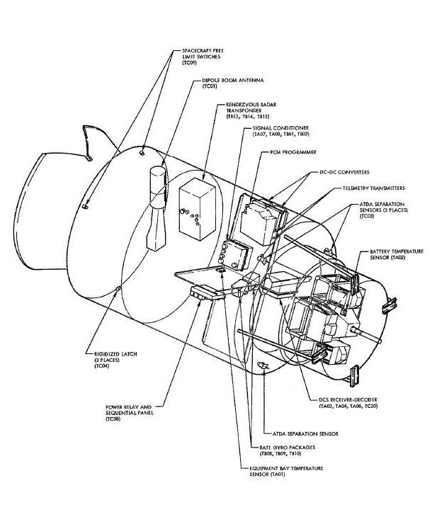
The Instrumentation System provides a means of
data acquisition with respect to the progress and condition of the ATDA.
Data acquisition in the ATDA is the sensing of specific conditions or
events on board the ATDA and displaying the data derived from these
inputs to ground operation personnel. In this respect the data
acquisition is shared by all ATDA systems and the ground operation
support system.
The basic components of the Instrumentation System are: temperature sensors, signal conditioners, dc-dc converters, and a programmer. The location of the Instrumentation System components and various signal monitoring points are illustrated in the Figure Below.
Instrumentation System Diagram
The Instrumentation System supplies 43 parameters (measurements) to the ground station. The system primarily monitors ATDA system parameters. These parameters are used for determining the progress of the ATDA and the performance of the various systems, and for making decisions concerning mission safety and success. During pre-launch checkout of the ATDA, ground commands are given and their execution is verified from instrumentation data. Equipment status and sequential switch positions are monitored to insure all ATDA systems are in lift-off configuration. During the orbital phase of the mission, the Instrumentation System supplies real-time telemetry information while the ATDA is within range of the ground station.
The Instrumentation System is controlled by ground commands via the Digital Command System (DCS). DCS channel 6 is used to apply main bus power to the primary dc-dc converter and telemetry transmitter; while channel i0 controls power to the secondary converter and telemetry transmitter. An interlock in the wiring arrangement of the power control relays (K33-I and EB3-2) prevent application of power to the primary and secondary units simultaneously. A block diagram of the ATDA Instrumentation System is illustrated in the Figure Below .
Instrumentation System Block Diagram

The Instrumentation System obtains data from temperature sensors, pressure transducers, switch and relay actuations, and various monitoring points in the ATDA systems. The majority of the signals obtained are compatible with the multiplexing and encoding equipment without alteration. Some of the signals, however, are routed to a signal conditioner where their characteristics and/or amplitudes are changed. The resulting signals, as well as those from other sensors, are of three basic types: low-level (0 to 20 millivolts de), high-level (O to 5 vdc), and bi-level (0 or 28 vdc). The programmer combines and converts these inputs into a serial binary-coded digital signal and supplies it to the telemetry transmitters.
The basic functions of the Pulse Code Modulated (PCM) programmer are: data multiplexing; timing, to support the multiplexing functions; and analog to digital conversion. The output of the programmer to the transmitter is a pulse code modulated pulse train. A block diagram of the PCM programmer is illustrated in Figure Below .
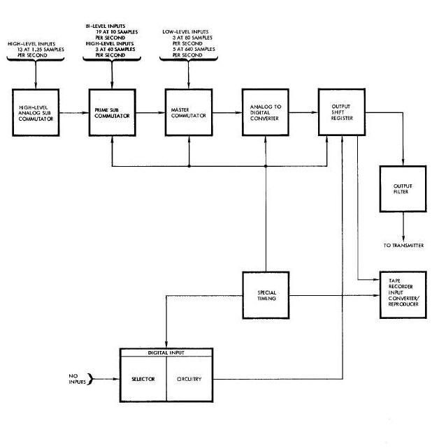
The basic components of the programmer are a high-level analog subcommutator, prime subcommutator, master commutator, analog to digital converter, output shift register, digital input selector and input circuitry, special timing, output filter, and tape recorder input converter/reproducer.
The programmer high-level analog subcommutator samples 13 high-level inputs at 1.25 samples per second. The analog subcommutator receives its inputs directly from the signal sources, or from the signal conditioner. The output of the analog subcommutator is applied to the prime subcom_utator for further multiplexing.
The prime subcommutator, in addition to accepting the sampled high-level analog subcommutator data output, samples 19 bi-level signals at 10 samples per second, and 3 high-level signals at 40 samples per second. The prime subcommutator supplies its output to the master commutator.
In addition to accepting the inputs from the prime subcommutator, the master commutator samples 5 low-level signals at 640 samples per second and 3 low-level signals at 80 samples per second. The output of the master commutator is applied to the analog to digital converter where the analog output from the master commutator is converted to digital data.
The digital data from the output of the analog to digital converter is applied to the output shift register which provides a continuous non-return-to-zero PCM pulse train of 51.2 kilobits per second. The output of the output shift register is applied to the telemetry transmitter through the output filter.
Timing of all operations in the PCM programmer is provided by the special timing circuits. Two crystal controlled oscillators and a series of counters are used to supply the gate pulses which determine the sampling rates of the programmer.
The digital input selector and input circuitry and the tape recorder input converter/reproducer components are not utilized during ATDA operation. The Instrumentation System does not sample digital data or record data for data-dump transmission.
The output signal from the PCM programmer is a 51.2 kilobit non-return-to-zero signal with a voltage that is adjustable between 0.1 volt and 1.0 volt peak. The serial output has positive voltage for a i and zero or negative voltage for a 0.
A brief description of all ATDA instrumentation parameters is contained in the following paragraphs. The parameters are described in groups identified by their applicable data source system. Data flow from the signal source to the programmer is illustrated in the Figure Above .
The Instrumentation System monitors six Sequential System parameters. The sequential parameters are hi-level signals originating from switch or relay actuations and are supplied directly to the PCM programmer.
During pre-launch checkout of the ATDA, latch relay monitor (TC08) indicates that all control latch relays are in the sequential mode required for launch condition. When all control relays are latched or reset in the proper position a 28 vdc signal is applied to the PCM programmer. One or more relays in an abnormal mode reduces this signal to 0 vdc.
With the ascent shroud installed, a 24 vdc signal is applied to the PCM programmer. At shroud Jettison (TC05), the 24 vdc circuit is broken thus reducing the voltage applied to the programmer to 0 vdc. A 24 vdc signal is supplied to the PCM programmer to indicate ATDA separation (TCO3). This signal results when any two of the three separation sensor switches close.
Unrigidize/latches reset (TC21) indicates the Target Docking Adapter cone is unrigidized and all latches are reset. When this condition exists a 24 vdc signal is supplied to the PCM programmer. Rigidized (TC04) is obtained from three rigidized limit switches which close when the rigidized limit is reached. When all three limit switches are closed a 28 vdc signal is applied to the PCM programmer. Spacecraft free (TC09) indicates whether or not physical attachment exists between the A_DA and the spacecraft. A 24 vdc signal is fed through one or both of two limit switches to the PCM programmer when complete attachment does mot exist.
The Electrical System supplies the ground station with 8 parameters which indicate the condition of the ATDA batteries. Five of the signals are routed through the signal conditioner to make them compatible with the PCM programmer circuits.
Battery temperature (TA02) indicates the battery case temperature. A resistive element temperature sensor mounted on the battery supplies the low-level signal to the PCM programmer.
Squib bus safe (TC06) and squib bus armed (TC07)
are bi-level signals applied to the PCM programmer which indicate the
position of the squib control relays. When all relays that control power
to squib igniters are deenergized (TC06) a 24 vdc signal is obtained.
When any of these relays are energized it removes the 24 vdc signal from
the PCM programmer. When one or more of the squib control
relays are energized (TC07) a 24 vdc signal is applied to another
channel of the PCM programmer.
Main bus current (TA05) is used to monitor the total current being drawn from the batteries. The signal originates from a 50 millivolt shunt installed at the main bus. The signal is routed to the signal conditioner which provides a low-level signal output to the PCM programmer.
Main bus voltage (TB03), control bus voltage (TB04), squib bus i voltage (TB05), and squib bus 2 voltage (TB06) are measured to supply the ground station with information relative to battery condition. The high-level signals are routed through the signal conditioner before being applied to the PCM programmer.
TARGET STABILIZATION SYSTEM PARAMETERS
The Instrumentation System monitors four parameters from the Target Stabilization System. These signals are high-level signals conditioned by the signal conditioner prior to being applied to the PCM programmer.
AC voltage (TS07) gives an indication of the output of the inverter that is in operation. Pitch, roll, and yaw rates (TB08, TB09, TSIO) are monitored to allow evaluation of the rate control portion of the Target Stabilization System. Primarily and secondary rate package signals are monitored on the same telemetry channel, depending on which system has been selected by the DCS.
DIGITAL COMMAND SYSTEM PARAMETERS
The DCS supplies four parameters for ground monitoring. These signals provide information relative to the operation of the DCS. Three of the four signals are low-level signals.
Receiver i signal strength (TAO3) and receiver 2 signal strength (TA04) give an indication of the strength of the signals received by the receivers in the DCS.
DCS validity (TA06) is monitored to indicate that a command signal was received by the DCS receiver-decoder. DCS pulse bus (ON-OFF) (TC20) indicates that power is applied to the DCS execute circuitry. A 28 vdc hi-level signal from the DCS pulse bus is applied to the PCM programmer each time the pulse bus is energized by a ground command.
REACTION CONTROL SYSTEM PARAMETERS
Five parameters from the Reaction Control System
are monitored to indicate the condition of the system. Reaction Control
System ring A/B (TC10) is a hi-level signal that indicates which
thruster ring is energized. A 28 vdc signal to PCM programmer indicates
ring A operation; 0 vdc indicates ring B operation. Thruster firing, TCA
1 through 8 (TCII through TCI8), are bi-level signals are are monitored
to indicate proper operation of the Reaction Control System, Bi-level
pulse signals of 0 or 28 vdc are derived from the solenoid command
signals. A 0 vdc signal indicates thruster firing. Regulated nitrogen
pressure (TBI2) is a high-level signal obtained from a
potentiometer-type transducer to indicate the pressure (0-500 psi) of
the Reaction Control System regulated nitrogen.
Ring A and B nitrogen source pressure (TBI6, TBIT) parameters indicate the source pressure in each nitrogen supply. The pressure is measured by a potentiometer-type pressure transducer which is a part of the Reaction Control System.
RENDEZVOUS RADAR TRANSPONDER PARAMETERS
To monitor the operation and environmental condition of the rendezvous radar transponder, four parameters are relayed to the ground station. A temperature transducer installed in the transponder supplies a high-level signal output for transponder case temperature (TBL4).
Beam (dipole) antenna extended (TCO1) is monitored for operational reliability. An output of 28 vdc from the boom actuator indicates the antenna is extended. An output of 0 vdc indicates the antenna is not fully extended. Antenna selection (TBIS) indicates spiral or dipole antenna usage. Selection of the antenna is governed by the strength of the interrogating signal. An output of 1.O to 5.0 vdc indicates dipole antenna usage and O to Ou 5 vdc indicates spiral antenna usage.
Transponder rf power (TBI3) is a high-level signal that indicates when the high voltage power supply in the radar transponder is energized. As long as the transponder receives interrogation signals the high-voltage power supply is energized. Loss of the interrogating signals deenergizes the power supply. An output of 2 to 5 vdc indicates an on condition, and an output of 0 to 0.5 vdc indicates an off condition.
INSTRUMENTATION SYSTEM PARAMETERS
To insure proper scaling is being employed by
the Instrumentation System, four parameters are monitored. These
reference signals, low-level full-scale (TA07), low-level zero (TA08),
high-level full-scale (TB02), and high-level zero (TB01) are outputs of
the dc-dc converter that have been conditioned by the signal
conditioner. The data received from these parameters provide the ground
station
verification that the Instrumentation System is functioning properly.
Equipment bay temperature (TA01) is the only structural parameter monitored and indicates the temperature that exists within the equipment bay. The temperature is measured by a resistive-element temperature sensor which supplies a low-level signal to the PCM programmer.
The two temperature sensors are resistive-element, surface-mounted, sensors that convert the temperature into directly proportional electrical signals. The sensing elements are fully-annealed pure-platinum wire encased in ceramic insulation in a strain-free manner to provide maximum stability.
The physical construction of the sensors and a
typical schematic is illustrated in the
Figure Below. The sensors are approximately 0.4 inches by 0.75
inches by 2.0 inches and weighs a maximum of 0.075 pounds. They have a
temperature range of 0 to 400 degrees Fahrenheit and provide a 0 to 20
millivolt dc output. One of the temperature sensors is mounted on the
battery case and the other in
the equipment section at the intersection of the equipment support
assemblies.
Signal Conditioner & Temperature Sensor Diagram
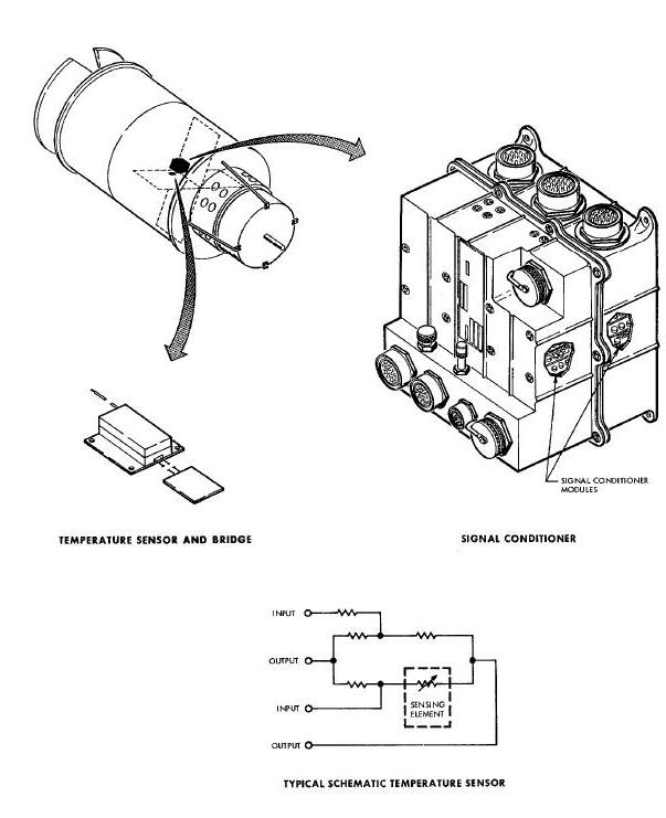
The signal conditioner is approximately I0 inches by i0 inches by 8 inches and weighs about eight pounds. The signal conditioner is located in the equipment section of the ATDA. Figure Above illustrates the physical construction of the signal conditioner.
The signal conditioner contains 12 signal conditioning modules: one ac voltage monitor; four dc voltage monitors; one dc millivolt monitor; three attenuators; and three phase sensitive demodulators. The modules are constructed on circuit boards using printed wiring techniques.
The ac voltage monitor accepts a signal ranging from 23 to 29 volts rms over a frequency range of 380 to 420 cycles. The output is from 0 to 5 vdc, varying only with the input voltage.
The four types of dc voltage monitors are designed to accept various positive and negative dc voltage inputs and provide outputs of 0 to 5 vdc. The de millivolt monitor accepts an input of 0 to 50 millivolts and provides a proportional output of O to 20 millivolts.
There are three types of attenuator modules. These modules have various dc inputs which are attenuated to the 0 to 20 millivolt range or the 0 to 5 vdc range. Some attenuator modules contain two data channels.
There are three variations of the phase sensitive demodulators. Basically, the phase sensitive demodulator accepts two input voltages: one signal voltage and one reference. It provides a dc output of five volts for a full scale input signal that is in phase with the reference and an output of 0 volts for a full scale signal that is 180 degrees out of phase with the reference.
The two dc-dc converters supply the
Instrumentation System with regulated dc voltages of +5 and +/- 24 vdc.
The converters are essentially voltage regulators which operate on 18 to
30.5 vdc and supply regulated outputs. The dc-dc converters (Figure
Below 15-20) are approximately 5.5
inches by 5.5 inches by 7 inches3 and weigh about seven pounds each. The
converters are located in the
ATDA equipment section.
DC-DC Converter and PCM Programmer Diagram
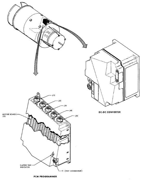
The PCM programmer is located in the equipment section of the ATDA and encodes all instrumentation data for transmission. The programmer weighs approximately 20 pounds and is 11 inches by 11 inches by 4.5 inches. (Figure Above ).
The programmer is composed of 16 subassemblies. Thirteen of the subassemblies are multilayer printed-circuit boards (mother-boards) constructed of a glass-epoxy based material laminated at high temperatures. Most of the programmer subassemblies are embedded in polyurethane foam to provide rigidity and damping. An elapsed time meter indicates total operating time.
Two telemetry transmitters transmit the Instrumentation System data to the ground stations. Although the transmitters serve the Instrumentation System, the antennas and associated switching are part of the Communication System; therefore, the transmitters are described in detail in Section XV, Communication System.
PYROTECHNIC DEVICE S AND SEPARATION ASSSMEMBLIES
The pyrotechnic devices and separation assemblies (Figure Below), installed in the Augmented Target Docking Adapter (ATDA), are used to execute events initiated by the Sequential System. The events executed by these devices, in sequential order, are: release the shroud retaining bands; Jettison the ascent shroud, sever the ATDA/launch vehicle mating ring, separate the ATDA from the launch vehicle and activate the Reaction Control System (RCS).
Pyrotechnic Devices and Separation Assemblies Diagram
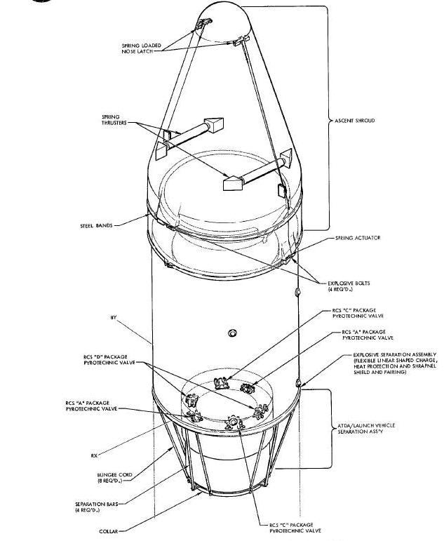
The pyrotechnic devices and separation
assemblies which perform these functions
and the events executed by them are as follows:
-
Explosive bolts - release shroud retaining bands.
-
Shroud separation assembly - separate and Jettison the shroud.
-
Flexible Linear Shaped Charge - sever the ATDA/launch vehicle mating ring.
-
ATDA/launch vehicle separation assembly - provide a separation velocity between the launch vehicle and the ATDA.
-
Pyrotechnic valves - open lines and activate the RCS.
Explosive bolts (Figure Below) are located at four points on the ATDA. Two bolts secure the steel retaining bands around the shroud. The other two bolts secure the base of the shroud at the separation line. When initiated by the Sequential System, the bolts explode, releasing their respective clamps and allowing the separation assembly to Jettison the shroud.
Pyrotechnic Valves and Explosive Bolts Diagram

The bolts are electrically connected to the Sequential System via two cables. The cables are located 90 degrees from the shroud separation line, near the base of each segment.
The four identical explosive bolts are five inches long, 5/8 of an inch in diameter and are made of stainless steel. A deep cylindrical cavity is machined into each end of the bolts. The cavities extend in approximately two inches from each end of the bolt. A solid part in the center is not drilled out. The end of each cavity is tapped to receive the threaded electrical detonator. The bottom of each cavity is so designed that the explosive blast will cause the bolt to break or fail at the central solid part as though sheared off there.
The detonators used are of the bridge wire type.
Redundancy is maintained by using two detonators per bolt. A sleeve is
slipped over the outside of the bolt and held in a center position with
set screws. The sleeve maintains the parting planes of each bolt outside
the clamps which it holds in place, and prevents any bolt fragmentation
from piercing the shroud.
When the shroud Jettison squib fire relays
connect squib bus power to the eight shroud explosive bolt detonators, a
current sufficient to set off the ignition mix, flows in the bridge
wire. The energy frcm the ignition mix detonates the Penta Erythritol
Tetra Nitrate (PETN) explosive charge next to it. The stress which the
explosion puts upon the bolt structure causes the hollow parts on each
side to break away frcm the central solid part.
Six pyrotechnic valves (Figure
Above) are installed in the RCS. Three valves are used in each ring,
one valve for each package. Each ring has a fuel package (called the "D"
package), an oxidizer or "C" package, and a pressurant or "A" package.
The valves isolate the fuel, oxidizer and pressurant from the rest ofthe
RCS by keeping them in their respective supply tanks. When the valves of
either A or B ring are actuated, pressurant is released into the fuel
and oxidizer tanks, and fuel and oxidizer are forced into lines to the
eight
activated thrusters. The pyrotechnic valves are one-time actuating
devices which control the flow of these fluids.
Two types of valves are installed in the RCS. Both are normally closed. One type however is replaceable, the other is not° The RCS package "A" uses the no replaceable type. The RCS packages "C" and "D" use the replaceable type. If a nonreplaceable valve is defective, or if the squib has been fired, the package must be changed. Replaceable valves can be changed individually without chapping the whole package.
A pyrotechnic valve consists of a cartridge, a
valve body, one or two nipples, a ram, a seal and a screw. The
replaceable valve uses one closed-end nipple which is installed within
the valve body and welded into place. The nipple is in the line from the
supply. As long as the nipple is intact, it blocks the fluid from the
supply. The nonreplaceable valve has two closed-end nipples butted
together; one is the inlet, the other is the outlet port. The ram is in
a slot or channel in the valve body, indexed directly above the centers
of
the nipples. The seal and screw are in the head of the ram. The
cartridge is in the valve body at the top of the ram head. The function
of the seal is to prevent blow-by of the actuation gas. The function of
the cartridge is to generate the energy to drive the ram. The ram has
two functions. One is to shear off the nipples and open the lines. The
other is to complete the line
by aligning the hole in its body with both sides of the llne.
At Vernier Engine Cut-Off (VECO) plus 12
seconds, the squib buses are connected to six squibs on the three
pyrotechnic valves of RCS ring B. Each valve operates in an identical
manner. The squib sets off the cartridge which generates sufficient gas
pressure to drive the ram. The ram is propelled along the channel, and
the ram head shears off the nipples in its path. As the ram comes to
rest at the
opposite end of the channel, a hole through its body is aligned with the
lines once blocked by the nipples. Fluid flows freely from the supply
tank through the lines.
This same process is repeated on RCS ring A the first time this ring is selected by a Digital Command System (DCS) command.
The Flexible Linear Shaped Charge (FLSC) is the pyrotechnic device which severs the ATDA/launch vehicle mating ring. The FIASC is shown in cross section in the Figure Below . The FLSC is a V-shaped flexible lead sheathing containing a core of cyclonite (RDX) high explosive. The specific type, shape and thickness of the material to be severed by a FLSC dictates the amount of explosive to be used. In this explosive separation assembly, dual strands of FLSC are used.
Mechanical Separation Assembly Diagram
The FLSC assembly consists of three detonator blocks, three crossovers, three dual boosters, a molded backup retainer and a back blast shield. Single bridge wire detonators are used in two detonator blocks, a double bridge wire in the third. In each detonator block, the crossovers are next to the detonators, and the boosters are next to the crossovers. The crossovers apply the shock wave to the booster. The booster propagates the shock wave to the FLSC to insure detonation of both strands.
When the explosive separation assembly is installed, the dual FLSC is attached to the periphery of the ATDA/launch vehicle mating ring. The open portion of the V-shaped FLSC is placed toward the surface to be cut.
The detonator blocks are installed on the inside of the mating ring and extend through the skin into the FLSC molded backup retainer. The detonators are wired to the ATDA shaped charge and RCS ring B squib fire relays. The back blast shield surrounds the molded backup retainer and is attached to it. A fiberglass fairing covers the retainer, shield and FLSC to protect the explosive separation assembly from aerodynamic heating.
At VECO plus 12 seconds, the Sequential System connects the squib buses to four ATDA shaped charge igniters, setting them off. The igniters detonate the crossover, the crossover detonates the boosters, and the boosters detonate the redundant strands of FLSC.
As the FLSC detonates, the concussion collapses the sheathing in each V-groove. This directed action produces a cutting Jet of explosive products and minute metal particles. The Jet in turn produces extremely high localized pressures. The resulting stress is far above the yield strength of the ring material. The skin is severed and the ATDA is detached, permitting the mechanical separation assembly to operate.
The shroud separation assembly is designed to
Jettison the ascent shroud at the completion of the launch phase. The
shroud is held together by steel bands until after VEC0, then explosive
bolts are fired, releasing the steel bands and allowing the separation
assembly to function. The shroud is constructed in two segments, one
long segment (including the nose cone) and one short segment. When
Jettisoned, the shroud separates and falls away to the rear, one segment
on each side.
The shroud separation assembly (Figure Below) consists of two preloaded spring actuators; two preloaded spring thrusters; two pivots; two spring loaded nose latches; two elastic latch cords with ball detents; two pair of split anchor blocks; and two pair of steel bands and clamps (held together by explosive bolts). The spring actuators are mounted at the base of the shroud at the separation line. The spring thrusters are mounted just below the shroud center of gravity. The nose latches hold the upper end of the shroud together before Jettison, and unlatch to permit the segments to part at the nose. The elastic cords apply tension to the latch handles to keep the latches engaged. The ball detents on the cords are clamped in the anchor blocks to hold tension on the latches. The anchor blocks, which are compressed and trapped in the parting line by the tension of the steel bands, maintain tension on the latch cords. The base clamps, when pulled together by explosive bolts, compress the spring actuators and hold the shroud base in firm contact with the Target Docking Adapter (TDA). The entire assembly is held together by the steel bands, until the explosive bolts are fired by the Sequential System.
Shroud Separation Assembly Diagram
ATDA/IAUNCH VEHICLE SEPARATION ASSEMBLY
The ATDA/launch vehicle separation assembly (Figure Above) is used to release the ATDA from the launch vehicle and provide it with a separation velocity.
The separation assembly consists of the mating ring; a catapult, made up of eight bungee cords and attaching ring; and four separation rails. The mating ring structurally bonds the ATDA to the launch vehicle during ascent and provides a base from which the bumgee cords are suspended. The mating ring also provides a separation line where the two vehicles are severed pyrotechnically when orbit is achieved.
The catapult is elastically stressed to approximately 500 pounds and provides a separation velocity when the mating ring is severed. An attaching ring supplies a co, non surface for attaching the eight bungee cords which provide the thrust for the catapult. The attaching ring also provides a surface on which the battery module rests during launch. The bungee cord catapult is suspended from hangers on the underside of the mating ring.
Four separation rails span the RCS and battery module to guide the ATDA during the separation sequence. The rails protect the RCS and battery module from damaging contact with the mating ring or launch vehicle during separation.
At VECO plus 12 seconds, the Sequential System initiates the separation sequence. The pyrotechnics sever the mating ring and allow the separation assembly to catapult the ATDA away from the launch vehicle. The ATDA, which weighs approximately 2000 pounds, separates from the launch vehicle at a velocity of approximately three fps (two mph).
The Target Stabilization System (TSS) is used in conjunction with the Reaction Control System (RCS) to control the rotational rates of the ATDA in the pitch, roll and yaw axes. It provides two modes of control which are selectable from a ground station via the Digital Command System (DCS) or from the spacecraft via the Command Link.
Prior to the docking phase of' the mission, the
TSS operates in the Biased Rate Damping (BRD) mode. In this mode, the
TSS establishes nominal ATDA rotational rates of 1.8 degrees per second
in the pitch axis, 2.2 degrees per second in the roll axis, and 0.25
degrees per second in the yaw axis. These rates are established to
provide uniform solar heating, minimum radar ellipticity errors, and
maximum DCS and Rendezvous Radar reception. The BRD mode is selected
prior to launch and is initiated by the Digital Command System after the
ATDA is inserted in its orbit.
For the docking phase of the mission, the TSS is placed in the Normal Rate Damping (NRD) mode. In this mode, the ATDA rotational rates are stabilized at less than 0.5 degrees per second in all three axes to faciliate spacecraft docking.
The TSS incorporates basically the same equipment as the Attitude Control and Maneuver Electronics in the Gemini Spacecraft. It consists of an Attitude Control Electronics (ACE) package, an Orbit Attitude and Maneuver Electronics (OAME) package, primary and secondary Rate Gyro Packages (RGP), and primary and secondary Power Inverters (PI). All equipment is located in the equipment section of the ATDA (Figure Below).
Target Stabilization System Diagram
The TSS controls the firing of the RCS thrusters
to establish the rotational rates commanded by a selected control mode.
The existing rates in the three ATDA axes are sensed by three rate gyros
in the operating RGP. Signals representing these rates are supplied to
the ACE package where they are compared with signals representing the
commanded rates for each axis (Figure
Below). When a
difference exists between an actual rate and a commanded one, the
appropriate rotational command (i.e., pitch up, pitch down, etc. ) is
developed to effect a rate change. This command is routed from the ACE
to the QAME package where it is used to develop individual thruster
firing commands. The firing commands, in turn, are transmitted to the
RCS to fire the thrusters. The thrusters continue to fire until the rate
8yro and rate c_nd signals are of equal magnitude. At this time, the
thruster firing commands are terminated.

The rate commands, in the BRD control mode, are generated by a voltage divider within the TSS. The voltage divider generates commands only for the pitch and roll axes since the yaw axis is rate damped in both control modes.
When the BRD mode is selected, the rate control relays in the system control relay panel are latched. This causes a 26 vac, 400 cps supply voltage to be applied to the voltage divider. The outputs of the voltage divider are used as commands to establish the pitch and roll rotational rates for the BRD mode. These commands are always in phase with the basic 400 cps supply voltage.
Selection of the NRD control mode causes the rate control relays In the system control relay panel to reset. Thus, the excitation voltage is removed from the voltage divider, and its outputs drop to zero. This results in the ATDA being rate damped about all three axes.
The TSS has provision for either primary or secondary system operation. Selection can be made from the ground, via the DCS. For each type of operation, different RGP and power inverters are utilized. In addition, certain selections of the ACE and OAME packages are redundant to provide for primary and secondary operation.
The basic operating power for the TSS is 28 vde from the ATDA main bus. This power is used by the power inserters to produce the 26 vac, 400 cps power for the system components.
The two rate gyro packages in the TSS are identical. Each is approximately 3.5 inches by 4 inches by 5.6 inches and weighs about 4 pounds. Each unit contains three individual rate gyros which sense ATDA rotational rates in the pitch, roll and yaw axes. The gyros are hermetically-sealed, single-degree-of freedom sensors. They receive 26 vac, 400 cps power from the power inverter and provide outputs to the ACE package and the Instrumentation System. Each one also has a torquing capability for use during ground checkout. The output of each gyro is 400 cps signal whose amplitude is proportional to the angular rate about the sensitive axis. The signal can be either in phase or out of phase with the supply voltage, depending on the direction of rotation. Upon leaving the RGP, the rate signal is routed through a scale factor network which attenuates it to the proper level for use by the ACE.
The ACE package is approximately 16.3 inches by 8.4 inches by 5.1 inches and weighs about 17 pounds. It contains mode logic circuits, rate amplifiers (preamps), switching simplifiers, demodulators, positive and negative switches, minimum pulse circuits, and a bias power supply. All sections, except the mode logic and rate amplifiers, are redundant to provide for primary or secondary operation.
The ACE package generates the rotational commands to effect necessary changes in ATDA rotational rates. The logic for producing specific commands is developed by summing the rate gyro and rate command input signals together. This is accomplished by routing the two signals to a common summing point. If the signals are of equal magnitude and are directly out of phase, it is indicative that the actual rate is the same as the commanded one. In this instance, the signals null each other out, amd a zero-level resultant signal is obtained. In cases where the rate gyro signal has a different magnitude or phasing with respect to the rate command, either an additive or difference signal will result. If the resultant signal is greater than a certain level (deadband threshold), it causes a specific rotational contend to be developed. A resultant signal which is in phase with the 400 cps supply voltage will cause a negative rotational command (pitch down, roll left or yaw left) to be produced. An out-of-phase resultant sl6nal will cause a positive command (pitch up, roll right or yaw right) to be produced.
The mode logic section performs several functions within the ACE. First, it establishes and maintains the conditions for effecting the rate command operational mode in the TSS. This basically consists of setting up the proper servo loop gain and turning on the transistor switches which route the rate signals from the rate preami01ifiers to the switching amplifiers. In addition, the mode logic controls the operation of the primary and secondary circuits within the ACE (except for the bias power supply). This is accomplished by supplying operating, voltages only to the selected circuits. Primary and secondary operation of the bias power supply is controlled directly by a relay in the system control relay panel.
Each of the three signals resulting from the summing process is routed to a rate preamplifier. The rate preamplifier amplifies and reverses the phase of the input signal and supplies it to either the primary or secondary switching amplifier. The switching amplifier further Amplifies the signal to a usable level for the demodulator.
The demodulators discriminate between in-phase and out-of-phase ac signals. If the input signal is in phase, the demodulator transmits a positive dc signal to the positive switch. If the input signal is out of phase, the demodulator transmits a negative dc signal to the negative switch.
Positive and Negative Switches
The positive switches, when turned on by the demodulator output, provide a path to ground through transistors in the positive switch circuits. This connection to ground acts as a logic command to the OAME where it causes the positive-torqueing thrusters to fire. In the same manner, the negative switches control the firing of the negative-torqueing thrusters.
The outputs of the positive and negative switches for the pitch and roll channels are also used to trigger minimum pulse circuits. Each of these circuits generates a pulse which is fed back to the inout of its respective switch circuit. The pulse causes the switch circuit to be clamped on for the duration of the pulse (nominally, 18 milliseconds). Thus, when a switch circuit is turned on, it is held on for at least this duration.
ORBIT ATTITUDE AND MANEUVER ELECTRONICS
The OAME package is approximately 8 inches by 10.2 inches by 3 inches and weighs about 8 pounds. It has a removable cover and contains three replaceable module boards (two relay boards and one component board) as well as fixed components. Electrically, the OAME consists of primary and secondary valve driver circuits and a spike suppression circuit for each of the eight thruster solenoid valves.
The OAME converts the logic commands from the ACE into individual firing commands for the RCS thrusters. When turned on, the valve driver provides a circuit ground to actuate a thruster solenoid valve in the RCS. A back-to-back diode/zener diode spike suppressor for each thruster channel is provided in the OAME to minimize voltage transients when a solenoid valve is actuated or de-actuated.
The power inverters convert main bus dc power to 26 vac, 400 cps, single-phase power for use by the ACE, RGP and system control relay panel. The two units are designated primary and secondary and operate as such in the system. Each package is approximately 5 inches by 5.3 inches by 4 inches and weighs about 7 pounds.
The Reaction Control System (RCS) (Figure Below) is a fixed thrust, cold gas pressurized, storable liquid, hypergolic hi-propellant, self contained propulsion system used to provide attitude control of the spacecraft during re-entry.
NOTE: The RCS consists of
two identical but entirely separate and independent systems. The systems
may be operated
individually or simultaneously. One system will be described, all data
is applicable to either system.
The RCS is capable of operating outside of the earth's atmosphere.
Reaction Control System Schematic
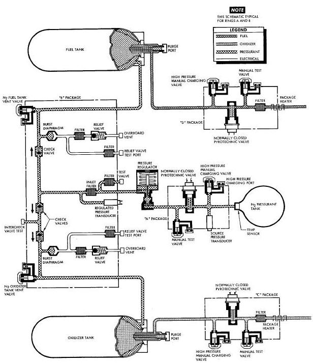
THRUST CHAMBER ASSEMBLY GROUP DIAGRAM
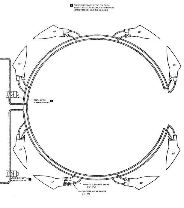
Attitude control (roll, pitch and yaw) is obtained by firing the TCA's in groups. The TCA's are mounted at various points about the RCS section of the spacecraft consistent with the modes of rotational control required. Ring B is thus activated and it begins immediately to execute TSS commands. Ring A is not activated until it is selected. For explanation purposes, the RCS is divided into three groups: the Pressurant, Fuel/0xidizer (or propellant) and Thrust Chamber Assembly (TCA).
PRESSURANT
GROUP
The pressurant group (Figure
Above) consists of a pressurant tank, "A" package, pressure
regulator and "B" package. Valves and test ports are provided at
accessible points to permit servicing, venting, purging and testing.
Filters are provided throughout the system to prevent contamination. The
pressurant is stored and isolated from the remainder of the system by a
normally-closed pyrotechnic
actuated valve, located in the "A" package.
The fuel/oxidizer (propellant) group (Figure Above) consists of expulsion bladder storage tanks, "C" (oxidizer) and "D" (fuel) packages. Valves, ports and test ports are provided at accessible areas to permit servicing, venting, purging and testing. Filters are provided throughout the system to prevent contamination. The propellants are isolated in the storage tanks from the remainder of the system by normally-closed pyrotechnic actuated valves in the "C" and "D" packages. Heaters are installed on the packages to maintain an operating temperature. The propellants used are:
Oxidizer - Nitrogen Tetroxide (N294) conforming
to
Specification MIL - P - 26539A
FUEL - Monomethyl Hydrazine (N2H3CH3) conforming
to Specification MIL - P - 27403
The TCA group (Figure Above) consists of eight 25-pound TCA's used for attitude (roll, pitch and yaw) control of the ATDA. Each TCA is equipped with two solenoid valves which open simultaneously. Heaters, installed on the oxidizer solenoid valves, maintain the oxidizer at an operating temperature.
RCS thruster operation is controlled by signals from the TSS. The RCS (Figure Above) is activated by a signal from the Sequential System. The RCS, in conjunction with the TSS, provides attitude control of the target vehicle in the roll, pitch and yaw axes.
Ring B of the RCS module is selected during pre-launch by a DCS command to provide attitude control and is activated when power is applied at ATDA/Launch Vehicle separation plus eight seconds. Selection of ring A, in the event of a malfunction in ring B, may be accomplished by a DCS command.
The operation of the RCS is described in three groups, Pressurant, Fuel/Oxidizer and Thrust Chamber Assembly.
(Figure
Above) High pressure nitrogen (N2) pressurant is stored at 3000 psi
in the pressurant tank. The tank is serviced through the "A" package
high pressure gas charging port. Pressure from the pressurant tank is
isolated from the remainder of the system by a normally-closed
pyrotechnic actuated valve located in the "A" package. Stored nitrogen
pressure is monitored by the source pressure
transducer located in the "A" package and relayed to the ground station
as instrumentation data. Upon command, the "A" package pyrotechnic
actuated valve is opened and nitrogen flows to the pressure regulator
and "B" package. The "B" package routes the pressure to both propellant
tanks. The regulated pressure is sensed by the pressure transducer ("B"
package) and supplies an output to the Instrumentation System indicating
pressure downstream of the regulator. The check valves prevent backflow
of propellant vapors into the pressurant system. The "B" package has a
safety feature to prevent over pressure of the fuel and oxidizer tank
bladders. Should the system be over pressurized downstream of the
regulator, the pressure would first rupture the burst diaphragms, then
be vented overboard through the relief valves.
Fuel and oxidizer propellants are stored in their respective tanks, and are serviced through the high pressure charging ports in the "C" and "D" packages. The propellants are isolated from the remainder of the system by a normally closed pyrotechnic valves in the "C" and "D" packages. Upon command, the "C" (oxidizer) and "D" (fuel) package pyrotechnic actuated valves are opened and propellants are distributed through their separate tubing manifold system to the thrust chamber inlet solenoid valves.
Two motor operated valves are located in the propellant feed lines, upstream of the TCA's. These valves are opened prior to launch and will remain open throughout the mission. The valves are not connected electrically. Heaters are connected to the output lines of the "C" and "D" packages to prevent freeze-up and are turned on prior to launch by the RCS HRTS switch.
The TCA fuel and oxidizer solenoid valves are controlled by signals from the TSS. In response to the signals, the valves open and propellants are directed through small injector Jets into the thrust chamber. The fuel and oxidizer impinge on one another, where they ignite hypergolically to burn and create thrust. Heaters are connected to each TCA oxidizer solenoid valve to prevent freeze-up and are turned on at launch by the RCS HRTS switch.
The nitrogen (N2) pressurant is stored in a welded, titanium spherical tank. The tank is 7.25 inches in diameter and has an internal volume of 185.0 cubic inches. Nitrogen gas is stored at 3000 psi and held therein by the "A" package pyrotechnic valve until released by a sequential signal. This nitrogen under pressure is used to expel the fuel and oxidizer from their respective tanks.
The "A" package consists of a pressure transducer, isolation valve, filters and two high pressure gas charging valves. The pressure transducer monitors the source pressure and supplies an output to the Instrumentation System, indicating the pressure of the stored gas. The normally closed isolation valve is used to isolate the pressure from the remainder of the system.
The valve is pyrotechnically opened to activate
the system for operation. Two dual seal, high pressure gas charging
valves and ports are provided, on on each side of the isolation
valve. The upstream valve is used for servicing, venting and purging the
pressurant tank, while the downstream valve is used to test downstream
components. Filters are installed to prevent contaminants from
entering the system.
The pressure regulator is conventional, mechanical-pneumatic type. The regulator reduces the source pressure to system operating pressure. An inlet filter reduces any contamination in the gas to an acceptable level.
The "B" package consists of filters, pressure
transducer, three check valves, two burst diaphragms, two relief valves,
regulator output test port, fuel tank vent valve, oxidizer vent valve,
check valve test port and two relief valve test ports. The inlet filter
reduces contamination in the gas to an acceptable level. The relief
valve filters prevent particals from a ruptured burst diaphragm from
entering the relief valves. Test port filters prevent contaminants from
entering the system through the test ports. The pressure transducer
monitors the regulated pressure and supplies an output to the
Instrumentation System. Check valves prevent backflow of fuel or
oxidizer into the pressurant system. The burst diaphragms are safety
devices that rapture when the pressure reaches the
design failure pressure, thus, prevents imposing excessive pressure on
the propellant bladders.
The two relief valves are conventioan mechanical-pneumatic type with the pre-set opening pressure. In the event of burst diaphragm rupture, the relief valve opens to vent excess pressure overboard. The valve reseats when a safe level is reached. This prevents venting the entire gas source. Manual valves and ports are provided to vent, purge and test the regulated system.
The fuel tank is a welded, titanium cylindrical
tank which contains an internal bladder and purge port. The tank is 5.10
inches outside diameter, 30.7 inches in length and has a fluid volume
capacity of 546.0 cubic inches. The nitrogen pressurant is imposed on
the exterior of the bladder to expel fuel through the "D" package to the
TCA solenoid valves. The purge port is provided to purge and
vent the fuel tank bladder.
The oxidizer tank is a welded, titanium
cylindrical tank which contains a bladder and purge port. The tank is
5.10 inches outside diameter, 25.2 inches in length and has a fluid
volume capacity of 439.0 cubic inches. The bladder is a double layered
Teflon, positive expulsion type. The nitrogen pressurant is imposed on
the exterior of the bladder to expel the oxidizer through the "C"
package to the
TCA solenoid valve. The purge port is provided for purging and venting
the oxidizer tank bladder.
The "C" and "D" packages are identical in operation and are located downstream of the tanks of their respective system. Each package consists of filters, an isolation valve, propellant charging valve and test valve. The in llne filter reduces practical contamination to an acceptable level. The valve filters prevent contaminants from entering the system. The normally closed isolation valve is used to isolate propellants from the remainder of the system until ready for use. The isolation valve is opened pyrotechnically to activate the system. The propellant charging valve is located upstream of the isolation valve and is used for sel_iclng and venting the system. A test valve Is used to test the system, downstream of the isolation valve.
PROPELLANT SUPPLY SHUTOFF VALVES
Motor operated propellant supply shutoff valves are located downstream of the "C" and "D" packages. The valves are opened during pre-launch and are not connected electrically.
Each TCA consists of two propellant valves,
injection system, calibrated orifices, combustion chamber and expansion
nozzle. The fuel and oxidizer solenoid valves are the normally-closed
quick acting type, which open simultaneously upon command. The action
permits fuel and oxidizer flow into the injector system. The injectors
use precise Jets to impinge fuel and oxidizer streams on one another for
controlled mixing and combustion. The calibrated orifices are fixed
devices used to control propellant flow. Hypergolic ignition occurs in
the combustion chamber. The combustion chamber and expansion nozzle are
lined with ablative materials and insulation to absorb and dissipate
heat and control external wall temperature. TCA's are installed within
the RCS module mold line, with the nozzles terminating flush with
the outer mold llne. TCA's are located at fixed points on the RCS module
in a location suitable for attitude control.
Thermostatically controlled electric heaters, located at various points in the system, are used to prevent propellant from freezing.
AGE - Aerospace Ground Equipment (AGE)
ATDA - Augmented Target Docking Adapter (ATDA)
BRD - Biased Rate Damping (BRD)
DCS - Digital Commend System (DCS)
FLSC - Flexible Linear Shaped Charge (FLSC)
PETN - Penta Erythritol Tetra Nitrate (PETN)
PCM - Pulse Code Modulated (PCM)
RCS - Reaction Control System (RCS)
TBS - Target Stabilization System (TBS)
TCA - Thrust Chamber Assembly (TCA)
TDA - Target Docking Adapter (TDA)
VECO - Vernier Engine Cut-Off (VECO)