|


Systems
AUGMENTED TARGET DOCKING ADAPTER (Agena)
Cabin
Command Link
Cooling
Communications
Docking
Electrical
Environment Control
Extra-Vehicular Activity
Horizontal Sensor System
Instrumentation
Landing
Navigation
Propulsion
PYROTECHNICS and RETRO ROCKET SYSTEM
Rendezvous Radar
Sequence
Target Docking Adapter
Time Reference System
MAJOR STRUCTURAL ASSEMBLIES
Interior Arrangement (Typical) Diagram
Spacecraft Genera Nomenclature Diagram
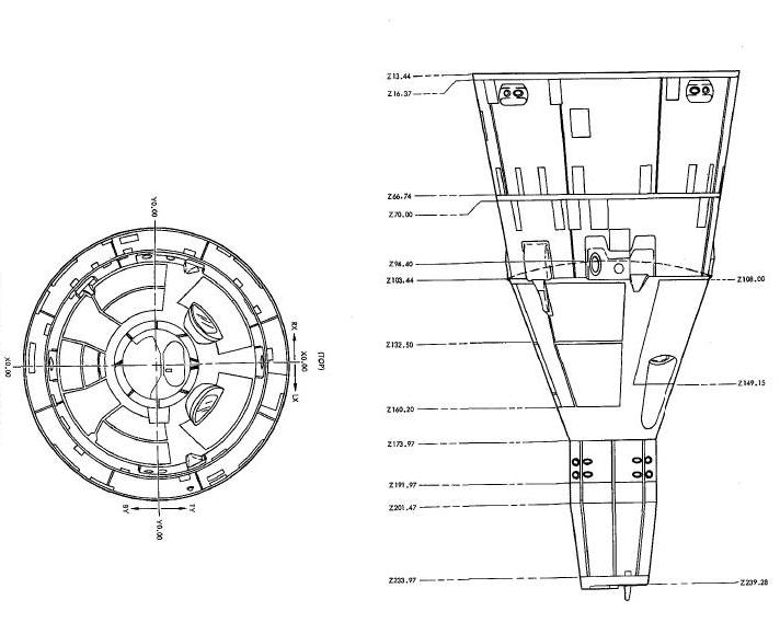
Re-entry Module Structure Diagram
RE-ENTRY CONTROL SYSTEM SECTION
Access Doors Spacecraft 5,6,8 and Up
Access Doors Spacecraft 5, 6, 8 and Up
Spacecraft Ingress/Egress Hatches Display
Re-Entry Module-Adapter Retaining Strap Diagram
SPACECRAFT/LAUNCH VEHICLE MATING
Spacecraft/Launch Vehicle Mating Ring Diagram
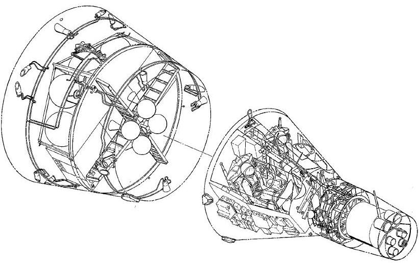
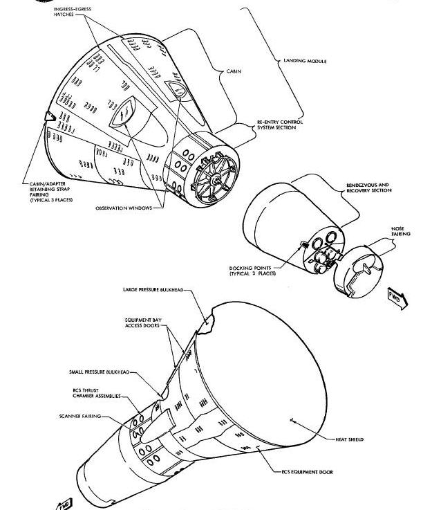
The Gemini Spacecraft is basically of a conical configuration (Figure Below) consisting of a re-entry module and an adapter as the two major assemblies. Spacecraft construction is semimonocoque, utilizing titanium for the primary structure. It is designed to shield the cabin pressure vessel from excessive temperature variations, noise and meteorite penetration (This Figure). See This Figures and This Figure for spacecraft orientation.
Interior Arrangement (Typical) Diagram
Spacecraft Genera Nomenclature Diagram
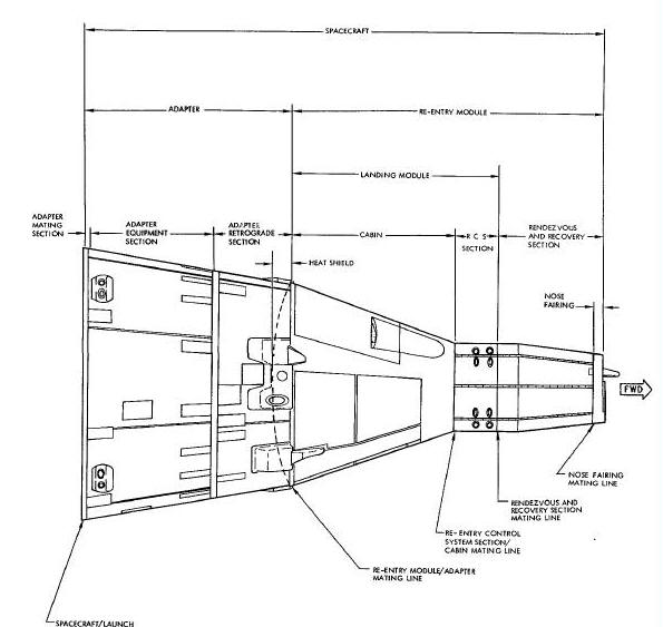
The re-entry module (Figure Below) is separated into three primary sections which include the Rendezvous and Recovery section (R and R), Re-entry Control System section (RCS) and the cabin section. Also incorporated in the re-entry module is the heat shield which is attached to the cabin, and a nose fairing which is attached to the forward end of the R and R section. The nose fairing is ejected during launch.
Re-entry Module Structure Diagram
RENDEZVOUS AND RECOVERY SECTION
The (R and R) section (Figure
Above), the forward section of the spacecraft, is semiconical in
shape and is attached to the Re-entry Control System section with
twenty-four bolts. Incorporated in this joint is a pyrotechnic device
which severs all bolts causing the rendezvous section to separate from
the RCS section on signal for parachute deployment. A drogue parachute
will assist in the removal of this section. The R and R section utilizes
rings, stringers and bulkheads of titanium for its primary structure.
The external surface is composed of beryllium shingles, except for the
nose fairing. The nose fairing is composed of fiberglass reinforced
plastic laminate.
RE-ENTRY CONTROL SYSTEM SECTION
The RCS section is located between, and mated to, the R and R and cabin sections of the spacecraft (Figure Above). This section is cylindrical in shape and is constructed of an inner titanium alloy cylinder, eight stringers, two rings and eight beryllium shingles for its outer skin. The RCS section is designed to house the fuel and oxidizer tanks, valves, tube assemblies, and thrust chamber assemblies for the RCS. A parachute adapter assembly is installed on the forward face of the RCS section for attachment of the main parachute.
The cabin (Figure Above), similar in shape to a truncated cone, is mated to the RCS section and the adapter. The cabin has an internal pressure vessel (Figure Below) shaped to provide am adequate crew station with a proper water flotation attitude. The shape of the pressure vessel also allows space between it and the outer conical shell for the installation of equipment.
The basic cabin structure consists of a fusion welded titanium frame assembly to which the side panels, small and large pressure bulkheads and hatch sill are seam welded. The side panels, small and large pressure bulkheads are of double skin construction amd reinforced by stiffeners spot-welded in place. Two hatches are hinged to the hatch sill for pilot ingress and egress. For heat protection, the outer comical surface is covered with Rene' 41 shingles and an ablative heat shield is attached to the large end of the cabin section.
A spring loaded hoist loop, located near the heat shield between the
hatch openings, is erected after landing to facilitate engagement of a
hoisting hook for spacecraft retrieval.
The equipment bays are located outside the cabin pressure vessel (Figure Below). Two bays are located outboard of the side panels and one bay beneath the pressure vessel floor. The bays are structurally designed for mounting of the equipment.
Access Doors Spacecraft 5,6,8 and Up
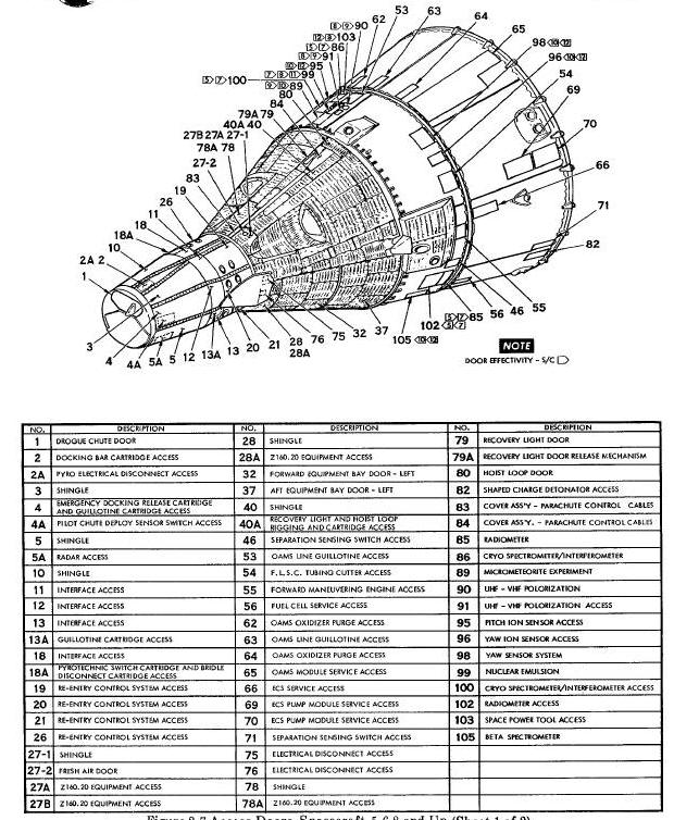
Access Doors Spacecraft 5, 6, 8 and Up
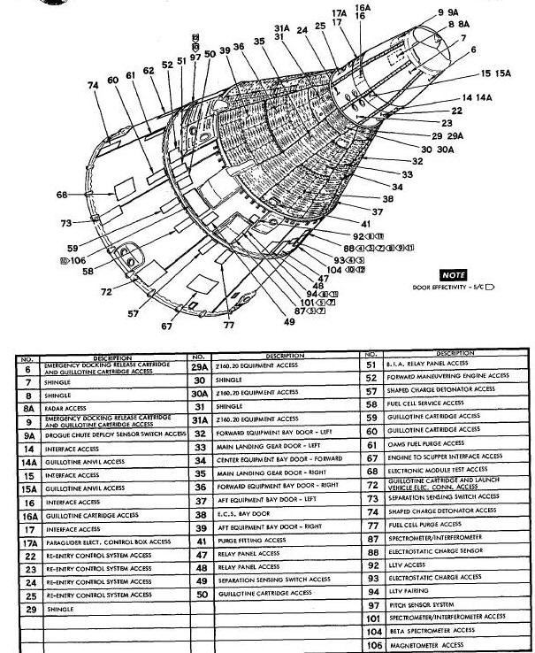
To enclose the side equipment bays, two structural doors are provided on each side of the cabin (Figure Above). These doors provide access to the components installed in the equipment bays. The main landing gear bays, located below the left and right equipment bays, are each enclosed by one door. The landing gear is not installed but fittings are provided for the attachment of the gear for future spacecraft. 0m the bottom of the cabin, between the landing gear doors, two additional doors are installed. The forward door allows access to the lower equipment compartment and the aft door provides access to the Environmental Control System compartment which is a portion of the pressure vessel.
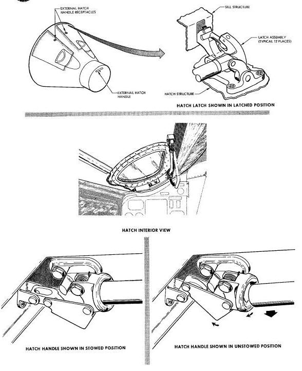
Two large structural hatches (Figure
Below) are incorporated for sealing the cabin ingress or egress
openings. The hatches are symmetrically spaced on the top side of the
cabin section. Each hatch is manually operated by means of a handle and
mechanical latching mechanism. Each is hinged on the outboard side. In
an emergency, the hatches are opened in a three sequence operation
employing pyrotechnic actuators. When initiated, the actuators
simultaneously unlock and open the mechanical latches, open the hatches
and supply hot gases to ignite the ejection seat rocket catapults. An
external hatch linkage fitting is incorporated to allow a recovery hatch
handle to be inserted for opening the hatches from the outside. The
recovery hatch handle is stowed on the main parachute adapter assembly
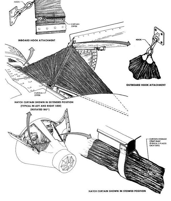
located on the forward face of the RCS section. A hatch curtain (This
Figure) is stowed along the hinge of each hatch. After water
landing, when the hatches are open, the curtains are installed to help
prevent water from entering
the cabin.
Spacecraft Ingress/Egress Hatches Display
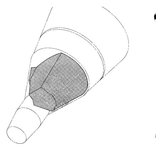
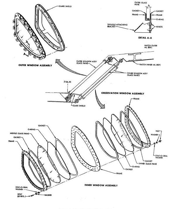
Each of the ingress/egress hatches incorporates a visual observation window (Figure Below). Each window consists of an inner and outer glass assembly. The outer assembly is a single flat paine and the inner panel assembly consists of two flat panes. The panes consist of Vycor (96% silica). The panes in the right window are optically ground for better resolution. Each surface of each pane, with the exception of the outer surface of the outer panel is coated to lessen reflection and glare from cabin lights and to aid in impeding ultraviolet radiation into the cabin compartment.
The heat shield is a dish-shaped structure composed of silicone elastomer filled, phenolic impregnated, fiberglass honeycomb. It is an ablative device, 90 inches in diameter with a spherical radius of 144 inches. The shield is designed to protect the re-entry module from extreme thermal conditions during re-entry into the atmosphere. The device is attached to the large diameter end of the cabin structure by 1/4 inch bolts.
The external surface of the cabin is made up of beaded shingles of
Rene' 41. The R and R and RCS section surfaces are made up of umbeaded
shingles of beryllium. The shingles protect the re-entry module
structure from excessive heat and provide additional rigidity for the
cabin. The shingles are black on the outer surface to control thermal
radiation. The inner surface of the beryllium shingles are coated with
gold to provide a low emissivity surface.
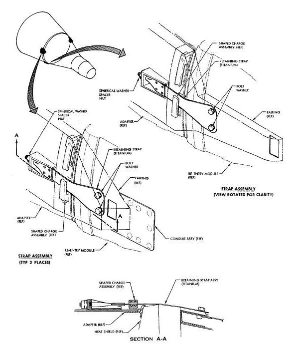
The adapter functions to mate the spacecraft to the launch vehicle, to provide for mounting equipment and retrograde rockets , and to serve as a radiator for the spacecraft coolant system. The adapter (Figure Above) is a truncated cone-shape, simimonocoque structure consisting of circumferential aluminum rings, extruded magnesium alloy stringers, and magnesium skin. The extruded stringers are designed in a bulb-tee shape to provide a flow path for the liquid coolant which transfers heat to the adapter skin for radiation to space. The outer surface of the skin is coated with white ceramic type paint and the inner surface is covered with aluminum foil. The inner adapter surfaces of spacecraft 9 through 12 are gold plated. The forward end of the adapter is coupled to the aft end of the re-entry module by utilizing three titanium tension straps (Figure Below).
Re-Entry Module-Adapter Retaining Strap Diagram
The retrograde section, the smaller end of the adapter, provides for installation of four retrograde rockets and six Orbital Attitude Maneuvering System thrust chamber assemblies. To provide for the installation of the retrograde rockets, the retrograde section employs an aluminum I beam support assembly. The I beams are assembled in the form of a cruciform with one retrograde rocket mounted in each quadrant.
The equipment section is the larger diameter end of the adapter. The section provides hard points for the attachment of structural modules for the OAMS tanks, Environmental Control System primary oxygen supply, fuel cell (batteries on spacecraft 6), coolant, electrical and electronic components, Extra Vehicular Activity (EVA) equipment on spacecraft 9 through 12, and Rendezvous Evaluation Pod on spacecraft 5 only. A honeycomb blast shield is provided above the modules to shield the equipment section and booster dome from excessive heat during retrograde rocket firing under abort conditions. Ten OAMS thrust chamber assemblies are mounted on the large diameter end of the equipment section. A gold deposited fiberglass temperature control cover protects the equipment fred solar radiation through the open end of the adapter after separation from the launch vehicle.
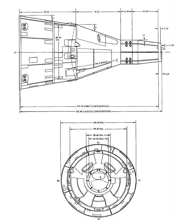
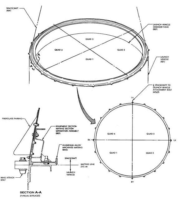
SPACECRAFT/LAUNCH VEHICLE MATING
The spacecraft is mated to the Titan II Launch Vehicle with a machined aluminum alloy ring (Figure Below). This ring, 120 inches in diameter, mates with the launch vehicle mating ring. Twenty bolts secure the rings together. To provide for alignment, the launch vehicle incorporates one steel 3/26 inch diameter alignment pin located at TY and four index marks. To separate the spacecraft from the launch vehicle, a pyrotechnic charge is fired, severing the adapter section approximately 1½ inches above the launch vehicle/spacecraft mating point.
Spacecraft/Launch Vehicle Mating Ring
E
EVA - Extra Vehicular Activity (EVA)
R
RCS - Re-entry Control System section (RCS)
(R and R) - Rendezvous and Recovery section (R and R)