
COMMAND LINK
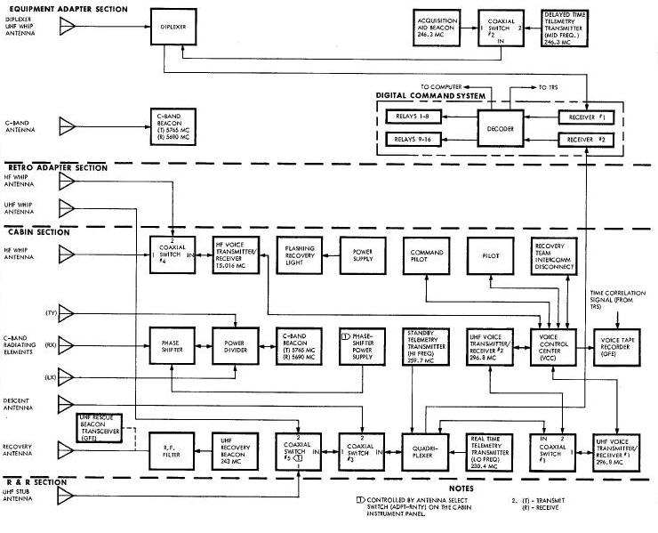
Command Link System Block Diagram
COMMAND FUNCTION LIST AGENA TARGET VEHICLE
SYSTEM DESCRIPTIONSYSTEM DESCRIPTION
The Command Link System (Figure Below) is incorporated into the Gemini Spacecraft to allow the spacecraft pilot to control the target vehicle. Command link control is used as a means of positioning the target vehicle in the desired attitude and orbital path, of turning acquisition and approach lights on or off, and for controlling Communications and Instrumentation Systems required for ground monitoring.
Using the radar rf transmission prior to docking and a hardline umbilical after docking, the command link is capable of transmitting a possible 128 command messages (Figure below).
Command Link System Block Diagram
Commands presently allocated and a corresponding three digit number for each of the commands are listed in Table Below.
| COMMAND FUNCTION LIST AGENA TARGET VEHICLE | ||
| Spacecraft Command Number | Real Time Command | COMMAND TITLE |
| 001 | 0000001 | C-Band Beacon On |
| 010 | 0000010 | S-Band Beacon On |
| 011 | 0000011 | Modulation Bus SelelctNormal |
| 020 | 0000100 | Modulation Bus Selelct Reverse |
| 021 | 0000101 | Telemetry On |
| 030 | 0000110 | Telemetry Off |
| 031 | 0000111 | Stored Data Readout |
| 041 | 0001001 | Record Data |
| 050 | 0001010 | C and S-Band Beacons Off |
| 060 | 0001100 | Reset Timer Reset |
| 061 | 0001101 | Time Word Reset |
| 070 | 0001110 | L-Band Beacon Off |
| 071 | 0001111 | L-Band Beacon On |
| 140 | 0011000 | Approach Lights Off |
| 141 | 0011001 | Approach Lights On |
| 151 | 0011011 | Extend Boom Antenna |
| 160 | 0011100 | Antenna Transfer, Ascent |
| 161 | 0011101 | Antenna Transfer, Orbit |
| 200 | 0100000 | Agena Status Display Off |
| 201 | 0100001 | Agena Status Display On Bright |
| 211 | 0100011 | Agena Status Display On Dim |
| 220 | 0100100 | Adapter Unrigidize |
| 221 | 0100101 | Adapter Ridlgize |
| 240 | 0101000 | Stored Program Commands Disable |
| 241 | 0101001 | Stored Program Commands Enable |
| 250 | 0101010 | Acquisition Lights Off |
| 251 | 0101011 | Acquisition Lights On |
| 260 | 0101100 | Dipole Select |
| 270 | 0101110 | Spiral Select |
| 271 | 0101111 | Power Relay Reset |
| 300 | 0110000 | Horizon Sensor Off |
| 301 | 0110001 | Horizon Sensor On |
| 310 | 0110010 | Roll Horizon Sensor to Yaw, Inertial Reference Package On |
| 311 | 0110011 | Pitch Horizon
Sensor to Yaw 3 Inertial Reference Package On |
| 320 | 0110100 | Horizon Sensor to Yaw Out of Phase |
| 321 | 0110101 | Horizon Sensor to Yaw in Phase |
| 340 | 0111000 | Velocity Meter Interrogate |
| 341 | 0111001 | Gyrocompass On |
| 350 | 0111010 | Geocentric Rate Off |
| 351 | 0111011 | Geocentric Pate On |
| 360 | 0111100 | Geocentric Rate Reverse |
| 361 | 0111101 | Geocentric Rate Normal |
| 370 | 0111110 | Attitude Control System Pressure Low |
| 371 | 0111111 | Attitude Control System Pressure High |
| 400 | 1000000 | Attitude Control System Off |
| 401 | 1000001 | Attitude Control System On |
| 410 | 1000010 | Pitch/Yaw Minus |
| 411 | 1000011 | Pitch/Yaw Plus |
| 420 | 1000100 | Pitch/Yaw Low Rate |
| 421 | 1000101 | Pitch/Yaw High Rate |
| 430 | 1000110 | Pitch Rate Off |
| 431 | 1000111 | Pitch Rate On |
| 440 | 1001000 | Yaw Off |
| 441 | 1001001 | Yaw On |
| 450 | 1001010 | Attitude Control System Deadband Narrow |
| 451 | 1001011 | Attitude Control System Deadband Wide |
| 460 | 1001100 | Attitude Control System Gain Low |
| 470 | 1001110 | Attitude Control System Gain High - Undocked |
| 471 | 1001111 | Attitude Control System Gain High - Docked |
| 500 | 1010000 | Primary Propulsion System Cutoff |
| 501 | 1010001 | Primary Propulsion System Start |
| 520 | 1010100 | Velocity Meter Disable |
| 521 | 1010101 | Velocity Meter Enable |
| 530 | 1010110 | Velocity Meter Load 0 |
| 531 | 1010111 | Velocity Meter Load 1 |
| 540 | 1011000 | Velocity Meter to Mode IV Off |
| 541 | 1011001 | Velocity Meter to Mode IV On |
| 550 | 1011010 | Secondary Propulsion System Thrust Cutout |
| 551 | 1011011 | Secondary Propulsion System 16 Thrust Initiate |
| 560 | 1011100 | Secondary Propulsion System 200 Thrust Initiate |
| 561 | 1011101 | Secondary Propulsion System Ready |
| 570 | 1011110 | Hydraulics Gain - Undocked |
| 571 | 1011111 | Hydraulics Gain - Docked |
Prior to docking the command link may be used any time that the rendezvous radar aboard the spacecraft is locked onto the radar transponder located in docking adapter of the target vehicle. The desired command message is inserted, by the pilot, into the encoder controller, located below and slightly aft of the right switch/circuit breaker panel. The message is then transmitted by pulse position modulation of the radar transmission through the transponder to the target vehicle programmer.
After docking, the command link messages are routed through the hardline umbilical. The method by which the pilot inserts the desired message remains unchanged. The command link also provides the pilot with the capability to unlatch from the target vehicle at the completion of the mission.
The Command Link System is energized by placing the ENCDR circuit breaker in the ON position. The ENCDR circuit breaker is located on the right switch/circuit breaker panel. The command link may now be used for the transmission of messages.
To initiate a commnd the Gemini pilot selects a
command from a list provided.
Inserts the corresponding three digit number into the encoder
controller. For example; Target Docking Adapter Acquisition Lights On
command number is
251. To transmit this message the Gemini pilot adjusts the encoder
controller
to the following positions: the outer octal dial is turned to 2, the
inner
octal dial is turned to 5, and the binary switch (XMIT) is positioned to
1 and
held until the message cycle described in this section is completed. The
only
effect of the command link message transmission on the rendezvous radar
is the changing of the radar pulse repetition frequency. During the
message transmission the radar is switched from the internal generated
pulse to the more stable Time Reference System generated 256 pulses per
Second.
The encoder controller output is a seven binary digit (bit) binary word, three binary bits indicating each octal number and one binary bit corresponding to the XMIT switch. The command message is added to the vehicle address, consisting of two binaryblts, and the system address, consisting of three binary blts. The vehicle address used is the two binary numbers 1 1, the system address is 1 0 1. It is therefore seen that the complete command function word is as follows:
| Vehical Address | System Address | Command | |
| 2 | 5 | ||
| 11 | 101 | 010 | 010 |
The positioning of the XMIT switch to either the I or the 0 position also initiates a one time transmission of the command.
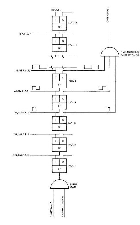
The command llnk data transmission is accomplished in the following manner. The Time Reference System provides two trigger pulses to the encoder, both having a repetition rate of 256 pulses per second. One pulse will be referred to as occurring at Time Zero (T0) and the other at time zero plus 15.2 microseconds (T0 + 15.2). At the time the ENCDR ON circuit breaker is turned ON the radar commences being pulsed by the T0 pulse from the Time Reference System. The transmit command, initiated by the XMIT switch, causes the information bit to be taken, one at a time commencing with the vehicle address, and further encoded into five binary sub-bits. The encoder affects pulse position modulation of the radar interrogate transmission by allowing the T0 or T0 + 15.2 pulse to trigger the radar, indicating a 0 or a 1 respectively.
The interrogate transmission, at the repetition rate of 256 pulses per second, is received at the radar transponder. The transponder receiver video signal is applied to the sub-blt detector. The sub-bit detector contains an oscillator which is synchronized with the received interrogate 0 pulse. The oscillator provides two gates, one which occurs in synchronism with the T0 pulse and another with the T0 + 15.2 pulse. The coincidence of the received pulse with one of the above gates results in the identification of the pulse modulation. A decoded 0 generates a 25 microsecond pulse across the message complement output and a decoded I generates a 25 microsecond pulse across the message output. These pulses are provided to the programmer.
The programmer converts the 60 sub-bits back into the 12 information bits. The programmer verifies that the sub-bit code is correct, that the vehicle and system address is correct, and that an acceptable message was received. If the aforementioned requirements are met the programmer will provide a message acceptance pulse to the transponder. The message acceptance pulse causes three consecutive transmissions from the transponder to shift from the normal six microsecond pulse width to ten microseconds. The radar detects the additional pulse width and causes the Message Accept (MSG ACPT) light, located on the encoder controller to illuminate for a period of 2.5 seconds.
The illumination of the MSG ACPT light indicates to the pilot that an acceptable message has been received by the programmer. At this time the pilot may release the XMIT switch.
The purpose of the sub-bit detector (Figure below) is the conversion of the radar transmitted pulse modulation to a pulse form indicative of the 0 and 1 subbit code. The sub-bit detector is also used to control the sending of the message acceptance pulse to the Gemini Spacecraft.
Prior to lock-up of the Command Link System the sub-bit detector is held in a standby state by the incorporation of a pre-acquisition loop. The variable frequency oscillator, driven at a rate of 253 cycles per second, is insensitive to lesser frequencies. The modulated radar transmission is applied to the detector in two forms, the transponder receiver video pulse and a pulse in synchronism with the leading edge of the video. The sync pulse iS applied to the oscillator thereby causing the frequency to increase to 256 cycles per second and synchronizing the early and late gates to the incoming video pulse.
The early gate and late gate, initiated by the
variable frequency oscillator, are for tracking the interrogate pulse
repetition frequency and detecting the transmission of the pulse
corresponding to the binary sub-bit 0. The two gates are each 0-75
microseconds in width and are so related that the trailing edge of the
early gate abuts on the leading edge of the late gate. The combined
width of the gates is slightly more than the video pulse. The video
pulse is to be centered equally between the two gates; any deviation
frsm this condition will result in an appropriate control voltage
applied to the variable frequency oscillator.
The radar modulation is determined by observing the presence of the radar transmission in either the combined early and late gate or ithe one gate, a 1.5 microsecond gate occurring 15.2 microseconds from the leading edge of the early gate. The continuous transmission of the sub-blt 0 enables the synchronization of the variable frequency oscillator. A slow frequency control loop provides memory so that a command message may be sent and the oscillator iwill maintain the correct 0 and 1 time relationship.
The sub-bit detector provides a 25 microsecond pulse over the message line to indicate a 1 and a 25 microsecond pulse over the message complement line to indicate a 0. These pulses, along, with a sync pulse which occurs for either 0 or 1, are then coupled to the computer.
The command link encoder (Figure Below) is provided to link the commands entered into the encoder controller, by the Gemini Spacecraft pilot, to the target vehicle via two completely separate communication channels. The channel initially used is the rf link using the rendezvous radar transmission as a carrier, the link used after the docking maneuver is the hardline umbilical.
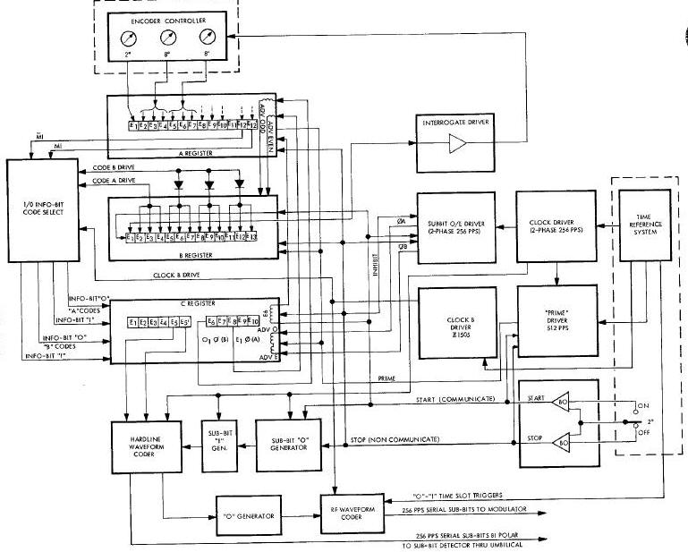
The command link message is comprised of 12 binary information bits, a vehicle address, a system address, and a command function word. The initial portion of the message, the vehicle address consisting of two information bits and the system address consisting of three information bits, are fixed in content. The command function word is made up of seven information bits, thereby allowing 128 possible commands.
The task of entering a command by manipulating seven switches, each
having binary states, is undesirable from a human factors standpoint. An
octal form of coding, entered by two octal switches and a binary switch,
is selected for use by the spacecraft pilots. The pilot is provided with
a list showing the individual commands and the corresponding three digit
number. The message is entered into the encoder controller located below
and slightly aft of the right switch/circuit breaker panel. The encoder
switches establish a unique current routing path through a twelve bit
multiaperture magnetic core shift register in the encoder for each of
the 128 possible commands. The setting iof the encoding switches, which
represent a particular command function word, are interrogated and
encoded
into the infobit shift register as magnetization states of magnetic
cores by means of the interrogate current pulse generated by the encoder
subsequent to actuation of the ET switch.
The twelve information bits are shifted sequentially in information
bit message (1) and message complement (0) form from the information bit
shift register and further encoded, one at a time, into another shift
register in accordance with pseudo-random sub-bit code. Each is encoded
into five sub-bits which are shifted sequentially in sub-bit message (1)
and message complement (0) form at a 256 pulses per second rate to the
hardline waveform coder. The complete message format, as a consequence
of the encoding process, is a serial group of 60 sub-bits. For the
hardline link the binary coded message is presented to the sub-bit
detector, located in the transponder, as bipolor return-to-zero signals.
For the rf link, the sub-bit message and message complement signals are
pulse
position modulated by the rf waveform coder in the encoder and are
connected to the grid modulator of the radar. The method of pulse
position modulation used will cause a normal radar pulse, indicative of
the sub-bit message 0, to be transmitted in the first defined time slot
while a sub-bit message I will cause transmission of the rf pulse
delayed 15.2 microseconds from the normal, or 0
position.