
DOCKING
RENDEZVOUS AND RECOVERY SECTION
RIGIDIZING AND UNRIGIDIZING SEQUENCE
Docking System Operation Diagram
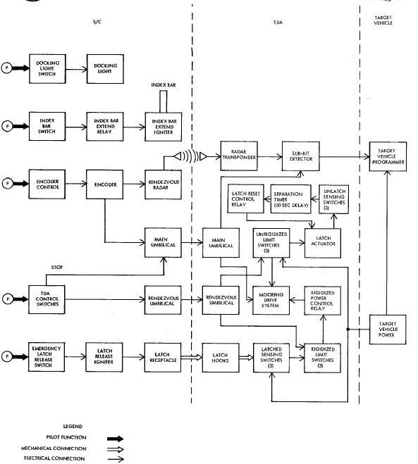
Docking System Electrical Block Diagram
#MOORING LATCHC COVER ASSEMBLIES
RADAR SYSTEM AND PYROTECHNIC DEVICES
TARGET VEHICLE STATUS DISPLAY PANEL
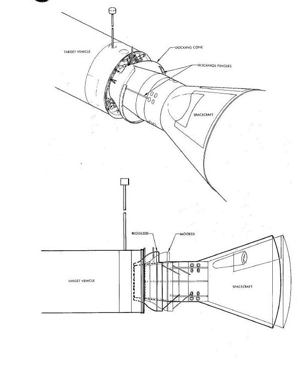
The Docking System (Figure Below) is used on spacecraft 8 through 12 and utilizes two major assemblies: the spacecraft Rendezvous and Recovery (R & R) section and the Target Docking Adapter (TDA) assembly. These assemblies permit the spacecraft to mate with the target vehicle during orbital flight. The TDA assembly may be mounted on either the Agena Target Vehicle (ATV) or the Augmented Target Docking Adapter (ATDA). The docking cone receives the spacecraft R & R section during docking. Electrical mechanical devices in the spacecraft and the docking adapter control the docking operations automatically or as directed by the pilots or the ground control stations. For convenience, these major assemblies are considered separately. In this section, details of the R & R section of the spacecraft, approach and mooring, rigidizing and unrigidizing to the target vehicle are presented. Details of the TDA are presented in the Target Docking Adapter section.
RENDEZVOUS AND RECOVERY SECTION
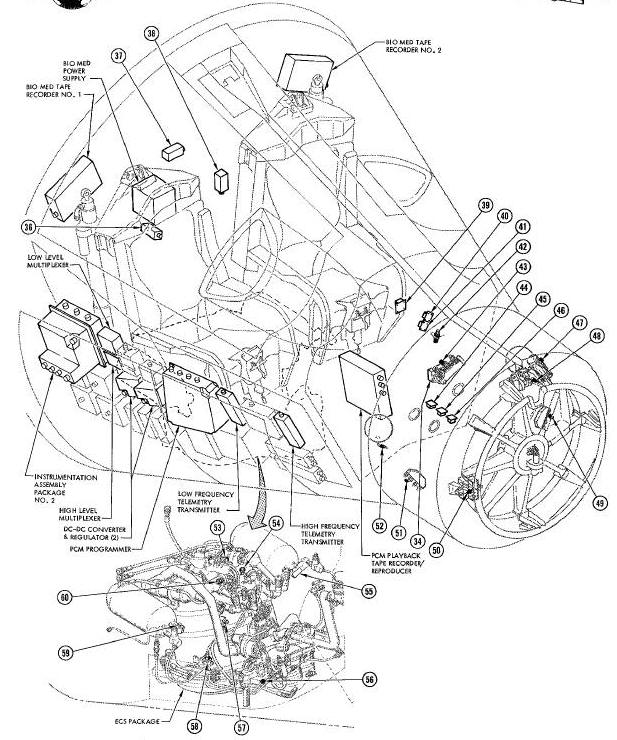
The R & R section of the spacecraft (Figure Below) contains the following Docking System units: the support structure, a nose fairing, an index bar, 3 mooring latch receptacles, 3 latch-receptacle covers, an umbilical connector (receptacle), two rendezvous umbilical connectors (pads), pyrotechnic cable cutters and ejection devices. Other components of the R & R section are not concerned with docking. The main structure is secured to the spacecraft and serves as a mounting structure for other units.
The nose fairing is rigidly but temporarily
fastened to the forward end of the R & R section. The fairing is
Jettisoned at spacecraft separation from the launch vehicle. A
pyrotechnic igniter severs a shear pin and swings the fairing clear of
the spacecraft. The docking latch receptacles are exposed as the fairing
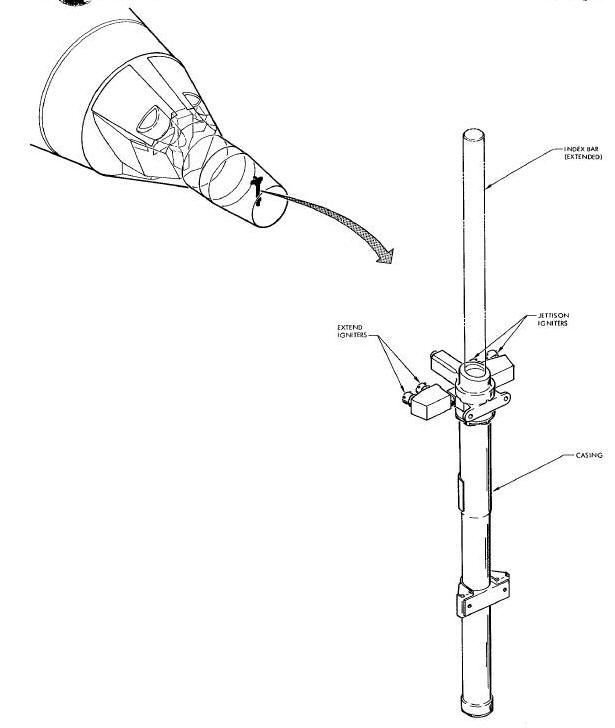
is Jettisoned. The index bar is so located that it coincides with the
slot in the
docking cone when properly aligned. The bar is extended pyrotechnically
by the pilots and remains extended until Jettisoned at retrograde
adapter separation. The pilots use the bar to align the spacecraft with
the docking cone. The pilots use another set of igniters to Jettison the
bar. The bar can neither be extended or Jettisoned prior to nose fairing
Jettison.
The three latch receptacles are equally spaced
around the forward perimeter of the R & R section. The lower latch
serves as a pivot for the nose fairing when it is Jettisoned. The
exposed receptacles latch with the mooring latch hooks on the docking
cone as the two units come in contact during the docking maneuver. The
latch receptacles will remain latched until unlatched automatically by
the
separation sequence. The latch receptacles are Jettisoned Just before
re-entry or during an emergency. The cavities left by the Jettisoned
receptacles are covered by pyrotechnically released covers before
re-entry. Relays prevent these operations until after the nose fairing
has been Jettisoned.
The Rendezvous Radar is located in the front part of the R & R section and consists of the transmitter-receiver unit plus 3 receiving antennas and one transmitting antenna. The radar (and encoder) are used to control the target vehicle before docking. The pilots can initiate a number of encoded commands via the Command Link System to accomplish this.
The rendezvous umbilical pads mate with the rendezvous umbilical lever assemblies on the docking cone, at the same time the latch hooks engage the latch receptacles. The main umbilical receptacle mates with its umbilical plug during the rigidizing sequence of the docking maneuver. The umbilical connection provides direct hardline control of the target vehicle. This control includes simple switching and encoded commands.
Pyrotechnic igniters are used to extend the index bar, Jettison the index bar and the mooring latches, Jettison the nose fairing and release the latch covers. The pyrotechnic igniters are fired electrically from the crew station.
The approach and mooring sequence is initiated by a ground station command to the target vehicle. Using the Digital Command System, the ground station will turn on electrical power and radar transponder circuits and extend the dipole antenna on the TDA. This allows the pilots of the spacecraft to make contact with the target vehicle using the Rendezvous Radar System.
The pilots will begin tracking and control the target vehicle at approximately 100 nautical miles separation. When the separation is about 20 nautical miles, the pilots can use the Command Link System to unrigidize the docking cone and turn on the acquisition Lights. At about 500 feet separation, the pilots use the Command Link to turn on the approach lights and status display panel lights. The pilots will extend the index bar pyrotechnically and decrease the spacecraft closing rate to 0.7 feet per second. Later, the pilots turn on the spacecraft docking light. As the target vehicle is approached, the pilots use spacecraft closing rate to 0.7 feet per second. Later, the pilots turn on the suacecraft docking light. As the target vehicle is approached, the pilots use spacecraft thrusters and the index bar to align the spacecraft with the docking cone.
When proper aliment is achieved the pilots begin
the mooring sequence. The mooring sequence is completed when the
spacecraft is firmly connected to the docking cone in the unrigidized
position. First contact between the R & R section and the docking cone
is with three electrical discharge fingers protruding from the docking
cone. These discharge fingers are so wired that any static charge
between the spacecraft and the target vehicle will be dissipated at a
controlled rate. As the pilots thrust the R & R section further into the
docking cone the spring loaded mooring latch hooks are pushed aside,
then drop behind the latch receptacles to create the latched condition.
At the same time the two rendezvous umbilical connectors are mated and
provide direct hardline control to the TDA
mooring drive system.
RIGIDIZING AND UNRIGIDIZING SEQUENCE
The rigidize sequence and the unrigidize sequence are automatic ones when they are initiated. The rigidize sequence is initiated when the spacecraft R & R section contacts the latch hooks, pushes them aside and then allows the hooks to lock on to the latch receptacles. Latch engagement is sensed by three limit switches, one at each latch position. The sensing switches route target vehicle electrical power through the rigidize limit switches to the rigidized power control relay. The relay energizes, connecting target vehicle electrical power to the mooring drive system motor. When the system is rigidized, the rigidized limit switches open, de-energizing the rigidized power control relay and stopping the motor. The main umbilical plug is extended during the rigidize sequence.
The unrigidize sequence is automatic once it is
initiated by either ground command or by the pilots. When the mooring
drive system is unrigidized, the unrigidized limit switches route target
vehicle electrical power to the latch actuator. When the mechanism is
unlatched, the unlatch sensing switch routes target vehicle electrical
power to the separation timer. The timer, after a 30-second delay,
applies power to the reset side of the latch actuator through the latch
reset control relay and the latch reset relay. The latch hooks are reset
so that the docking maneuver can be repeated. Normally the cone does not
rigidize after reset of the latch hooks but if the pilot does not back
away within the 30-second delay before reset, the cone will rigidize.
The unrigidize sequence would then
have to be repeated.
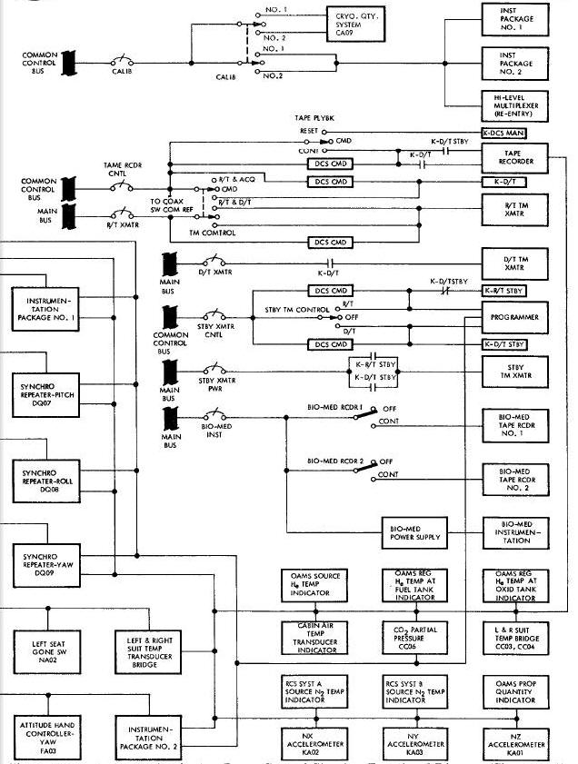
The Docking System operation (Figure Below) illustrates the sequence in witch docking is accomplished. Control of the Docking System is primarily electrical but pyrotechnic devices and mechanical sensing switches are integrated into the system. The Docking System electrical block diagram (Figure Below) links together various assemblies used in the docking operation. The electrical system provides the capability for the pilots or ground station to control the docking operation. The operation of the Docking System consists of three basic functions: (1) Docking sequence, (2) Maneuvering sequence, (3) Separation sequence.
Docking System Operation Diagram
Docking System Electrical Block Diagram
The docking sequence consists of approach, mooring, rigidizing and main umbilical connection.
The pilots in coordination with the ground station control the Docking System (Figure Above).
During the approach phase, the Digital Command
System is used to switch on the target vehicle command circuits, the
docking adapter radar transponder and to extend the docking adapter
dipole antenna boom. With this accomplished, the pilots and the ground
stations can control other docking adapter/target vehicle functions via
the Command Link System. Typical commands sent during the approach phase
are UNRIGIDIZE and ACQUISITION LIGHTS ON at about 20 nautical miles
separation; APPROACH LIGHTS 0N, STATUS DISPLAY ON and STATUS DISPLAY
BRIGHT at near approach. When the DOCK light on the status display panel
is illuminated, the system is unrigidized and the latch hooks in docking
position. If the light is not on, the UNRIGIDIZE command is given again,
either by the pilots or the ground station. In addition, the pilots
operate the following switches during the approach phase: DOCK LT (or
EXT IE on spacecraft 8 through 12), BUS ARM and INDEX EXTEND/POD EJECT.
In the ON position, the DOCK LT (or EXT LT) switch applies main bus
power through the CABIN LIGHTS circuit breaker to the dock light. In the
INDEX EXTEND position, the INDEX EXTEND/POD EJECT switch applies 0AMS
squib bus 1 and 2 power to the index bar extend relay coils through the
BUS ARM switch. The energized index bar extend relays apply docking
squib bus power to the extended igniters on the index bar assembly. The
pilots use the extended
index bar to align the spacecraft with the docking cone.
As proper alignment is achieved, the pilots maneuver the spacecraft to slide the indexing bar into the slot (at the tip of the V-notch) in the docking cone (Figure Above) The pilots increase the forward thrust as the spacecraft enters the docking cone and makes contact with the electrical discharge fingers. This temporary thrust increase provides enough momentum for the spacecraft R & R section to actuate the spring loaded mooring latch hooks on the interior of the docking cone. Actuation of the latch hooks captivates the spacecraft R & R section in the docking cone and automatically initiates the rigidize sequence. At the same time the two rendezvous umbilical connectors are mated and provide direct hardline control to the TDA mooring drive system. The completed mooring operation connects the spacecraft firmly to the docking cone.
Rigidizing (Figure
Below) is the process of
pulling the docking cone in toward the adapter main structure until it
reaches a firm seating against the pads (part of the adapter main
structure). This operation is required because the cone dampers form
only a flexible connection between the cone and the adapter structure.
Maneuvering the spacecraft/target vehicle combination is impractical
under
unrigidized conditions.
The docking cone is rigidized as soon as the
mooring operation is completed. As mooring is completed three limit
switches mounted on the TDA latch assemblies automatically activate the
mooring drive (rigidizing) mechanism motor, which in turn, drives the
rigidizing linkages through the flexble drive cables, gear boxes and
drive arms. The drive arms apply tension to the rigidizing linkages
connected
to the target docking cone. As the Linkages are retracted, the docking
cone is
pulled toward the docking adapter main structure and the main umbilical plug
is
extended. When the docking cone bottoms an the adapter pads, the mooring
drive mechanism stops and the RIGID light on the status display panel illuminates.
The firm connection between the spacecraft and the target docking
vehicle enables
Joint maneuvers with the two vehicles.
The rlgidizlng sequence can also be initiated by
the pilots or the ground stations as bask-up to the automatic system. In
this case, the pilots have two ways to rigidize the docking cone. (1)
Position the RIGID-OFF-STOP switch, on the main instrument panel, to
RIGID. This bypasses the dock limit switches and applies power to the
mooring drive motor. (2) Send the RIGIDIZE command to the
target vehicle command programmer via the Command Link System, which
routes power to the mooring drive motor. The remainder of the seq_nee is
the same as when initiated automatically.
If the rigidize limit switch should fail to remove power from the mooring drive meter once the docking cone is rigidized, the pilot can remove power by placing the RIGID-OFF-STOP switch to the STOP position.
The main umbilical plug in the docking adapter assembly is actuated by the mooring drive mechanism. In the rigdized condition, the mooring drive mechanism extends the plug out of its casing so that it mates with the receptacle on the spacecraft R & R section. The plug remains extended and mated until the cone is unrigidized.
The maneuvering sequence is subject to considerable variations except for a few common operations. Most of the maneuvering sequence is subject to individual mission requirements; hoverer, the following operations are typical on most docking missions with the Agena Target Vehicle (ATV).
When the docking cone is rigidized, the pilots
can use the Command Link System to turn off the acquisition lights, the
approach lights and the target vehicle radar transponder. In addition,
they will dim the status display lights and send maneuvering commands to
the ATV. When the pilots have the ENGINE switch in the ARM position, the
target vehicle propulsion systems can be used for attitude
changes, orbit adjustments, etc. At the end of a maneuvering sequence,
the ENGINE switch is set to STOP and the Command Link System is used to
return the target vehicle to the pre-docking status if desired. A
command via the Digital Command System may be substituted for any pilot
command if necessary. However, ground command cannot override
pilot-swltched functions such as engine arm.
No maneuvering sequence has been considered when docked with the ATDA.
As the maneuvering phase ends, the pilots will perform the separation sequence. Existing conditions at the time will determine whether the mode is normal or emergency (Figure Below).
The normal separation sequence is initiated by a command to the target vehicle command programmer to unrigidize the docking cone. The pilots or ground control may initiate this command. Receipt of this command and by the target vehicle command programmer starts the mooring drive mechanism motor and lights the MSG ACPT light in the crew station. When the cone is unrigidized, the mooring drive motor stops and the latch mechanism actuator is energized to retract the latch hooks and release the spacecraft. The unlatch limit switch, within the latch mechanism, stops the actuator and starts a 30-second time delay relay. The 30-second time delay normally allows the pilots sufficient time to back away from the docking cone before the latch hooks are reset to the mooring position. At retrograde adapter Jettison, the pilots will Jettison the index bar and the docking latches and release the docking latch covers (Figure above).
An exception to the normal sequence as presented
can arise if the pilots should fail to thrust clear of the docking cone
during the 30-second time delay before the latch hooks are automatically
reset. In this case, the rigidize sequence Is initiated automatically
after the latch-reset function. The pilots would then have to send the
UNRIGIDIZE command a second time. The pilots will then have
another 30-second period in which to thrust free of the docking cone.
These operations may be repeated several times if necessary.
A backup operation to the normal sequence may be initiated by the pilots if the Command Link System should fail. In this case, the pilots would place the UNDOCKOFF switch on the main instrument panel to the URDOCK position. This applies power to the mooring drive mechanism, which starts the unrigidized sequence. The remainder of the operation is the same as the normal sequence.
If the pilots cannot thrust free of the docking cone by using the normal separation sequence or if emergency conditions exist, they may employ the emergency separation sequence (Figure above) to rapidly separate the spacecraft from the target vehicle. The pilots initiate the emergency separation sequence by pressing an emergency release switch in the crew station. This switch fires pyrotechnic igniters at each of the three docking latch locations, separating the latch receptacle from the spacecraft. The pilots then fire thrusters to back out of the docking cone. The latch covers are released and the index bar Jettisoned at retrograde adapter Jettison. The emergency separation sequence permanently removes the docking capabilities of the spacecraft.
The Docking System units are those units witch are concerned solely with docking and in addition, are not part of another system. Those units which have docking functions but are part of other systems are not discussed in detail in this section. Some units which are mounted on the R & R section of the spacecraft are not concerned with docking at all and therefore are not discussed.
The mooring latch receptacles (Figure above) are fixed units, shaped to mate with the latch hooks on the docking cone. They are securely but temporarily fastened to the main structure of the R & R section. Pyrotechnic igniters are electrically fired to separate the latch receptacles loose from the R & R section. When docking, the receptacles easily push the latch hooks aside as the spacecraft enters the docking cone and then let the hooks drop behind the catches to create the latched condition. The latch receptacles are protected by the nose fairing during the boost phase.
MOORING LATCHC COVER ASSEMBLIES
Each mooring latch cover assembly (Figure above) consists of a cover, a spring assembly, a shaft and latch assembly, a cable and a pyrotechnic cable cutter. shaft, latch and cable keep the spring assembly compressed and the cover retracted until the cable is cut by the pyrotechnic cable cutter (guillotine). The guillotines are electrically fired. As each guillotine cuts it associated cable, the latch drops down, alloying the spring assembly to slide the cover over the cavity left by the Jettisoned receptacles. The covers prevent overheating of the latch cavities during re-entry.
The main umbilical connector (Figure below) is a 9 conductor receptacle-plug assembly. The receptacle is designed to mate with the plug as the Docking System is rigidized. The plug is extended and retracted by the rigidizing mechanism. As the plug enters the receptacle, it forces the insulator block into the receptacle. This action allows the receptacle and plug contacts to touch. When the plug is retracted, the spring returns the insulator block to the closed position. The insulator block covers the end of the receptacle.
The two rendezvous umbilicals are mated automatically when the R & R section latches to the TDA. The rendezvous umbilical consists of an electrical slide contact on the R & R section and a single pin lever assembly on the docking cone. During the docking sequence, the electrical slide contact depresses the spring loaded lever assembly slightly providing an electrical connection between the spacecraft and the TDA.
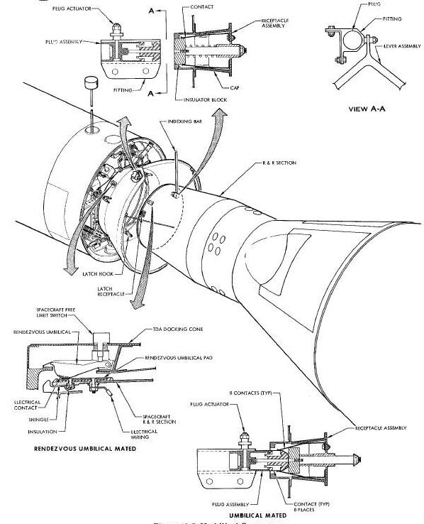
The two rendezvous umbilicals are mated automatically when the R & R section latches to the TDA. The rendezvous umbilical consists of an electrical slide contact on the R & R section and a single pin lever assembly on the docking cone. During the docking sequence, the electrical slide contact depresses the spring loaded lever assembly slightly providing an electrical connection between the spacecraft and the TDA.
The index bar assembly (Figure Below) includes the bar, a housing, a pyrotechnic extension mechanism and a pyrotechnic jettison mechanism. The pyrotechnic igniters are fired electrically from the crew station. The extension igniters generate a gas pressure which forces the bar up until the socket in which the bar fits reaches a stop. This is the extended position of the bar. The bar is jettisoned in the same way, except that the gas pressure forces the bar out of the socket and ejects it into space. The Jettison igniters also seal off the opening left by the Jettisoned bar. The jettison igniters have a l-second pyrotechnic delay to assure that the extend igniters will be fired first.
RADAR SYSTEM AND PYROTECHNIC DEVICES
The details of the Rendezvous Radar System units and the Pyrotechnic Devices are presented in Section VIII and XI respectively. The necessary information to explain how these units fit into the Docking System operation is presented elsewhere in this section.
TARGET VEHICLE STATUS DISPLAY PANEL
The status display panel (Figure above) is mounted on the TDA of the target vehicle. It is located on the docking adapter Just back of the V-notch in the docking cone. This gives the pilots a full view of the panel during the approach and docking sequence. The displays on the panel and their functions when docking with either the ATV or the ATDA are explained in the following paragraphs.
(1) DOCK (green light) when illuminated,
indicates that the docking cone is unrigldlzed and that the latch hooks
are reset.
(2) RIGID (green light) when illuminated, indicates that the docking
cone is rlgidized.
(3) PWR (green light) when illuminated, indicates that +28 volts dc
unregulated, +28 volts de regulated, -28 volts dc regulated, 115 volts
400 cps single phase and I15 volts 400 eps 3 phase power are operating.
(4) MAIN (red light) when illmnlnated, indicates the following:
a. With the main engine firing, the turbine has
exceeded 27,000 rpm (1046 sensor level), the hydraulic pressure is below
1500 + 20 psi, or the differential pressure between the fuel and
oxidizer tanks is below
2 + 2 psi.
b. With the main engine not firing, the differential pressure between
the fuel and oxidizer tsars is below 2 + 2 psi (fuel above oxidizer).
(5) MAIN (green light) when illuminated,
indicates that the main fuel tank is above 15 + 2 psia, the oxidizer
tank is abo_ 15 +/- 2 psia and hydraulic pressure is above 50 +/- 5 psia.
(6) ARMED (amber light) when illuminated, indicates that the engine
control circuits are closed and either the main or secondary engines may
be fired by command.
(7) SEC HI (green light) when illuminated, indicates that more than 110
+/- 20 psi expulsion gas pressure exists in both nitrogen spheres for a
50 second thruster firing and that more than 170 +/- 5 psi regulated
pressure exists in both propellant tank gas manifolds.
(8) SEC LO (green light) when illuminated, indicates that more than 360
+/- 20 psi expulsion gas pressure exists in both nitrogen spheres for a
150 seconds thruster firing and more than 170 +/- 5 psi regulated
pressure exists in both propellant tank gas manifolds.
(9) ATT (green light) when illuminated, indicates that the Agena
attitude control system is active.
(10) MAIN TIME (clock display) indicates by minute and second hands the
time remaining for gin engine burn. The regulated 28-volt dc power is
applied to the display unit when the main engine is running. This causes
the display unit to decrease the time remaining indication at a rate of
one second per second of burning time.
(11) SEC TIME (clock display) indicates by minute and second hands the
number of seconds of 200-pound secondary propulsion system burn time
remaining. The regulated 28-volt DC power is applied on separate wires
for high and low thrusters of the secondary propulsion system. This
causes the display unit to decrease the time-remainin8 indication at a
rate of one second per second of burn time for the high consumption and
a rate of one twelfth (1/12) second per second of burn time for the low
consumption rates.
(12) ATT GAS (synehro display) indicates the percentage of total
pressure remaining in the Agena attitude control system gas spheres.
When docking with the ATDA only four displays are
used, the others are inoperative.
(1) DOCK(green light) when illuminated, indicates that the docking cone
is unrigidlzed and that the latch hooks are reset.
(2) RIGID (green light) when illuminated, indicates that the docking
cone is rigidized.
(3) ARMED (amber light) when illuminated, indicates that ring A of the
reaction control system has been activated.
(4) ATT (green light) when illuminated, indicates that 0 degree per
second rate control has been selected in all three axes.
Agena Target Vehicle (ATV)
Augmented Target Docking Adapter (ATDA
Rendezvous and Recovery (R & R)
Target Docking Adapter (TDA)