 |
 |
TARGET DOCKING ADAPTER
Target Docking Adapter Assembly Diagram
TARGET VEHICLE STATUS DISPLAY PANEL
RADAR TRANSPONDER AND ANTENNAS
SYSTEM DESCRIPTION
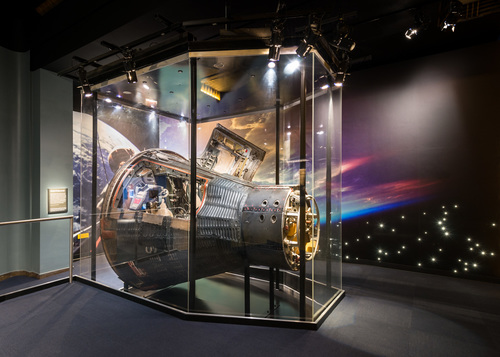
The Target Docking Adapter (Figure Below) may be mounted on either the Agena Target Vehicle or the Augmented Target Docking Adapter. The Target Docking Adapter is mounted on the forward equipment section of the target vehicle and becomes the mounting structure for all other components of the Target Docking Adapter.
Target Docking Adapter Assembly Diagram
The docking cone receives the spacecraft during docking maneuvers. Electromechanical devices in the spacecraft and the docking adapter rigidlze the docking cone as soon as the mooring operation is completed. Rigidizing operations may be automatic or as directed by the pilots or the ground control stations.
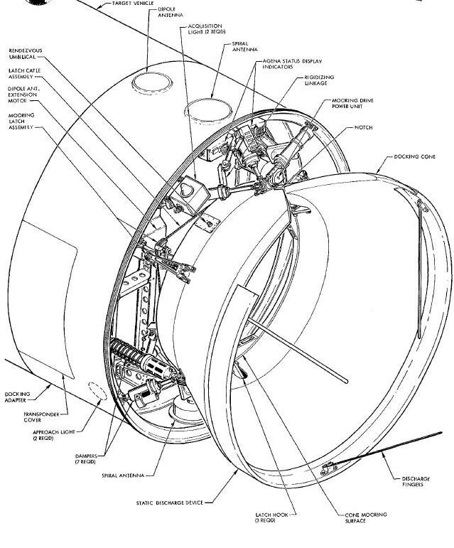
The Target Docking Adapter (TDA) consists of two major subassemblies (Figure Above): the docking cone and the docking adapter.
The docking cone (Figure Above) is connected to the docking adapter by seven cone damper assemblies, three lateral and four longitudinal, and is the mounting structure for the mooring latch assemblies the umbilical plug assembly, two rendezvous umbilical lever assemblies, the latch release actuator and a static discharge device. The latch assemblies are released and reset by the latch release actuator as a part of the unrigidize sequence. With the target vehicle control circuits operating, the cone unrigidized and ready for docking, the latch assemblies are reset. In the reset condition, the latch assemblies are spring loaded so that when the Rendezvous and Recovery section enters the docking cone, the latch hooks engage the latch receptacles. The cone has a V-notch, with a slot at the bottom of the V, cut into the cone's upper surface. This notch and slot, together with the index bar, indexes the spacecraft to obtain proper alignment between the spacecraft and the docking target.
The seven cone damper assemblies are attached in
three sets and are equally spaced at 120-degree intervals around the
rear perimeter of the docking cone. One set, has a single lateral and
two longitudinal damper assemblies and is connected to the cone behind
the V-notch. Each of the two lower sets consists of one lateral and one
longitudinal damper assembly. The dampers connect
the cone to the adapter structure and absorb the shock of the actual
docking thrusts. They are arranged to absorb thrust from any direction
and to compensate for any misalignment of the two vehicles.
Three umbilical connectors provide the connection for electrical circuits between the spacecraft and the TDA so that harallne commands may be transmitted from the spacecraft to the TDA.
The main umbilical plug assembly (Figure Below) is mounted on one of the cone structural members which supports one of the latch assemblies. In the rigidlzing operation, the mooring drive mechanism extends the plug out of its casing so that it mates with the receptacle on the spacecraft. The plug remains extended and mated until the cone is unrigidized.
Two rendezvous umbilical lever assemblies (Figure Above) are mounted on the cone assembly and are mated with an electrical contact pad on the spacecraft when the latch hooks engage the latch receptacles.
The following docking units are mounted on the docking adapter (Figure Above): the mooring drive system, the target vehicle status display panel, the acquisition lights, the radar transponder, three radar antennas and two approach lights.
The mooring drive (rigidizlng) system draws the
docking cone tightly against the adapter structure and extends the
umbilical plug. The cone is drawn into the adapter structure by the
rigidizing linkages. The linkages are driven by three gear boxes. The
gear boxes are driven by a single electric motor, through flexible drive
cables and an H-drive gear box. The motor is started automatically and
the one rlgidlzed when the spacecraft is latched into the cone. The
docking adapter Is unrlgidlzed (motor reversed) and the spacecraft
released by a single pilot command through the umbilical connection.
Prior to docking, the unrigidizing process is initiated by rf con_nand
(radar transponder Command Link or uhf ground radio link).
The target vehicle status display panel (Figure Below) is mounted on the docking adapter structure snd on one cone dsmper, just above the V-notch in the cone. It visually displays information to the pilot on twelve functions when docking with the Agena Target Vehicle (ATV). The display consists of nine lights, two clocks and one synchro indicator. All power required by the panel is supplied from the Agena power system. The ATV displays are as follows: DOCK (green light), RIGID (green light), PWR (green light), MAIN (red light), two clocks and one synchro indicator. All power required by the panel is supplied from the Agena power system. The ATV displays are as follows: DOCK (green light), RIGID (green light), PWR (green light), MAIN (red light), MAIN (green light), ARMED (amber light), SEC HI (green light), SEC LO (green light), ATT (green light), MAIN TIME (clock display), SEC TIME (clock display) and ATT GAS (synchro display). MAIN (green light), ARMED (amber light), SEC HI (green light), SEC LO (green light), ATT (green light), MAIN TIME (clock display), SEC TIME (clock display) and ATT GAS (synchro display).
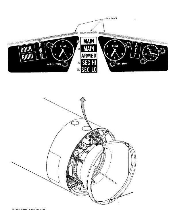
The status display panel visually displays information to the pilot on four functions when docking with the Augmented Target Docking Adapter (ATDA). The display consists of four lights: DOCK (green light), RIGID (green light), ARMED (ember light) and ATT (green light). Power required by the panel is supplied from the equipment section of the ATDA.
The two acquisition lights aid the pilots in visual tracking of the ATV. They produce a flashing light that can be seen for approximately 20 nautical miles. They are mounted at the outer edges of the adapter structure so that they are visible to the pilots around the outer edge of the cone. The lights are mounted so that they rotate outward as the cone is unrigidized. Once the cone is unrigidized the lights are spring held in the outward position.
The radar transponder and the radar antenna (2 spiral and 1 dipole) are used for pilot command tracking of the target vehicle. The radar transponder is energized and the dipole antenna (boom) is extended by uhf ground command. The two approach lights are mounted on the lower inside structure of the adapter. They are arranged to shine through the rear of the cone and on the upper inside surface near the V-notch. The lights are turned off and on by pilot or ground command. When on, they aid the pilot in attaining proper allignment of the spacecraft as they approach the docking cone.
The TDA system units are those units which are concerned with mooring, rigidizing and unrigidizing the docking cone to the docking adapter. Units which are part of the other systems (Radar, Command Link and Docking) are not discussed in detail in this section.
The docking cone (Figure
Above and
Figure Above) is designed to mate with the spacecraft R & R section.
In the moored condition, the spacecraft R & R section flts tight against
the cone bottom and is held there by the mooring latch hooks. The cone
shape tends to guide the spacecraft to the proper mooring position. This
action is aided by a V-notch and its terminating slot. When the
spacecraft index bar is aligned with the slot, the spacecraft and target
vehicle are properly oriented in roll for mooring. The cone is connected
to the docking adapter by three cone damper assemblies. A rigidizing
linkage links the cone to the mooring drive (rigidizing) system mounted
on the docking adapter main structure.
Two sets of damper assemblies are composed of one lateral and one longitudinal assembly and one set is composed of one lateral and two longitudinal assemblies (7 dampers in all). When subjected to an impact, the dampers (Figure Above) compress slowly, absorbing energy as they move. In this way, most of the energy of impact is absorbed by the fluid in the dampers and very little transmitted to the target vehicle. Springs and gas pressure return the dampers to their extended positions when the impact is dissipated.
APPROACH LIGHTS
Two approach lights are mounted on the docking adapter (Figure Above). They are positioned so that they shine through the rear opening in the cone to illuminate the notch during final approach of the spacecraft to the target docking vehicle. Some light, however, reaches the entire inner surface of the cone. The pilots turn the lights off and on by using the cone. Electric power is supplied by the target vehicle power system.
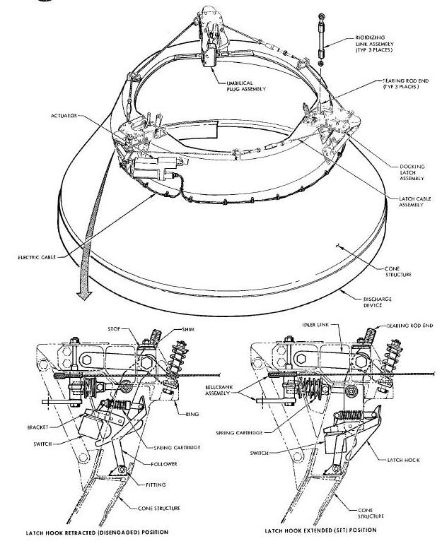
There are three mooring latch assemblies (Figure
Above). Each assembly is mounted to the cone as shown in the
illustration. Each assembly contains a bellcrank which actuates the
mechanism. The bellcranks of the three assemblies are connected together
by a cable assembly. One bellcrank is connected to the latching actuator
by a linkage. When the actuator is extended, the bellcranks are rotated
so that the latch assemblies are in the reset condition. This is the
condition which must exist Just prior to mooring. As the spacecraft
slides into the docking cone and contacts the latch hooks, the hooks are
pushed aside to allow the latch catches to get in front of the hooks. As
this happens, the hooks drop in behind the catches (elevated part of the
receptacle) and hold the spacecraft in place. The umbilical plug is
mounted on one of the cone structure members which supports a latch
assembly. The latch actuator is
electrically driven and either retracts or resets the latch hooks. Power
to the latch actuator is switched by the latched sensing switch, the
unlatched limit switch and the unrigidized limit switch. During the
unrigidize sequence, the actuator is energized automatically to rotate
the bellcranks and retract the latch hooks to the disengaged condition.
When the latches are disengaged,
there is a 30-second delay before the latch hooks are automatically
reset. The latched sensing switch is operated only when the latch
receptacle is present. If the latch receptacle is present, the latched
sensing switch will initiate the rigidize sequence when the latch hooks
are reset.
TARGET VEHICLE STATUS DISPLAY PANEL
The status display panel (Figure Above) is located on the docking adapter Just back of the V-notch in the docking cone. The notch gives the pilots a full view of the docking panel during near approach to the docking cone. The displays on the panel and their functions are presented in detail in the Docking System Section.
The mooring drive system (Figure Below) is composed of a power unit (DC motor and gears), four flexible drive shafts, an H-drive, three gear boxes, six limit switches and a mooring drive linkage. A drive arm is attached to the output shaft of each gear box.
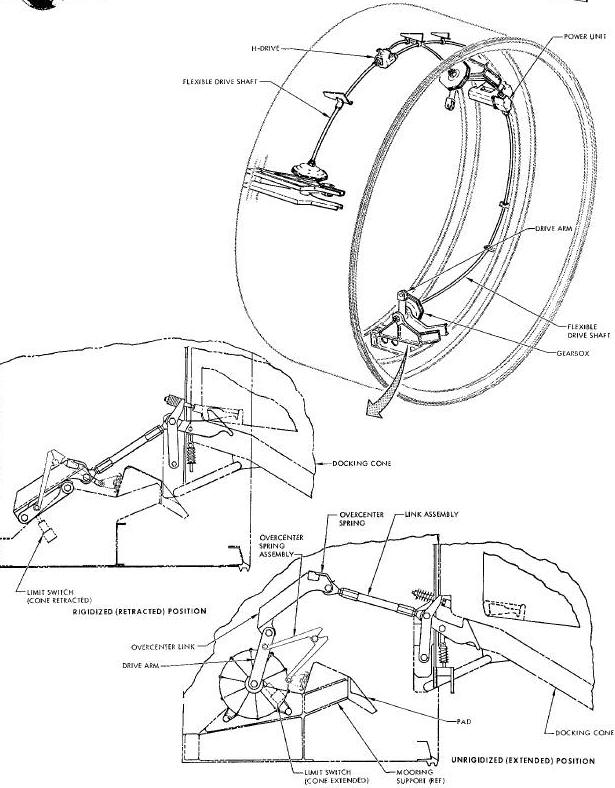
The power unit supplies power to the gear boxes through the flexible drive shafts and the H-drive unit. The gear boxes rotate the drive arms which in turn, retract or extend the rigldizing linkage. When the linkage is retracted, the docking cone is rigidized to the docking adapter and the spacecraft/target vehicle combination can be operated as a single unit. The linkage also moves an actuator which extends the umbilical plug out of its casing. When the linkage is extended, the umbilical plug is retracted into its casing and the docking cone is moved away from the adapter so that it is completely supported by the dampers. The limits switches sense when the linkage is either fully extended or fully retracted and in each case remove power from the drive motor when the limit is reached.
The power unit is operated to retract (rigidlze) the system by the actuation of three sensing switches on the mooring latch assemblies. The sensing switches energize the mooring drive power unit when the spacecraft is latched to the docking cone. The linkage can also be retracted by the RIGIDIZE command to the target vehicle command programmer. Limit switches stop the power unit when the linkage is fully extended. The same limit switches also apply power to the unlatch side of the latch release actuator of the mooring latch assemblies.
The acquisition lights (Figure Above) are used for visual guidance and tracking of the target vehicle when the vehicles are 20 nautical miles or less apart. Two lights are provided. They are mounted on the docking adapter and are held in the retracted position during the boost and insertion phases of a mission. The docking cone holds the lights in the retracted position until the cone is unrigidizedby the pilots via the Command Link.
Each light consists of a capacitor discharge flashing light system. The lamp flashes at a rate of 65 flashes per minute and has a minimum of 100 candles effective intensity through an included angle of +/- 90 degrees from the lamp longitudinal axis. A reflector increases the intensity so that the lamp is visible from 20 nautical miles with the intensity of a third magnitude star. The pilots turn the lights off and on via the Command Link.
RADAR TRANSPONDER AND ANTENNAS
The radar transponder and antennas are considered part of the Rendezvous Radar System, the details are presented in Section VIII.
A discharge device (Figure Above) is mounted on the docking cone to neutralize the electrostatic potential between the spacecraft and the target vehicle. This device consists of three flexible metal fingers that protrude from the docking cone. They make the first contact between the spacecraft and target vehicle. The device is so wired that any static charge between the two orbiting vehicles will be dissipated at a controlled rate.
TDA - Target Docking Adapter (TDA)