CABIN INTERIOR ARRANGEMENT
Cabin Equipment Diagram (Typical)
Gemini Ejection Seat Assembly Diagram
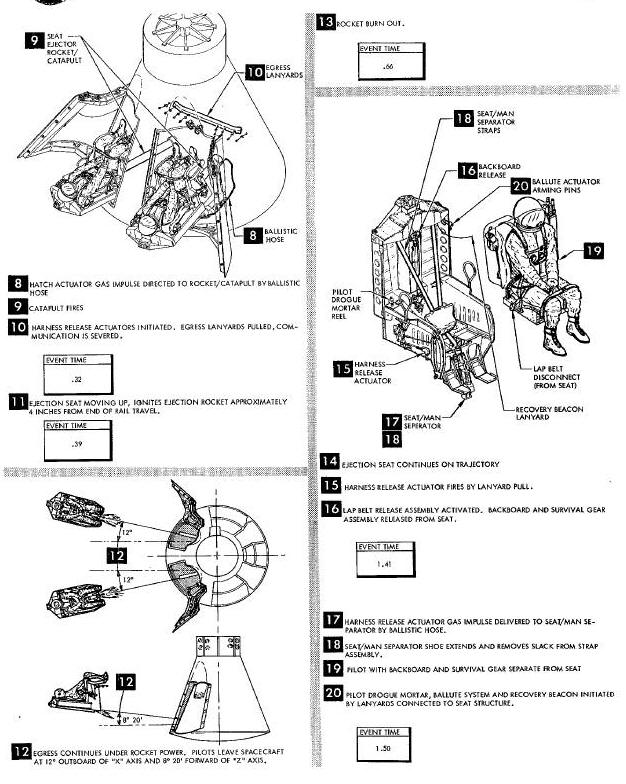
Ejection Seat Sequence Of Operation
FOOD WATER AND EQUIPMENT STOWAGE
Spacecraft Interior Stowage Areas Diagram
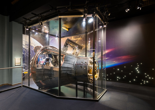
The equipment within the cabin is arranged to permit the command
pilot, seated to the left, and the pilot, seated to the right, to
operate the controls and observe displays and instruments in full
pressure suits in the restrained or unrestrained position. The cabin air
outflow is regulated during launch to establish and maintain a 5.5 psi
differential pressure between the cabin and outside ambient condition.
The cabin is maintained at a nominal 5.1 psia throughout the flight by a
cabin pressure regulator. The cabin equipment
(Figure
Below) basically consists of crew
ejection seats, instrument panels and controls, lighting, food, water,
waste collection, and miscellaneous equipment.
Cabin Equipment Diagram (Typical)
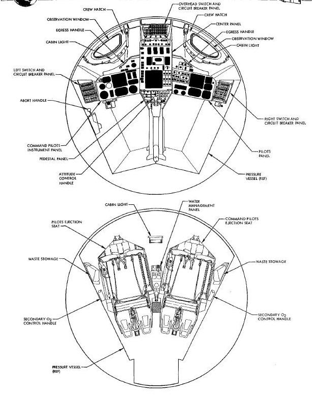
The crew members are seated in the typical command pilot and pilot fashion, faced toward the small end of the re-entry module. The seats are canted 12° outboard and 8° forward to assure separation and to provide required elevation in the event an off the pad ejection is necessitated. Crew seating provisions include scats, restraint mechanisms, seat ejection devices, seat man separator, survival gear, and an egress kit assembly effective spacecraft 5 and 6 only.
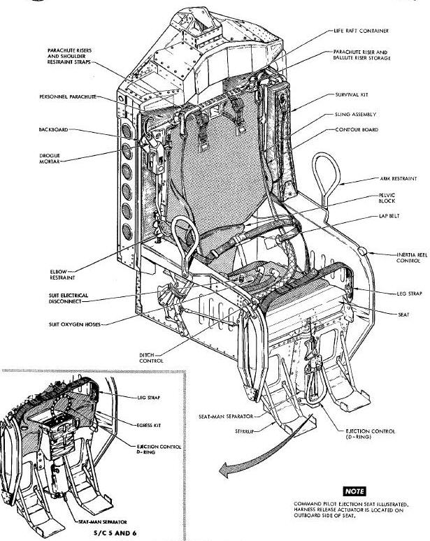
The crew seats (Figure Below) are all metal built-up assemblies consisting of a torque box framed seat bucket, channeled backs and arm rests. The seat has lateral and vertical stiffeners, designed for a single moment of thrust. The seat is supported at a single point at the top of the seat back. At this point, the seat bolts to the rocket/catapult. Each seat is supported against fore, aft, and side movement by slide blocks mounted on the seats and retained in tee type rail assemblies attached to the large pressure bulkhead. The seats incorporate a padded contoured headrest to support the pilots helmet. Each seat slso incorporates a restraint system, harness release system and a seat/man separator.
Gemini Ejection Seat Assembly Diagram
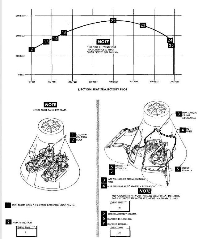
The seat ejection system (Figure Below) provides the crew with a means of escaping from the vicinity of the spacecraft in the event of an abort or in an emergency condition during launch or re-entry. Crew member seats are ejected by means of rocket/catapults. Hot gas from each of the hatch actuators is routed to the appropriate seat catapult where dual firing pins strike dual percussion primers, thereby igniting the seat rocket/catapult main charge and ejecting the seats from the spacecraft. Hot gas from the rocket/catapult main charge ignites the sustainer rocket and the rocket provides additional separation from the spacecraft. In the event ejection becomes necessary, after deployment of main landing system parachute and while descending in the two point suspension, it is mandatory that the main landing system parachute be Jettisoned before ejecting from the spacecraft. The ejection sequence is initiated by manually pulling either ejection control (D-ring) located on the front of the seat buckets. During the launch phase of flight each pilot erects and holds on the D-ring. This action aids in stabilizing the pilots arms and at the same time places them in a position for instant response. The D-rings are normally stowed at the front of the seat and are pinned in a downward position at the front of the seat structure. The safety pin is removed during launch and re-entry and during orbit.
Ejection Seat Sequence Of Operation
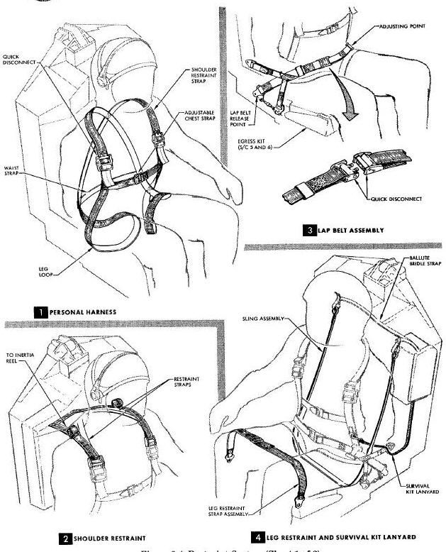
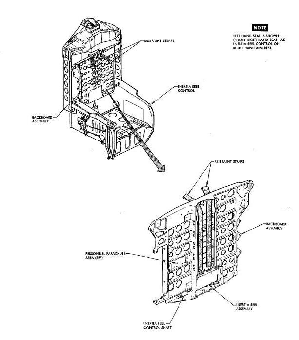
Each pilot is restrained in his ejection seat by a restraint system (Figure Below) consisting of personal harness, lap belt assembly, shoulder restraint, inertia reel and leg restraint. Other portions of the restraint system are part of the ejection seat (Figure above). These seat restraints are the arm restraint loops, elbow restraint and foot stirrups. The restraint system provides adequate support and restraint during conditions of maximum acceleration and deceleration.
The inertia reel (Figure Below) is a two position locking device, located on the rear of the backboard. Two straps connect the inertia reel and the personal harness to restrain the pilots forward movement. The inertia reel control handle is located on the front of the left arm rest and has two positions, manual lock and automatic lock. Orbital flight is accomplished with the inertia reel in the automatic lock position. Manual lock position is used during launch and re-entry. The manual lock position prevents the pilots shoulders from moving forward.
To release his shoulders, when the inertia reel is in the manual lock position, the pilot must position the control handle to the automatic position. The automatic lock allows the astronaut to move forward slowly a maximum of 18 inches but will lock with a 3 g deceleration. When the automatic lock has engaged, the lock will ratchet and permit movement back into the seat, but will not permit forward movement. The release of the automatic lock is accomplished by cycling the control handle to manual and back to automatic lock.
The arm restraint (Figure Above) is a welded, 1/2 inch diameter tube assembly made up in the form of a loop. A loop is installed on each arm rest to retain the pilots arms within the ejection envelope. When the arm restraint loop is not required, it ,my be swung to the rear and down.
An elbow restraint is provided for the command pilot only. It is used to stabilize his forearm during manual re-entry.
The leg restraint (Figure Above) consists of two straps of Dacron webbing with a connecting slide buckle. One end of each strap is secured to the seat by round metal eyelets. The left strap of each leg restraint has a metal end assembly that permits the right strap to fold back on itself. Velcro tape on the right strap is used to secure the strap end in position when the strap is drawn tight over the pilots legs. During seat/man separation, the restraint strap eyelets are automatically released from the base of the seat, freeing the restraint strap.
The ejection seat foot stirrups (Figure Above) consist of two welded frames attached to the front of the ejection seat. Each stirrup has a short protruding platform with small vertical edges rising along the outboard side. The stirrup is so constructed that the pilots shoe heel will lock in place and prevent forward movement of the foot while the small vertical edges will prevent side movement. During seat ejection, the pilots feet will stay in place.
The lap belt (Figure Above) is an arrangement of Dacron and nylon straps, designed to restrain the pilot in the seat structure. Load carrying straps from the lap belt are fastened to the backboard and seat. The lap belt has a manual quick disconnect and a pyrotechnic release fitting near the center of the pilots lap. The manual quick disconnect can be released with one finger. Lap belt tension is adjusted by sliding excess strap through the pyrotechnic release. During ejection, the lap belt ends attached to the seat structure are released just prior to seat/ man separation. During separation, the lap belt remains with the pilot. Five seconds after the backboard drogue mortar fires, the pyrotechnic lap belt release activates and allows the lap belt, backboard and seat to fall free.
A second manual release for the lap belt is also available to the pilot. It is located forward on the right arm rest and is referred to as the ditch control. Releasing the lap belt with the ditch control allows the pilot to egress from the landing module with the backboard and seat.
EGRESS KIT (Effective Spacecraft 5 and 6)
The egress kit assembly contains the bail out oxygen for an ejected pilot. The egress kit rests in the ejection seat bucket and forms a mounting surface for the egress kit cushion. The egress kit contains an oxygen supply, for breathing and suit pressurization; a composite disconnect, which when separated closes the port and prevents escape of egress oxygen; a relief valve, to prevent pressure build up in the pressure suit; a regulator, to reduce high pressure to a controlled flow of low pressure oxygen, a pressure gage, for visually checking egress oxygen pressure; and connecting lines. Three lanyards are attached between the egress kit and the spacecraft. These lanyards pull release plns to allow the composite disconnect to separate, allow the oxygen to flow through the pressure regulator and allow the relief valve to control the pilots suit pressure. When the drogue mortar deploys the pilot parachute, a 5-second pyrotechnic time delay is initiated and at burn out, the egress kit with the backboard is separated from the pilot.
EGRESS KIT CUSHION (Effective Spacecraft 5 and 6)
The egress kit cushion (Figure Above) has a universal type of contour and is attached to the top of the egress kit. The cushion is positioned forward of the pelvic block and up to the ejection control handle access door.
The backboard assembly (Figure above) is machined aluminum, designed and stressed to retain the inertia reel, ballute, ballute release and deploy mechanism, drogue mortar, parachute and survival kit. A cushion, contoured to the ind/vidual pilots body requirements, is positioned on the forward surface of the backboard. The cushion is provided to supply support and comfort to the pilots back. The inertia reel straps and lap belt secures the pilot to the backboard. The backboard accompanies the pilot through seat ejection to parachute deployment. Five seconds after parachute deployment, the backboard with the seat is separated from the pilot.
The pelvic block (Figure above), contoured to the lower torso of each pilot, is positioned between the backboard assembly and the seat. The block supports the pilots lower vertebra and pelvic structure. It remains with the seat structure upon seat/man separation.
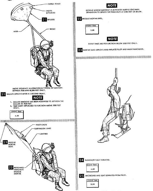
The ballute system (Figure above) consists of a barostat controlled pyrotechnic initiator, combined with a pyrotechnic gas generator, cutters and a packaged ballute. The ballute, located on the back and lower left side of the pilots backboard, is an aluminized nylon fabric enclosed cone. It is inflated by ram air passing through four inlets located symmetrically around the upper periphery. The ballute is connected to the backboard through an 8 inch riser, a 5 foot dual bridle, and by a one inch wide Dacron webbing passing through a pyrotechnic actuated cutter. The ballute provides the pilot with a stabilized, feet into the wind, attitude for all ejections over 7,500 feet. The system is fully automatic and is actuated at seat/man separation. At altitudes below 7,500 feet, the barostat prevents deployment of the ballute.
The personnel parachute (Figure above) is a standard 28 ft dia nylon parachute. The parachute is located on the right rear of the pilots backboard. It is deployed by the drogue mortar slug and pilot chute. The parachute risers are attached to the pilots personal harness.
The parachute drogue mortar (Figure above) is a pyrotechnic device designed to eject a 10 oz drogue slug with sufficient velocity to deploy the pilot chute of the personnel parachute. The drogue mortar is a barostat operated firing mechanism, but can be fired manually. It will fire and deploy the parachute at or below 5,700 feet plus a 2.3 seconds time delay from seat/man separation. An MDF chain is initiated by the drogue mortar and separates the backboard and seat from the pilot.
The personal harness assembly (Figure Above) provides a light, strong, and comfortable arrangement to attach the personnel parachute to the pilot. The harness is constructed from nylon webbing formed into a double figure-8. The two figure-8's are joined by two cross straps, the waist strap, and the chest strap. Only the chest strap is adjustable. A quick disconnect is placed forward and below each shoulder for connection of the parachute risers and shoulder restraint straps. Below the left quick disconnect, a small ring is incorporated to attach the survival kit lanyard.
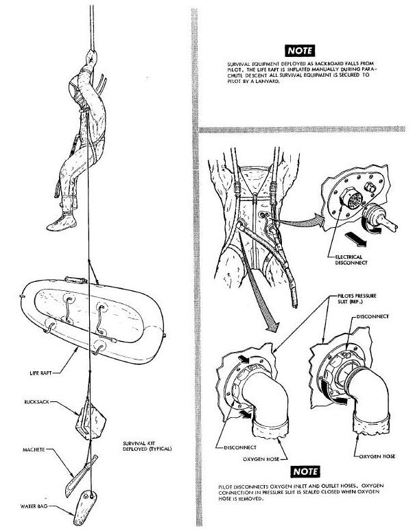
The survival kit (Figure above) is a packaged group of specially designed equipment for the use of a downed pilot. Articles in this kit are intended to aid in preserving life under varying environmental conditions. Deployment of the survival kit is automatic if the pilot ejects and is also available to the pilot if he lands with the spacecraft.
Deployment of the survival kit during the ejection cycle takes place as the backboard and seat falls away from the parachuting pilot. As the backboard falls, the survival kit lanyard, connected to the pilots harness, pulls a pin on the life raft container. When the pin is removed, the daisy chain loops are disengaged and the life raft and rucksack are extracted from the container. The survival kit lanyard repeats the extraction process in removing the machete and water bottle from the second container. The machete and water bottle are stowed in a survival equipment container on the left front side of the backboard.
During seat/man separation, a lanyard between the seat structure and the rucksack activates the radio beacon. As the pilot descends on his parachute, the survival equipment is suspended below and the radio beacon transmits on an emergency frequency. Direction finding equipment on aircraft and aboard ship can plot the pilots position taking navigational fixes on the radio/beacon.
Survival equipment is divided into two major stowage containers. The life raft container mounted on the left rear of the backboard has the following items:
Life raft container (Typical)
1 Life Raft
1 Sea anchor
1 4 inch x _ inch Foam rubber pad
1 C02 cylinder
1 Sea dye marker
1 Sun bonnet
Rucksack (Typical)
1 Survival light
1 Strobe light
1 Flash light
4 Fish hooks
Fish line
2 Sewing needles and thread
1 Magnetic compass
1 Fire starter
4 Fire fuel
1 Whistle
1 Signal mirror
14 Water purification tablets
1 De-salter kit (less can)
8 De-salter tablets
1 Water bag
1 Repair kit
1 Medication kit (Typical)
6 Tablet packets
1 Small injector (1 CC)
1 Large injector (2 CC)
1 3 inch x 3 inch compress
1 12 inch x 12 inch aluminum foil
1 Tube zinc oxide
1 pr Sun Glasses
1 Radio beacon
The forward survival kit, mounted on the forward surface of the backboard to the left of the pilots shoulder, contains the following;
1 Water container with 3 lb of water
1 Machete with sheath
There are 18 pyrotechnic devices incorporated in the cabin all of which pertain to seat ejection, restraint release and parachute deployment. The pyrotechnic devices are 2 hatch actuators, 2 seat rocket/catapults, 2 ballute deployment and release mechanisms, 2 backboard and seat Jettison, 2 drogue mortars, 2 harness release actuators, 2 seat/man separator actuators, 2 hatch actuator initiators and 2 hatch MDF (Mild Detonating Fuse) harnesses. The pyrotechnic devices, except the drogue mortar, are safetied by stowing the ejection control handle (D-ring) with a safety pin through the handle into the ejection control assembly. On spacecraft 8 only, a second ejection control pyrotechnic safety pin is also inserted in the side of the ejection control assembly to completely safety the MDF manual firing mechanism.
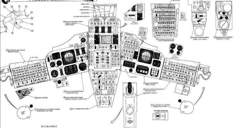
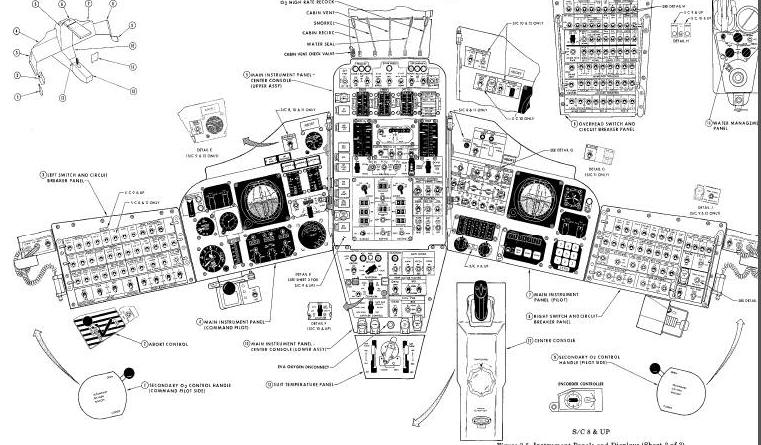
Instrument panels, switch and circuit breaker panels and pedestal
panels (Figure Below) are arranged
to place controls and indicators within reach and convenient view of
each crew member while in a full pressure suit. A swizzle stick, stowed
by the overhead switch and circuit breaker panel, enables a pilot to
position switches and rotate selectors on the opposite side of the
cabin. With this
arrangement, one pilot can control the complete spacecraft and
temporarily free the second pilot of all duties.
Cabin interior lighting is provided by three types of lights located in five separate locations, described as follows: Cabin flood lights are located aft and above the center-line stowage area. A DIM control is located under the light to control light intensity. Instrument flood lights are located at the forward inner edge of the hatches. Each instrument flood light installation contains two lamps, one lamp having a red filter and the other a white filter projecting downward. A DIM control and a RED-WHITE-OFF switch are provided at each of the lights. Two utility lights attached to the ends of spiral extension cords are located on the left and right side walls of the spacecraft interior. The lights stow in clips mounted on the side walls. An ON-OFF switch is located adjacent to the AUX RECEP panel on each of the spacecraft side walls. The CTR LIGHTS, BRIGHT-0FF-DIM switch and the CABIN LIGHTS switch-circuit breaker are located on the overhead switch and circuit breaker panel.
The two receptacles, powered by the spacecraft electrical system, are installed on brackets immediately aft of the left and right switch/circuit breaker panels. These receptacles are controlled by adjacent ON-OFF switches and are used for powering the utility light or other electrical equipment.
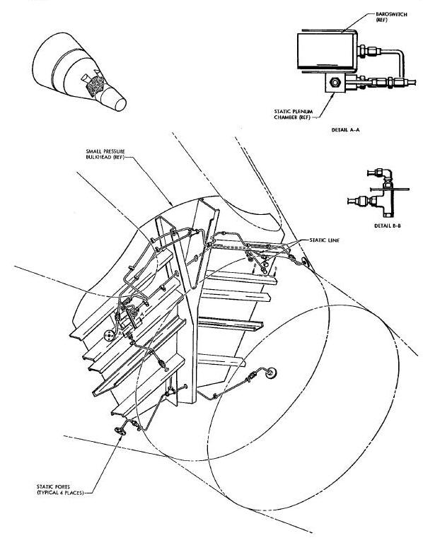
The static pressure system is employed to operate the rate of descent
indicator, altimeter, and to supply pressure to the static pressure
transducer for instrumentation. The static system is also utilized to
provide a differential pressure for the cabin pressure transducer. The
static ports (Figure Above), used for
atmospheric pressure pick-up, are located in the small end of the
spacecraft
conical section. The static port (Figure
Above), used for differential
pressure pick-up, is located on the forward surface of the small
pressure bulkhead.
FOOD WATER AND EQUIPMENT STOWAGE
Containers to left, right and aft of pilots (Figure Below) are provided for equipment and food storage. Although minor changes in storage containers are dictated by mission requirements, the main containers are as follows: Center-line stowage box, used for larger size camera containers and EVA (Extra-Vehicular Activity) chest pack; right aft pressurized stowage box, used to stow food initially and later, body waste materials; left aft stowage box, used to stow food packages; right and left sidewall stowage boxes, used to stow small pieces of equipment; left and right fabric covered sidewall stowage boxes, used to stow lightweight head sets; hatch food pouches used to stow large quantities of food; and sidewall stowage box extensions used to stow penlight, spotmeter, exposure dial and tape recorder cartridges. Equipment stowed in the above boxes may change with each mission.
Spacecraft Interior Stowage Areas Diagram
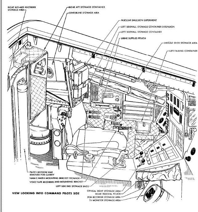
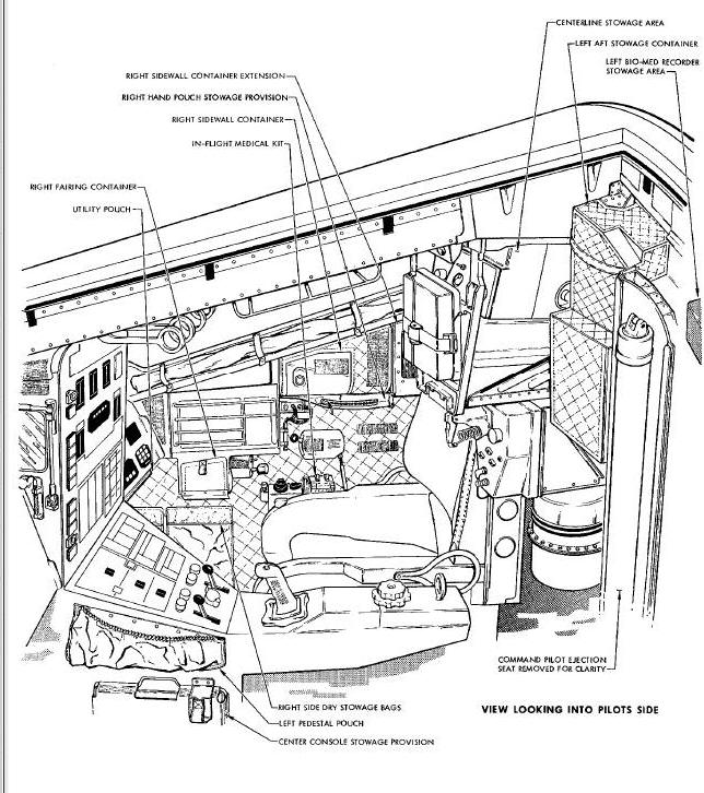
Larger pieces of equipment, emergency equipment or equipment used on every flight, have special stowage brackets or fabric pouches positioned throughout the interior of the spacecraft. Examples of specific stowage brackets are as follows : inflight medical kit, stowed aft of abort control handle; and the optical sight, stowed under command pilots instrument panel. Without counting the food packages, stowage facilities are furnished for more than 125 pieces of equipment.
During flight, various pieces of frequently used equipment are
removed from launch stowage areas and are stowed, with Velcro tape, on
the spacecraft sidewalls, and on the inside surfaces of the hatch. As
debris accumulates during flight, it is placed in the left aft debris
area, located aft of the pilots seat. Prior to descent, the equipment is
re-stowed. Only a general rule can be applied to
stowage descriptions. Exposed film is placed in insulated containers,
previously occupied by cameras and lens, in the center line stowage box.
The left aft stowage box is filled and the remainder of the loose
equipment is divided among the sidewall stowage boxes on a planned
basis. The pressurized stowage box is used to store urine samples and
waste containers.
A water storage container, with a 16-pound capacity, is located forward of the aft pressure bulkhead, between the seats. As the water is used from the main storage container, it is replenished by the water stowed in the adapter section. Drinking is accomplished by means of a tube and manual valve system. Food and water will be sufficient for the mission and a postlanding period of 48 hours.
Feces will be collected in a glove-like plastic bag. Urine samples are taken, and the remainder disposed of by overboard dumping. The urine samples and feces waste containers are stowed in the right aft pressurized container which allows cabin depressurization without possible boiling off of the waste materials moisture content.
Personal stowage facilities are provided by retaining removed portions of the pressure suit and other equipment as required. These provisions consist of floor pouches, Velcro covered areas on the walls of the pressure vessel, adjacent to the pilots and attached to the structure in usable areas. Items to be stowed utilize the hook and pile principle of mating Velcro patches.