Communications
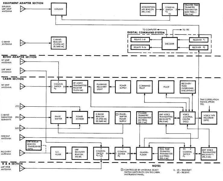
Communication System Block Diagram
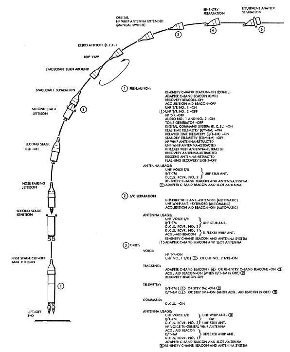
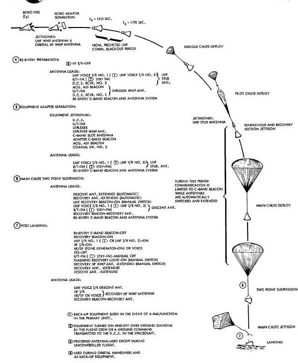
Communication System Sequential Diagram
Real-Time Telemetry Transmitter
SPACECRAFT/LAUNCH VEHICLE SEPARATION
UHF Voice Transmitter Receiver
Delay Time Telemetry Transmitter
Real-Time Telemetry Transmitter
UHF Descent and UHF Recovery Antennas
UHF Descent and Recovery Antenna Diagram
Multiplexers (UHF Diplexer and UHF Quadriplexer)
UHF Diplexer/ UHF Quadplexer Diagram
Re-Entry C-Band Radar Beacon Block Diagram
Adapter C-Band Radar Beacon Block Diagram
Acquisition Aid and UHF Recovery Beacons Diagram
Voice Control Center Functional Block Diagram
UHF Voice Transmitter/Receivers
UHF Voice Transmitter Receiver Diagram
HF Voice Transmitter/Receiver Diagram
Telemetry Transmitters Diagram
Telemetry Transmitter Block Diagram
FLASHING RECOVERY LIGHT AND POWER SUPPLY
Flashing Recovery Lights and Power System Diagram
DCS Receiver/Decoder Block Diagram
The Communication System is the only communication link between the
ground and the Gemini Spacecraft. The system has the following
capabilities: radar tracking of the spacecraft; two-way voice
communications between the ground and the spacecraft,
and between the crew; ground command to the spacecraft; Instrumentation
System data transmission; and postlanding and recovery aid data
transmission. To make possible these various capabilities, the
Communication System contains components that may be divided into the
following categories: antennas, including multiplexers and coaxial
switches; beacons; voice communications; telemetry transmitters;
flashing recovery light; and Digital Command System. The flashing
recovery light and the uhf recovery beacon are grouped together in a
category called the Electronic Recovery Aids (ERA).
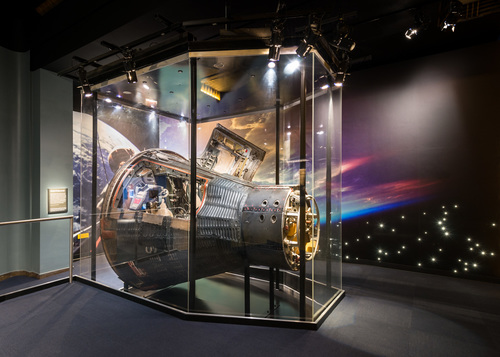
The Communication System components are located throughout the
spacecraft with the largest concentration being in the right equipment
bay of the re-entry module and the electronic module of the adapter
equipment section as illustrated
in Figure below.
The Communication System components are located throughout the spacecraft with the largest concentration being in the right equipment bay of the re-entry module and the electronic module of the adapter equipment section as illustrated in Figure above.
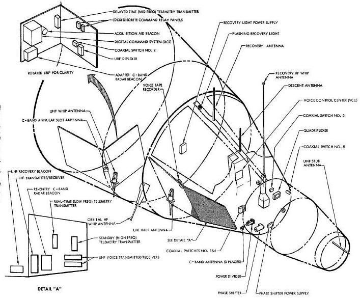
Eight antennas and one antenna system provide transmission and/or reception capabilities for the various Communication System components. The spacecraft Communication System (Figure below) contains the following antennas: uhf recovery; uhf stub; uhf descent; two uhf whips; two hf whips; C-band annular slot; and a C-band antenna system consisting of a power divider, a phase shifter, a phase shifter power supply, and three helical antennas. Antenna usage is illustrated in Figure Below and described in the individual antenna description.
Communication System Block Diagram
Antenna usage is illustrated in the Figure below and described in the individual antenna description.
Communication System Sequential Diagram
To achieve the most efficient antenna usage, a diplexer and a quadriplexer are used with the uhf whips and the uhf stub antenna. The multiplexers make it possible to use more than one transmitter and/or receiver with a single antenna. Five coaxial switches permit antenna and transmitter/receiver switching for best ccmnunication coverage during the various phases of the mission (launch, orbit, re-entry and recovery).
Four beacons in the Communication System establish the capability of locating and tracking the spacecraft during the mission. The four beacons are: An acquisition aid beacon and a recovery beacon used to locate the spacecraft, and two C-band beacons used to track the spacecraft. The acquisition aid beacon, operating on a fixed frequency, is used to determine when the spacecraft is within the range of a ground tracking station, and provides information for orientating the ground station antennas during the orbital phase of the mission. The recovery beacon is a transmitter that operates on the international distress frequency, and is used by the recovery forces to determine the spacecraft location. The C-band beacons are transponders which, when properXy interrogated by a ground station, transmit signals for accurate spacecraft tracking.
During the recovery phase of the mission, emergency communications may be established by connecting one of the uhf rescue beacon transceivers to the uhf recovery antenna. The rescue beacon transceivers are Government Furnished Equipment (GFE), stowed in pilot's survival kits.
Voice communications is maintained by one hf and two uhf transmitter/receivers and the Voice Control Center (VCC). The VCC has ell the necessary controls and switches required for various keying modes, transmitter/receiver selection, squelch, volume control, and voice recording. The hf voice transmitter/receiver may also be used for Direction Finding (DF) purposes during the postlanding phase of the mission.
An intercom connector is available for communication between the crew and recovery tesm prior to opening the spacecraft hatches during the recovery phase of the mission. Lightweight headsets are supplied for use when the spacesuit helmets are removed during orbit, or during postlanding if the helmets or entire spacesuit is removed prior to recovery.
Receiving inputs from the Pulse Code Modulated (PCM) programmer and the on-board tape recorder, three telemetry transmitters transmit vital spacecraft system parameters to the ground stations. The three transmitters operate on different frequencies and are identified as real-time, delayed-time, and stand-by transmitters. The stand-by transmitter is only used in case of real-time, or delayed time transmitter failure.
The flashing recovery light, used during the postlanding phase of the mission, contains its own power supply and improves visual spacecraft location.
The Digital Command System (DCS) is the command llnk between the ground and the spacecraft. The DCS consists of two uhf receivers, a decoder, and two relay packages and Is operational from pre-launch until adapter equipment section separation. Basically, the DCS receives and decodes two types of commands: a discrete or Real-Time Command (RTC) for spacecraft equipment utilization, and Stored Program Commands (SPC) that supply digital information to various spacecraft systems. Real-time commands operate DCS relays that control power directly or energize relays in the spacecraft Electrical System that determine equipment usage. Stored program commands are received and decoded for use by the Time Reference System (TRS), or the computer.
The Communication System is semi-automatic in operation. The sequence and theory of operation of the Communication System is described in the following paragraphs and referenced in these Figures Individual components are described in System Units.
Voice tape recordings are made during the mission by placing the RECORD switch on the VCC to the CONT or MGM position. The TONE VOX, AUDIO & UHF T/R 1 and 2 circuit breakers must be in the ON position. Each tape cartridge allows approximately one hour of recording time and is easily changed. An end-of-tape light on the voice recorder illuminates for two seconds when two minutes of recording time remains on the tape. The end-of-tape light will remain on when the end of the tape is reached. A digital timing signal is applied to one channel of the tape for time correlation of the voice recording.
During pre-launch the BEACONS-C circuit breaker
is placed to the ON position to arm the C-RNTY and C-ADPT BEACON CORTROL
switches. The C-RNTY switch is placed in the CONT position during
pre-launch to enable the re-entry C-band beacon to reply when properly
interrogated by a ground station. The C-ADPT switch is placed in the CMD
position during pre-launch. The CMD position
enables the ground station during launch, to activate the adapter C-band
beacon via a DCS channel if the need arises. After the adapter C-band
beacon is activated, it will reply when properly interrogated by a
ground station.
The C-band antenna system, used with the re-entry C-band beacon, is energized when the ANT SEL switch is placed in the RETY position. The ART SEL switch is armed when the COAX CBTL circuit breaker is positioned to ON. The ANT SEL switch controls application of power to the phase shifter power supply in the C-band antenna system.
The number 1 uhf voice transmitter/receiver will
be utilized during pre-launch unless some malfunction occurs in which
case the number 2 transmitter/receiver can be selected. For operation of
either uhf voice transmitter/receiver standby power is applied through
the AUDIO & UHF T/R circuit breakers 1 and 2, which must be in the ON
position. The selected transmitter/receiver will be powered
by placing the UHF select switch to the number 1 or number 2 position
and the MODE switch of number 2 AUDIO to the UHF position. The UHF
select switch also controls coaxial switch 1 which connects the uhf
transmitter/receiver to the quadriplexer. Coaxial switch power is
obtained from the common control bus through the ON position of the UHF
RELAY circuit breaker. The method of keying
the uhf transmitter/receiver is selected by positioning the KEYING
switch on the VCC to VOX (voice operated relay), PTT (push-to-talk), or
CONT INT/PTT (continuous intercom/push-to-talk transmitter keying).
The desired antenna usage is obtained by placing the ANT CNTL circuit breaker to the ON position. This places coaxial switch 3 to position 1; thus connecting the quadriplexer to the IN position of the coaxial switch 5. Coaxial switch 5 was placed in position 1 when the ANT SEL switch was placed in the RNTY position during the C-band beacon operation. With coaxial switch 5 in position 1, the uhf stub antenna is available for voice transmission and reception. Prior to umbilical release, voice communication is maintained between the spacecraft and the ground complex through a hardline using the headset and microphone amplifiers of the VCC. After umbilical release, voice transmission to the ground complex is accomplished by means of the uhf voice transmitter/receiver.
Real-Time Telemetry Transmitter
The real-time telemetry transmitter will be operating during the pre-launch phase of the mission. The real-time telemetry transmitter is powered by placing the RT XMTR circuit breaker in the ON position and placing the TM CONTROL switch to the R/T & ACQ position.
The real-time telemetry transmitter uses the uhf stub antenna via the quadriplexer and coaxial switches 3 and 5, the same as the uhf transmitter/receiver.
In case of real-time telemetry transmitter
failure, the stand-by telemetry transmitter may be used for real-time
transmission. The STBY XMTR CNTL and PWR circuit breakers must be in the
ON position to operate the stand-by telemetry transmitter. If selection
is made by the crew, the STBY TM CONTROL switch is placed to the R/T
position. Selection can be made by a ground command via the
DCS when the TM CONTROL switch is in the OFF position. When operating as
the real-time telemetry transmitter, the stand-by transmitter uses the
stub-antenna for transmission.
The following Communication System components will be non-operational during the pre-launch phase of the mission. To assure the off condition of these components, the following switches should be in the position specified below:
| HF (onvcc) | Off |
| BEACON CONTROL - RESC | Off |
| HFANT | Off |
To assure proper sequential actuation of the various communication components, the following circuit breakers (in addition to those previously described) must be placed to the position listed prior to launch:
| WHIP ANTENNAS | HF |
| WHIP ANTENNAS | UHF |
| WHIP ANTENNAS | DIPLEX |
| HF T/R | On |
| BEACONS | ACQ |
| BEACONS | RESC |
| XMTRS | DT |
| TAPE RCDR | CNTL |
SPACECRAFT/LAUNCH VEHICLE SEPARATION
Equipment usage after spacecraft/launch vehicle separation is identical to that described under Pre-Launch except for the following: Upon closure of any two of the three spacecraft separation sensors the acquisition aid beacon is energized. The uhf whip antenna solenoid actuators are powered and release the latch mechanism of the uhf whip antennas, allowing them to self extend.
The acquisition aid beacon transmits via the diplexer and uhf whip antenna on the adapter equipment section. Placing the TAPE RCDR-CTL circuit breaker to ON and the TM CONTROL switch to R/T & ACQ during pre-launch places coaxial switch 2 in position 1 which connects the acquisition aid beacon to the diplexer.
During orbit, operation of the telemetry transmitters and beacons will normally be controlled by ground commands via DCS channels. To operate from ground commands the C-ADPT, C-RNTY and T/M CONTROL switches must be in the CHD position.
During orbit hf communications is via the hf whip antenna on the adapter retrograde section. At insertion the adapter hf whip is extended by placing the LANDING switch to the SAFE position, and the HF ANT switch to the EX_ position. This will place coaxial switch in position 2 and allow hf voice transmission and reception via the adapter hf whip. After extension (approximately one minute) the HF ANT switch is returned to the OFF position.
Stand-by power is applied to the hf transmitter/receiver by the SF T/R circuit breaker which was positioned to ON during pre-launch. The hf transmitter/receiver is powered by positioning the HF select switch (on the VCC) to RNTY and audio MODE switch 1 or 2 to the HF position. The method of keying the hf transmitter/receiver is selected by positioning the KEYING switch on the VCC to VOX, PTT, or COBT IRT/PTT. During orbit, any of the three keying modes may be selected.
UHF Voice Transmitter Receiver
The uhf voice transmitter/receiver operation is
identical to that described under Pre-Launch with the following
exception. Preferred antenna usage during orbit for uhf transmission and
reception is via the adapter retrograde uhf whip antenna. The retrograde
uhf whip antenna is selected by placing the ANT SEL switch to the ADPT
position which places coaxial switch 5 to position 2. Although
preferred uhf transmission and reception is via the retrograde uhf whip
antenna, the uhf stub antenna may be used during orbit by placing the
ANT SEL switch to the RNTY position.
Delay Time Telemetry Transmitter
The acquisition aid beacon operates continuously during the orbital phase of the mission except when the delayed-time telemetry transmitter is operating. When the ground station receives the acquisition aid beacon signal, it initiates a DCS command for the delayed-time telemetry transmitter to transmit data stored by the on-board recorder while the spacecraft was between ground stations.
Delayed-time transmission may also be initiated by placing the T/M CONTROL switch to the R/T-D/T position. This will initiate real-time as well as delayed-time telemetry transmission.
Real-time and delayed-time transmission will normally be initiated from the ground station via DCS channels. At the time the delayed-time telemetry transmitter is selected, the acquisition aid beacon is turned off and coaxial switch 2 is placed in position 2, allowing telemetry transmission via the diplexer and uhf whip antenna on the adapter equipment section.
As the spacecraft goes out of range the delayed-time telemetry transmitter is turned off and the acquisition aid beacon resumes transmission. This is normally performed by the ground station but may be accomplished by placing the T/M CONTROL switch to the CMD, or the R/T & ACQ position. If the R/T & ACQ position is selected, the delayed-time transmitter is turned off and the real-time transmitter and the acquisition aid beacon begin transmitting. If the CMD position is selected, only the acquisition aid beacon will operate; however, the ground station has the capability of energizing the real-time telemetry transmitter via a DCS channel.
Any of the three previously described methods of disabling the delayed-time telemetry transmitter will place coaxial switch 2 to position I, and allow acquisition aid beacon transmission via the diplexer and uhf whip antenna.
The stand-by telemetry transmitter may be used
for delayed-time transmission should failure of the delayed-time
telemetry transmitter occur. The stand-by transmitter is switched to
delayed-time transmission by a ground command via a DCS channel (if the
STBY CONTROL switch is in the OFFF position), or by placing the STBY TM C0NTROL switch to the D/T position. Delayed-time transmission
via
the stand-by telemetry transmitter uses the uhf stub or the uhf whip
antenna on the retrograde adapter depending upon the setting of the ANT
SEL switch.
Real-Time Telemetry Transmitter
Orbital operation of the real-time telemetry transmitter is similar to that of the delayed-time telemetry transmitter in that the real-time telemetry transmitter is operated only during the period that the spacecraft is within range of a ground station. The real-time telemetry transmitter is turned on by a DCS command from the ground station or by placing the T/M CONTROL switch to the R/T & ACQ or RT-D/T position. Real-time transmission is by the uhf stub or the retrograde uhf whip antenna, depending upon the position of the ANT SET switch. In case of failure of the real-time telemetry transmitter, the standby transmitter may be used for real-time transmission. The stand-by transmitter is switched to real-time transmission by a ground command via a DCS channel (if the STBY TM CONTROL switch is in the OFF position), or by placing the STBY TM CONTROL switch to the R/T position. The stand-by telemetry transmitter transmits via the uhf stub or the retrograde uhf whip antenna, depending upon the position of the ALT SLE switch.
It should be noted that the stand-by telemetry transmitter may be used for delayed-time, or real-time transmission, but may not be used simultaneously for both. In the event that both the real-time and delayed-time transmitters fail, it is up to the ground station to determine the purpose for which the stand-by transmitter will be used.
During orbit, the C-band beacons are used only while the spacecraft is within range of a ground station. Normally, the adapter C-band beacon will be used during stabilized flight and the re-entry C-band beacon used during roll maneuvers.
Operation of the beacons is similar to that described under Pre-Launch. The C-RNTY and C-ADPT BEACON CONTROL switches are normally kept in the CMD position. When the spacecraft comes within range of a ground station, as determined from the acquisition aid beacon signal, power to the desired C-band beacon is applied by ground command via a DCS channel. The desired beacon may also be selected by placing the C-ADPT or C-RNTY BEACON CONTROL switch to the CONT position. After power is applied the selected C-band beacon will transpond when properly interrogated by a ground station. When the re-entry C-band beacon is selected, the ANT SEL switch should be placed in the RNTY position to energize the phase shifter and provide optimum radiation coverage.
Prior to adapter equipment section separation,
the re-entry module antennas are selected by placing the T/M CONTROL
switch to R/T & ACQ, the ART SEL switch to RNTY, and the C-RNTY BEACON
CORTROL switch to the CONT position. Transmission and reception during
re-entry is via the C-band antenna system and the uhf stub antenna. The
acquisition aid beacon will operate until it is Jettisoned with the
adapter equipment section. The hf voice communications is disabled by
placing the HF select switch to the OFF position. On spacecraft 5, the
hf whip on the adapter retrograde section will remain extended. On later
spacecraft, the hf whip may
be retracted by holding the HIP ANT switch in the RET position for
approximately 1.5 minutes for complete retraction.
The following communications components will be Jettisoned with the adapter section;
-
Digital Command System (DCS)
-
Delayed-time telemetry transmitter
-
Diplexer
-
C-band annular slot antenna
-
Adapter C-band radar beacon
-
Diplexer uhf whip antenna
-
Acquisition aid beacon
-
Coaxial switch 2
This limits telemetry data transmission to real-time, voice communication to uhf, and tracking data to the re-entry C-band beacon.
Following equipment section separation and retro firing, retrograde section separation will occur at which time the retrograde uhf whip and the adapter hf whip antenna will be Jettisoned.
During the re-entry phase of the mission, two short duration communication blackout periods occur. The first period, from approximately 1310 seconds after retrofire time (TR) to 1775 seconds after TR, is caused by an ionization shield around the spacecraft. This ionization is due to the extremely high temperatures created upon re-entry into the earths atmosphere. The second blackout period occurs at Rendezvous and Recovery (R & R) section separation when the uhf stub antenna is Jettisoned. This period is terminated at two-point suspension which occurs shortly after main parachute deployment.
At R & R separation, energized parachute deploy time delay relays energize coaxial switch 3, placing it to position 2. This makes the uhf descent antenna available for real-time telemetry transmission and uhf voice communications.
At two-point suspension the uhf recovery and uhf descent antennas are automatically extended. The recovery beacon is turned on by placing the RESC BEACON CONTROL switch to the W/O LT position.
Upon impact the main parachute is Jettisoned by actuating the PARA JETT switch. This extends the flashing recovery light. The light is energized by changing the RESC BEACON CONTROL switch from the W/O LT position to the ON position.
The re-entry C-band beacon and real-time telemetry transmitter is turned off by placing the C-RNTY BEACON CONTROL and the T/M CGRTROL switch to the CMD position. If the stand-by telemetry transmitter was selected for real-time transmission, the stand-by transmitter will be turned off by placing the STBY TM CONTROL switch to the OFF position.
The recovery hf whip antenna is extended by placing the HF ANT switch to the PST LDG position for spacecraft 5, or on later spacecraft by holding the HF ANT switch in the EXT position for approximately one minute. Voice communication via the hf transmitter/recelver is then possible by placing the HF select switch to the RRTY position and either MODE switch to HF. The hf transmitter/receiver can also be used to transmit a direction finding signal by placing either MODE switch to HF/DF.
During the recovery phase of the mission the uhf rescue beacon transceiver may be connected to the uhf recovery antenna. The uhf recovery beacon can be turned off by positioning the RESC BEACON CONTROL switch to OFF. Lightweight headsets are provided to replace the spacesuit helmets if the helmets or spacesuits are removed and the crew remains inside the spacecraft. A recovery team disconnect is used for intercom conversation between the crew and recovery team prior to opening the spacecraft hatches.
UHF Descent and UHF Recovery Antennas
Purpose: The descent antenna is used for simultaneous transmission of the real-time and stand-by telemetry transmitters, and transmission and reception for the uhf voice transmitter/receiver. The uhf recovery antenna provides transmission capability for the uhf recovery beacon. The two antennas are used from two-point suspension of the main parachute through final recovery of the spacecraft.
Physical Characteristics: The two antennas, being similar in physical appearance are shown in the Figure below. Both antennas are mounted in the parachute cable trough where they are stowed until main parachute two point suspension during the landing phase of the mission.
UHF Descent and Recovery Antenna Diagram
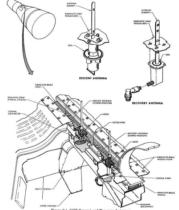
The antenna element consists of two one-half inch wide gold plated steel blades bolted together at two places. The uhf descent antenna is approximately 16inches long. The uhf recovery antenna is approximately 18 inches long.
Mechanical Characteristics: For rigidity, the
antenna element is shaped in a
0.5 inch wide src having a radius of 1.5 inches. The two laminations of
steel
blades, compounding a single antenna element, are rigidly secured at the
lower
half of the antenna. To allow a slight displacement of the two
laminations with
respect to each other during stowage and deployment, two nuts and bolts
placed
through elongated holes secure the two laminations together at the upper
half of
the antenna element.
The antennas are bent towards the small end of the spacecraft for stowage and are held in place by a retaining strap. The strap is broken when the Landing System shifts from single point to two point suspension, allowing the antennas to extend.
Each of the two antennas have a radiation pattern which is identical to that of a quarter wave stub.
The uhf stub antenna (Figure below) allows simultaneous transmission of the real-time and stand-by telemetry transmitters, transmission and reception for the uhf voice transmitter/receivers, and reception for DCS receiver number 2. The antenna may be used from pre-launch until separation of the R & R section during re-entry, but is normally used from pre-launch to insertion and from re-entry preparation to R & R section separation.
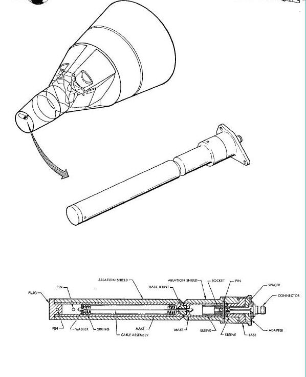
Physical Characteristics: The uhf stub antenna, physically constructed as illustrated in the Figure above, is mounted in the nose of the R & R section. The antenna protrudes forward from the R & R section and is covered by a nose fairing during the boost phase of the mission. The antenna consists of a mast and base which weighs approximately 1.1 pounds. The mast is constructed of 3/4 inch cobalt steel, machined to tubular form, and covered by a Teflon ablation shield for protection during re-entry. The antenna is approximately 13.5 inches long including the connector, and 1.25 inches in diameter over the ablation material. The mast consists of two sections. The front section is mounted on a cobalt steel ball Joint and retained to the rear section by a spring loaded cable. Electrical contact between the mast sections is made through the ball Joint and the spring loaded cable assembly. The ball Joint allows the front section of mast to be deflected to approximately 90 degrees in any direction around the antenna axis. The spring of the cable assembly is pre-loaded to approximately 45 pounds to cause the front section, when deflected, to return to the erected position.
The rf connector is press fitted into a socket and makes contact to the mast through the socket and sleeve, which are the same material as the mast. The shell of the rf connector is mounted to the base which is isolated from the mast by a Teflon spacer and sleeve.
Mechanical Characteristics: The uhf stub is a quarter wave length antenna. The radiating length of the antenna is approximately 11.2 inches.
Purpose: Two identical uhf whip antennas (Figure below) supply the required uhf transmission and reception facilities during orbit. One of the uhf antennas is located on the adapter equipment section and serves the DCS receiver number 1, and the acquisition aid beacon or delayed-time telemetry transmitter. The second uhf antenna, mounted on the adapter retrograde section, serves the realtime and standby telemetry transmitters, the uhf voice transmitter/receivers, and DCS receiver number 2.
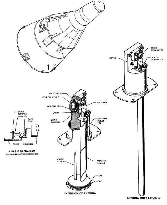
Physical Characteristics: The uhf whip antenna is self extendable and requires no power other than that required for initial release. The antenna element is a tubular device made from a 2 inch wide beryllium copper strip processed in the form of a tube. The antenna, when fully extended, forms an element that is approximately 12 inches long and 1/2 inch in diameter. During stowage, the tube is opened flat, wound inside of a retaining drum, and latched in position. Upon release of the latch by a solenoid, the extension of the antenna depends entirely on the energy stored in the rolled strip material. This energy is sufficient to erect the antenna at a rate of 5 feet/second into its tubular form. In the stored condition, the antenna is flush with the outer skin of the spacecraft.
Mechanical Characteristics: The antenna element is retained inside the housing by a metal lid. A metal post Is attached to the lid and passes through the center of the coiled antenna. The bottom of the post is grooved to accept a forked latch which holds the catch post assembly firmly in position prior to release. The forked latch is attached to a miniature pull-solenoid which is spring loaded in the extended position to ensure that launch shock and vibration loads will not cause inadvertent antenna extension. When a voltage from the Sequence System is applied to the antenna solenoid, the latch will be withdrawn allowing the antenna cap to eject and the antenna to extend. As the catch post assembly is ejected, a microswitch in series with the solenoid coil opens the circuit to the coil to prevent further current drain from the power source. The two antennas are Jettisoned with the corresponding adapter section.
Purpose: The hf whip antennas provide transmission and reception for the hf voice transmitter/receiver during the orbital and postlanding phases of the mission.
Physical Characteristics : The hf whip antennas are physically constructed as illustrated in the Figure Below. The recovery hf whip antenna is mounted on the small pressure bulkhead, outside the pressurized area of the spacecraft re-entry module. The other hf whip antenna is located on the adapter retrograde section. The antenna mechanism housing, approximately 6.25 inches wide and 22.4 inches high, completely encloses all parts of the antenna including storage space for the antenna elements.
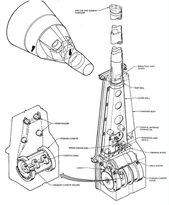
The recovery hf whip antenna contains six
elements which, when fully extended, comprise a single antenna mast
approximately 13 feet 3 inches long. The adapter hf whip antenna
contains three elements which, when fully extended t comprise a single
antenna mast approximately 16 feet long on spacecraft 5 and 6, and
approximately 13 feet long on later spacecraft. The mast is one inch in
diameter on all spacecraft. Two connectors, supported by the antenna
body, provide a means of applying power and connecting the antenna to
the rf connector on the hf voice transmitter/receiver. The recovery hf
whip antenna weighs approximately 9.0 pounds.
The 16-foot version of the adapter hf whip antenna weighs approximately
7.5 pounds and the 13-foot version 6.0 pounds. The main supporting
structure of the antenna mechanism housing is the antenna body
consisting of a thin fiberglass shell.
The outer shell is made in two sections which mate together and form a completely sealed envelope around all moving parts. The antenna mast elements are heat treated stainless steel strips and are stored in a dc motor driven cassette.
Mechanical Characteristics : The strip material comprising the antenna elements is heat treated into a material circular section in such a manner that the edges of the material overlap approximately 180 degrees. When the antenna is retracted, the tubular elements are continuously transformed by guide rollers into a flattened condition, and stored in a strained manner in a cassette. Extension and retraction of the antenna is accomplished by a motor which, by means of a chain, drives the storage cassette core. Because of the natural physical shape of the antenna elements, the antenna has a tendency to self-extend; thus giving an extension time of approximately 25 seconds. Retraction time is approximately 40 seconds. The antenna is stopped within its desired limits by two microswitches, one for extension and one for retraction, which automatically cut the power applied to the motor at the time of extreme limits of the antenna are reached.
The rf connection to the antenna is obtained by a wiper arm sliding on the cassette core drive shaft.
On spacecraft 53 the hf whip antennas are operated as follows : Spacecraft control bus voltage is supplied through the WHIP ANTENNAS HF circuit breaker to the HF ANT switch. The adapter hf whip antenna is extended during orbit by positioning the HF ANT switch to EXT. The adapter hf whip antenna is not retracted during orbit, but is Jettisoned in the extended position with the retrograde section. After landing, the recovery bf whip antenna is extended by positioning the HF ANT switch to PST LDG, and is retracted by positioning the HF switch to EXT.
On spacecraft 6 through 12, extension of the hf whip antenna is controlled through the HF ANT switch and LANDING switch. The hf antennas are operated as follows: Spacecraft control bus voltage is supplied through the WHIP ANTENNAS - HF circuit breaker to the HF ART switch, which has momentary type contacts. During orbit, the LANDING switch is in the SAFE position and adapter hf whip antenna can be extended or retracted by holding the LANDING switch in the EXT or RET position respectively. During re-entry, the LANDING switch is placed in the ARM position. After landing, the recovery hf whip antenna can be extended or retracted by holding the HF ANT switch in the EXT or RET position respectively. The HF ANT switch should be held in the EXT position for approximately one minute for full extension of the antennas, and in the SET position for approximately 1.5 minutes for full retraction.
Purpose: The C-band Annular slot antenna (Figure below) serves the adapter C-band radar beacon and is normally used during stabilized flight.
Mechanical Characteristics: The antenna radiation pattern is identical to that of a quarter wave stub on a ground plane. The antenna is used for both reception and transmission of the adapter C-Band radar beacon during the orbital phase of the mission. The antenna is Jettisoned with the equipment section of the adapter.
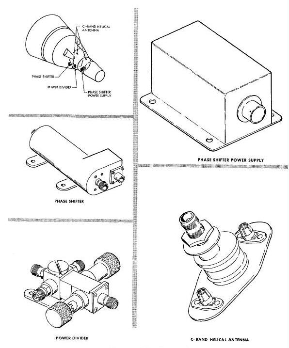
Purpose: The C-Band antenna system, consisting of a power divider, a phase shifter, and three helical antennas, provides transmission and reception capability for the re-entry C-band radar beacon. The power divider supplies equal transmission power to the three helical antennas. A phase shifter is in series with one of the antennas to compensate for areas of low or no radiation coverage between lobes of the three individual radiation patterns. A phase shifter power supply supplies the phase shifter with 26 vac 453 cps power. The antenna system gives the circular radiation pattern around the spacecraft longitudinal axis required for ascent, descent and roll spacecraft attitudes.
Physical Characteristics: The power divider, phase shifter, phase shifter power supply, and helical antennas are shown in this Figure . The power divider, phase shifter, and phase shifter power supply are mounted on the small pressure bulkhead, outside the pressurized area of the spacecraft. The power divider measures approximately 3.86 inches over the connectors, 4.0 inches over the tuning knobs and weighs approximately 6.5 ounces. The phase shifter is approximately 5.8 inches long, 2.84 inches wide at the large end, 1.4 inches high, has a diameter at the small end of about 1.5 inches, and weighs approximately 12 ounces. The phase shifter power supply measures approximately 1.5 inches wide, 1.75 inches high, 3.5 inches long over the connector and weighs approximately 8 ounces.
The three C-band helical antennas are mounted flush with the outside skin of the spacecraft and spaced approximately 120 degrees apart. Each antenna unit is approximately 3.4 inches long, 1.8 inches wide, has a depth of 2.21 inches over the connector and weighs approximately 3.5 ounces.
Electrical Characteristics : The power divider, phase shifter, and helical antennas comprise an antenna system that satisfies the transmission and reception requirements for the re-entry C-band radar beacon during the launch and re-entry phases of the mission.
The power divider is basically a cavity type power splitter. During beacon transmission, power is delivered to the power divider where it is divided equally among the C-band helical antennas. The power divider compensates for loss of power due to the phase shifter in series with the right antenna. The power divider contains a double stub tuner to compensate for mismatch between the re-entry C-band beacon, the C-band helical antennas, and the phase shifter. Tuning is accomplished by means of a self-locking tuning shell located underneath each tuning stub cap.
The phase shifter has its own ac power supply.
The input to the phase shifter, is half wave rectified and applied
across a coil wound around a ferrite material. Due to the
characteristics of the ferrite material, the rf signal from the power
divider is delayed 0 to 180 degrees + 20 degrees at the rate of 453
cycles per second. The changing phase shift of the rf power on one of
the C-band helical
antennas with respect to the other two, shifts the lobe of that antenna
by approximately + 45 degrees; thus giving the effect of an almost ideal
circular radiation pattern around the longitudinal axis of the
spacecraft. The combination of the three antenna elements gives a
radiation pattern which extends in all directions except forward and aft
of the spacecraft.
The phase shifter power supply is a dc-ac inverter which supplies a nominal 26 vac, 453 cps power to operate the phase shifter. The power supply is a hermetically sealed solid-state unit consisting of a voltage regulator single-stage oscillator, buffer stage, and a push-pull output stage vith transformer coupled output. The power supply provides a minimum output of 21 volts rms at 453 + 17 cps with an input voltage range from 20 to 30 vdc. Input voltage is applied from the spacecraft main bus via the BEACON-C circuit breaker, C-RNTY BEACON C0NTRCL switch and the RNTY position of the ANT 8EL switch. Maximum input current is 370 milliamperes.
Multiplexers (UHF Diplexer and UHF Quadriplexer)
Purpose: The uhf diplexer provides isolation between DCS receiver number 1, and the acquisition aid beacon or the delayed-time telemetry transmitter operating into a common antenna. The uhf quadrlplexer provides isolation between the standby telemetry transmitter, the real-time telemetry transmitter, a uhf voice transmitter/receiver and DCS receiver number 2 operating into a common antenna via coaxial switches.
Physical Characteristics: The physical representation and approximate location of the uhf diplexer and the uhf quadriplexer is shown in the Figure below. The diplexer is located on the electronic module of the adapter equipment section. The quadriplexer is located forward of the small pressurized bulkhead outside the pressurized area of the cabin.
UHF Diplexer/ UHF Quadplexer Diagram
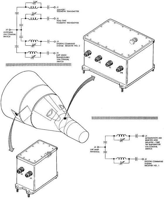
The diplexer is approximately 4. 5 inches wide, 4 inches high and 2.7 inches deep; contains two input and one output connectors, and weighs approximately 1.25 pounds. The uhf quadriplexer is approximately 5.75 inches wide, 5.5 inches deep, and 4.1 inches high; weighs approximately 2.75 pounds, and has four input and one output connectors.
Electrical Characteristics: Figure above shows the schematic of the uhf diplexer and the uhf quadriplexer. Each channel consists of a high Q cavity, tuned to the corresponding operating frequency. All channels are isolated from each other without appreciably attenuating the rf signals passing through it. Each channel can be re-tuned if the assigned operating frequency is chased. The diplexer isolates DCS receiver number 1, and the acquisition aid beacon or the delayed-time telemetry transmitter, depending upon the position of coaxial switch number 2. The diplexer operates into the hf whip antenna on the adapter equipment section.
The uhf quadriplexer isolates the real-time telemetry transmitter, the stand-by telemetry transmitter, one of the two uhf voice transmitter/receivers, and DCS receiver number 2. The quadriplexer operates into one of the following three uhf antennas, depending on the position of the coaxial switches in series with the antennas: uhf stub antenna, uhf descent antenna, or the uhf whip antenna on the adapter retrograde section.
Purpose: Five coaxial switches are used to perform the following functions : (1) select the acquisition aid beacon or the delayed-time telemetry transmitter output as the input to the diplexer; (2) select one of the two uhf voice transmitter/receiver outputs as the input to the quadriplexer; (3) connect the hf voice transmitter/receiver to the adapter hf whip antenna on the retrograde section, or to the recovery hf whip antenna on the re-entry module; (4) connect the output of the quadriplexer to the uhf descent antenna or through coaxial switch 5 to the uhf stub or the retrograde adapter uhf whip antenna.
Physical Characteristics: The physical construction and approximate location of the coaxial switches is shown in the Figure below.
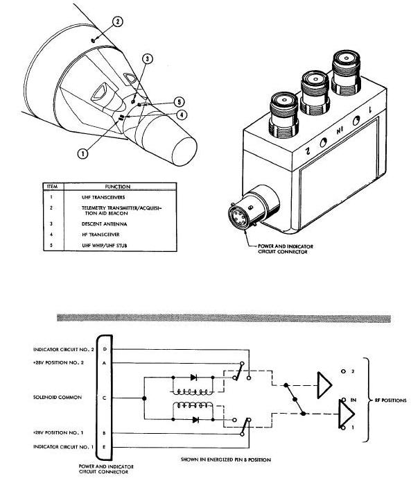
The location of the switches is as follows:
Coaxial switch 1: approximately five inches from the small end of the cabin, in the fourth quadrant.
Coaxial switch 2: approximately 10 inches from the forward (small) end of the adapter equipment section, in the third quadrant.
Coaxial switch 3: approximately 10 inches from the small end of the cabin, in the third quadrant.
Coaxial switch 4: locaed adjacent to coaxial switch 1
Coaxial switch 5: approximately 7 inches fram the small end of the cabin, in the third quadrant.
Each switch contains a power connector, an input connector, two output connectors, and weighs approximately 0.5 pounds. The dimensions of each switch are approximately 2.65 inches long, 1.82 inches high, and 1 inch wide.
Electrical Characteristics: The
five coaxial switches are identical and may be used interchangeably.
Basically, the coaxial switches supply single pole double throw
switching action as illustrated in
this Figure.
The switch, having a 20 millisecond maximum operation time, operates on
3 amperes at 28 vdc and uses a latching solenoid break-before-make
switching action. The coaxial switches are
designed to operate 15 mc to 500 mc, and from 5500 mc to 5900 mc.
Pins D and E of each switch are brought out to AGE test points to permit
monitoring of the switch positions prior to lift-off. Pins A and B of
each switch are utilized to accomplish the switching action.
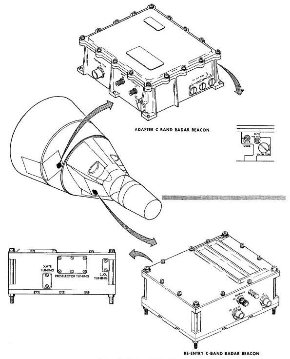
Purpose : The re-entry C-band radar beacon provides tracking capability of the spacecraft from lift-off to insertion and from retrograde to landing. The re-entry C-band beacon may be used during roll maneuvers or in the event of adapter C-band beacon failure.
Physical Characteristics : The re-entry C-band radar beacon is a sealed unit which measures approximately 7.64 x 6.14 x 3.02 inches and weighs about 8.3 pounds. As shown in Figure 9-11, the beacon has power, antenna, and test connectors. Located on the rear of the beacon are various adjustments for transmitter, preselector, and local oscillator tuning. Solid-state modular circuitry is used throughout the beacon with the exception of the transmitter magnetron and the local oscillator. The beacon is mounted on the right forward equipment bay, and uses the C-band antenna system for reception and transmission.
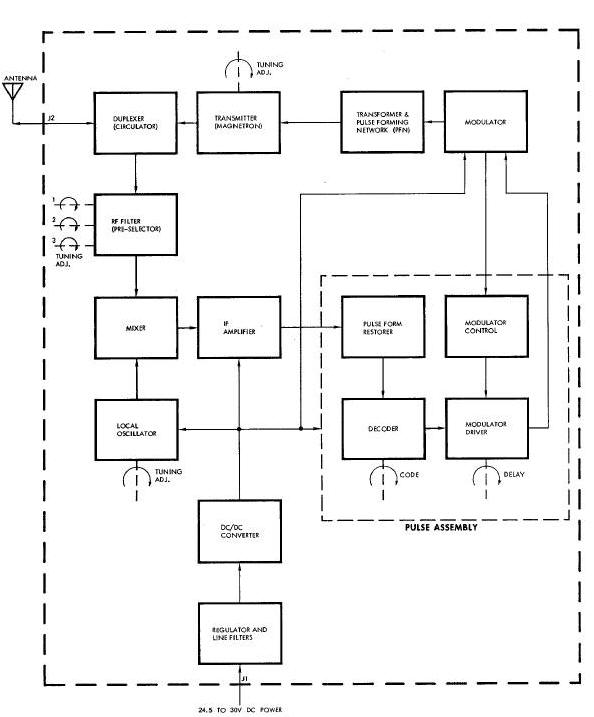
Electrical Characteristics: The re-entry C-band radar beacon is a transponder which upon reception of a properly coded interrogation signal from a ground radar tracking station, transmits a pulse modulated signal back to the tracking station. By measuring the elapsed time between transmission and reception at the tracking stations, and compensating for the time delay of the beacon, the position of the spacecraft can be determined. The block diagram of the beacon is shown in the Figure below
Re-Entry C-Band Radar Beacon Block Diagram

The signal arriving at the antenna is routed through the directional coupler to one half of a dual ferrite circulator. The ferrite circulator isolates the transmitter from the receiver, allowing a single antenna system to be used for both reception and transmission. The beacon utilizes a superhetrodyne receiver which is tunable, by means of a three stage preselector, over a range of 5600 mc to 5800 mc. The assigned receiver center frequency is 5690 me.
The output of the preselector is combined with the local oscillator frequency in the crystal mixer to produce an output intermediate frequency of 80 mc. The local oscillator is of the metal-ceramic triode cavity type. The mixer contains a ferrite circulator for isolation between the local oscillator, mixer and preselector. The output of the mixer is amplified by three tuned intermediate frequency amplifier stages, followed by a video detector and a video preamplifier. Additional amplification is obtained by a pulse amplifier whose output is supplied to the decoder. The purpose of the decoder is to initiate triggering of the transmitter after a correctly coded signal has been received. The system delay, in conjunction with the delay variation correction circuitry, provides for a constant fixed delay used in determining the exact position of the spacecraft. The beacon incorporates a cw immunity circuit that prevents the transmitter from being triggered by random noise. The noise level is reduced below the triggering level of the transmitter by controlling the gain of the pulse amplifier. The transmitter uses a magnetron and provides a one kilowatt peak pulse modulated signal at a frequency of 5765 mc to the power divider. The beacon is powered by a dc-dc converter employing a magnetic amplifier and silicon controlled rectifiers. The converter provides voltage regulation for input voltage variations between 18 and 32.5 vdc. The input to the converter is filtered by a pl-type filter to minimize any line voltage disturbances.
Purpose: The adapter C-band radar beacon provides tracking capability of the spacecraft during the orbital phase of the mission and is jettisoned with the adapter equipment section.
Physical Characteristics : The
adapter C-band beacon is a sealed unit and measures approximately 9.34 x
8.03 x 3.26 inches. As shown in Figure 9-11, the adapter beacon has a
power and test connector, an antenna connector, and a crystal current
test point connector. The beacon contains external adjustments for local
oscillator, preselector (rf filter), and transmitter tuning; switches
for selecting the desired interrogation code, and one of two preset
transponder fixed delay times. These adjustments and switches are
accessible by removing pressure sealing screws. The beacon employs
solid-state circuitry, except for the transmitter magnetron
and receiver local oscillator. The adapter beacon is located on the
electronic module of the adapter equipment section and uses the C-band
annular slot antenna for reception and transmission.
Electrical Characteristics: The adapter C-band radar beacon is a transponder, which employs the same basic operating principles as the re-entry C-band beacon to provide spacecraft location data upon receipt of a properly coded interrogation signal. A block diagram of the adapter C-band beacon is shown in Figure below.
Adapter C-Band Radar Beacon Block Diagram
The interrogation signal is fed from the antenna to the duplexer. The duplexer is a ferrite circulator which couples the received signal to the rf filter preselector and also isolates the receiver from the transmitter to permit use of a common antenna for reception and transmission. The superhetrodyne receiver frequency is tunable from 5395 mc to 5905 mc. The assigned operating center frequency is 5690 mc and is selected by adjustment of the rf filter.
The rf filter is a three-stage preselector, employing three separately tuned coaxial resonator cavities to provide adequate rf selectivity and to protect the mixer crystal from damage due to transmitter power reflected by the antenna. The output of the preselector is combined with the local oscillator output in the mixer stage to provide a 60 mc output to the intermediate frequency amplifier.
The mixer consists of a coaxial directional coupler and a mixer crystal. The directional coupler isolates the local oscillator output from the antenna and directs it to the mixer crystal. The local oscillator is a re-entrant cavity type employing a planar triode to generate the cw signal required to operate the mixer.
The intermediate frequency amplifier is a high
gain amplifier composed of an input stage, five amplifier stages, and a
video amplifier. The amplified video output is fed to the pulse form
restorer circuits which prevent a ranging error due to variations in
receiver input signal levels, and also provides a standard amplitude
pulse to the decoder for each input signal exceeding its triggering
threshold.
The decoder determines when a correctly coded signal is received and
supplies an output to the modulator driver. The type code to he accepted
is selected by the CODE switch. Single pulse, two pulse or three pulse
codes may be selected. The modulator driver and control circuits
initiate and control triggering of the transmitter modulator. The
modulator driver supplies two fixed values of overall system delay. The
desired delay is selected by the position of the DLY switch. An
alternate value of maximum delay is available by removing an internal
Jumper lead. The modulator control furnishes the trigger and turn-off
pulse for the modulator and limits modulator triggers to prevent the
magnetron duty cycle from being exceeded, regardless of the
interrogating signle frequency. The modulator circuit employs silicon
controlled rectifiers which function similar to a thyratron, but require
a much shorter recovery time.
The associated modulator Pulse Forming Network (PFN) and transformer provide the necessary pulse to drive the transmitter magnetron. The desired pulse width is selected by the internal connections made to the PFN. The transmitter magnetron frequency is tunable from 5400 mc to 5900 mc. The assigned transmitter center frequency is 5765 inc. A minimum of 500 watts peak pulse power is supplied to the antenna under all conditions of rated operation.
The transponder power supply consists of input line filters, a series regulator, and a dc-dc converter. The power supply furnishes the required regulated output voltages with the regulated input voltage between 21 and 30 vdc. The converter employs a multivibrator a full wave rectifier circuits.
Purposes Unlike the C-band beacons that supply accurate tracking data, the acquisition aid beacon is merely a transmitter used to determine when the spacecraft comes within range of a ground tracking station. When the spacecraft comes within the range of a ground tracking station 3 the acquisition aid beacon is disabled and remains off until the spacecraft is again out of range.
Physical Characteristics: The acquisition aid beacon, shown in Figure Below, is cylindrical, having a diameter of approximately 2.6 inches, and a height of approximately 3.5 inches. The acquisition aid beacon is located as shown in Figure Below. The beacon contains a power connector, a coaxial antenna connector and weighs approximately 17 ounces.
Acquisition Aid and UHF Recovery Beacons Diagram

Electrical Characteristics: The acquisition aid beacon consists of a transmitter, de-de voltage regulator, and a low pass output filter.
The transmitter is an all transistorized unit, containing a push-pull output stage to obtain a minimum output of 200 milliwatts at a frequency of 246.3 mc. The transmitter frequency is derived by taking the basic frequency of an oscillator and multiplying it through a series of tripler and doubler stages.
The transmitter is powered by a dc-dc voltage regulator. The regulator is completely transistorized and supplies a regulated output voltage of 28 vdc. To reduce the probability of obtaining a spurious output signal, a band pass filter is placed in the output circuit.
Purpose: The uhf recovery beacon, operating on the international distress frequency of 243 mc, serves as a recovery aid by providing information regarding location of the spacecraft.
Physical Characteristics: The uhf recovery beacon and its approximate location is shown in Figure above. The beacon is mounted on the aft right equipment bay of the spacecraft re-entry module. The beacon is approximately 9.0 inches long, 4.0 inches wide, 2.5 inches high, and weighs 3.9 pounds maximum. The beacon contains one multlpin power connector and one coaxial connector.
Electrical Characteristics. The uhf recovery beacon consists of a spike eliminator, a regulator, a dc-dc converter, a pulse coder, a modulator, and a transmitter.
Spacecraft main bus voltage is fed to the switching type regulator through the spike eliminator filter. The voltage regulator provides a dc regulated output voltage of 12 vdc to the dc-dc converter, the transmitter tube filaments, and the pulse coder.
The dc-dc converter is a solid-state device providing two high voltage outputs to the transmitter and modulator. The pulse coder, a solid-state device, operates with the modulator to apply correctly coded high voltage pulses to the transmitter for plate modulation of the power amplifiers.
The transmitter consists of an oscillator stage, a doubler stage, and a power amplifier. The transmitter power amplifier provides a uhf pulse coded output having a peak power of at least 50 watts to the uhf recovery antenna. An external rf band-pass filter is installed between the transmitter output and the antenna to reduce spurious rf radiations, especially at the uhf voice transmitter frequencies.
Purpose: The Voice Control Center contains switches and controls for selecting the type of voice communication and the desired operating mode. The VCC also contains microphone and headset amplifiers, an alarm tone generator, and voice actuated transmitter keying circuitry.
Physical Characteristics: The VCC and its approximate location is shown in Figure below.
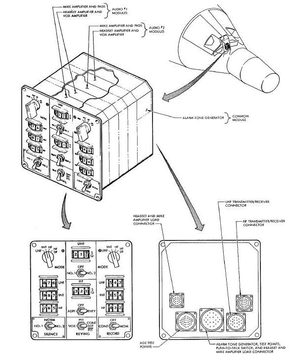
The VCC is mounted in the center instrument panel of the spacecraft cabin. The VCC is modular constructed, approximately 6.4 inches wide, 6.4 inches high, 5.5 inches deep, and weighs approximately 6.5 pounds.
Five connectors located on the rear of the unit provide connection to the other voice communication system components and test connectors. The function of each connector is listed on Figure above.
The switches and controls of the VCC are located on the front panel. The number 1 and number 2 audio MODE switches are for selection of UHF, INT, HF, or HF/DF transmission. Below the MODE switches are three thumb-wheel-type multidetent volume controls, one for each of the above mentioned modes.
In the center is the KEYING switch, a HF select switch, a UHF select switch, and thumb-wheel-type squelch controls for uhf and hf circuitry. The KEYING switch provides for selection of PTT, VOX, or CONT INT/PTT for the voice transmitters. The UHF and HF select switches provide capability of selecting the desired transmitter/receiver. The ADPT position of the HF select switch is not used.
The record switch, lower right, permits recordings to be made in any mode of operation. Continuous (CONT) or Momentary (MOM) recording can be selected.
The SILENCE switch, lower left, is to permit uninterrupted sleep during extended spacecraft missions. The N0. 1 position allows reception for both pilots. The NO. 1 position removes power from the command pilot's headset amplifiers and the NO. 2 position removes power from the pilot's headset amplifiers; thus, making reception impossible.
Electrical Characteristics: The VCC contains two headset and two microphone amplifiers for each of the audio channels.
The Figure below shows a functional block diagram of the VCC. An audio signal, from the microphone in the helmets or lightweight headsets, is amplified by two microphone amplifiers and then applied to the MODE switch.
Voice Control Center Functional Block Diagram
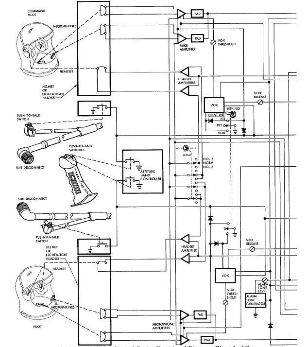
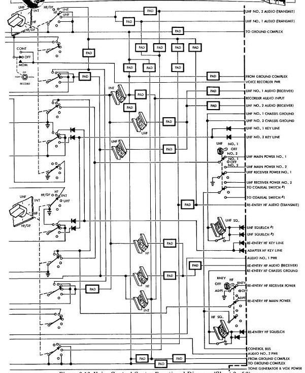
With the MODE switch in the HF position, the output of the microphone amplifiers is applied to the hf transmitter. When the MODE switch is in the INT position, the output of the microphone is applied to the four headset amplifiers, via the two INT volume controls. With the MODE switch in the UHF position, the output of the microphone amplifiers is applied to the UHF transmitters. The UHF switch selects uhf transmitter number 1 or number 2 and also operates coaxial switch 1 to connect the selected transmitter output to the uhf quadriplexer. The desired keying mode is selected by a common Keying switch. Three methods may be selected to key the voice transmitters. VOX position enables keying of the selected transmitter at the instant the microphone has an output signal. The PTT position enables keying of the transmitter when either push-to-talk switch, on the suit disconnect cables of the attitude control handle, is depressed. The CONT INT/PTT position gives continuous intercommunication between the crew and push-to-talk keying for transmission from the spacecraft to the ground station.
The VCC also controls the power supplies of the transmitter/receivers by means of ground switching. With the MODE switch in a position other than HF and the HF select switch in the RNTY position, a ground is supplied to the hf transmitter/receiver auxiliary power supply to power the hf receiver.
With the HF select switch in RNTY and the MODE switch in the HF position, a ground is supplied to the hf transmitter/receiver main power supply to power the hf receiver and transmitter. The uhf circuitry operates on the same principle as the hf. The UHF select switch supplies power ground for the selected receiver.
The MODE switch (UHF position) together with the UHF select switch, supplies a power return for the uhf transmitter and receiver.
The HF/DF position of the MODE switch is used for direction finding purposes. With the MODE switch in HF/DF and the HF select in the RNTY position, the hf transmitter is modulated by a 1,000 cps tone which is utilized to determine spacecraft location.
UHF Voice Transmitter/Receivers
Purpose: Two uhf voice transmitter/receivers are provided for redundant line-of-sight voice communication between the spacecraft and the ground.
Physical Characteristics: The uhf voice transmitter/receivers and their approximate location is shown in Figure Below. Both transmitter/receivers are identical and are mounted side by side in the forward right equipment bay of the re-entry module.
UHF Voice Transmitter Receiver Diagram
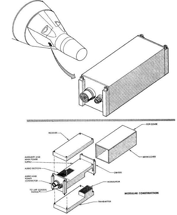
Each transmitter/receiver is a modular constructed, hermetically sealed unit approximately 7.7 inches long, 2.8 inches wide, 2.4 inches deep and weighs approximately 3.0 pounds. Each unit has a multipin audio and power connector, and a coaxial connector.
Electrical Characteristics: The uhf voice transmitter/receiver consists of a transmitter, receiver, and power supply.
The transmitter consists of a crystal controlled oscillator, two rf amplifiers, a driver, and a push-pull power amplifier. All stages except the driver and power amplifier are transistorized. The transmitter is fixed-tuned at 296.8 mc and is capable of producing an rf power output of 3.0 watts into a 50 ohm resistive load. The transmitter is amplitude modulated (am) by a transistorized modulator stage.
The am superhetrodyne receiver is fully transistorized, is fixed-tuned at a frequency of 296.8 mc, and contains a squelch circuit for noise limiting. The squelch threshold is manually controlled. An automatic volume control stage is also incorporated to provide a constant audio output with input signal variations.
The uhf voice transmitter/receiver is powered by two dc-dc converters comprising an auxiliary and a main power supply. Operating power for the two power supplies is limited by two circuit breakers located on the left switch/circuit breaker panel. One circuit breaker is provided for each unit. Actuation of the power supplies is accomplished by ground return switching through the Voice Control Center. If the UHF select switch is in the NO. 1 or NO. 2 position and the MODE switch is in a position other than UHF, a ground is supplied to the auxiliary power supply only, placing the transmitter/receiver into a receive condition. With the MODE switch in the UHF position, a ground is supplied to the main power supply, placing the selected uhf voice transmitter/receiver into a receive and transmit condition.
It should be noted that when the uhf transmitter is keyed, the uhf receiver is disabled and uhf voice transmissions from the ground station can not be received.
Purpose: The hf voice transmitter/receiver is provided to enable beyond the line-of-sight voice communication between the spacecraft and the ground.
Physical Characteristics: The Figure below shows the modular construction and approximate location of the hf voice transmitter/receiver in the forward right equipment bay of the re-entry module. The unit weighs approximately 62 ounces, is approximately 8.5 inches long, 3.3 inches wide, and 2.9 inches deep. One multipin audio connector and one rf connector are provided.
HF Voice Transmitter/Receiver Diagram
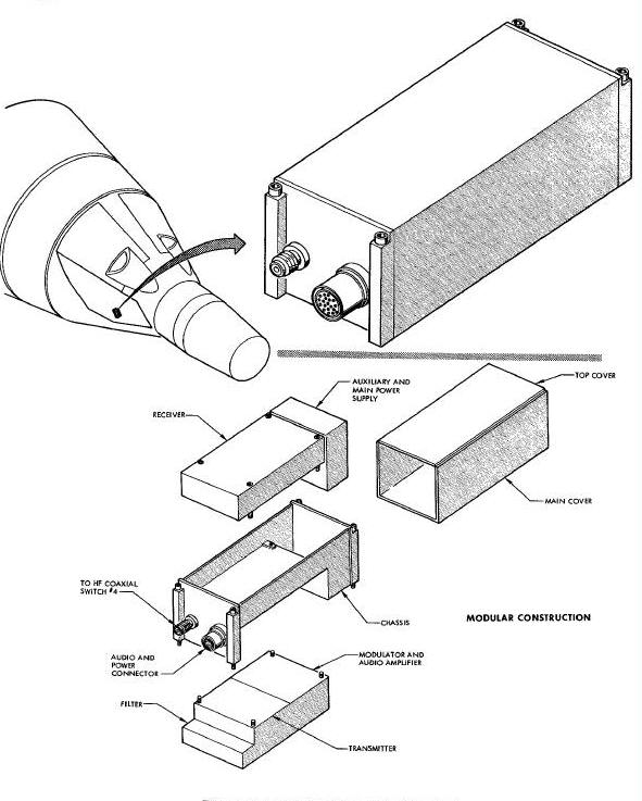
Electrical Characteristics: Basically, the hf voice transmitter/receiver is electrically identical to the uhf transmitter/receiver except for the operating frequency and power output. The hf transmitter and receiver are fixed tuned to a frequency of 15.016 mc and the hf transmitter provides an rf power output of 5 watts.
Actuation of the hf receiver and transmitter is accomplished through the VCC. If the HF select switch is in RNTY and the MODE switch is in a position other than HF, the hf transmitter/receiver is in a receive condition. With the MODE switch in the HF position, the hf transmitter/receiver is placed in a receive and transmit condition.
When the hf transmitter is keyed, the hf receiver is disabled.
Purpose: The voice tape recorder is provided so recordings can be made during the spacecraft mission.
Physical Characteristics: The physical construction and approximate location of the voice tape recorder is shown in the Figure below. The voice tape recorder is located inside the cabin in a vertical position between the pilot's seat and the right-hand side wall on spacecraft 5 and 6. On spacecraft 8 through 12 the recorder is located on the left-hand side wall aft of the abort handle.
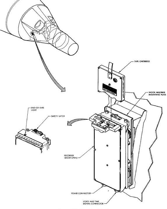
The voice tape recorder assembly consists of the recorder, tape cartridge, and shock absorber mounting plate and is supplied as GFE equipment. The recorder is approximately 6.25 inches long, 2.87 inches wide, one inch thick, and weighs 30 ounces maximum without the tape cartridge. The shock absorber mounting plate is approximately 6.3 inches long, three inches wide, and weighs 20 ounces maximum. The tape cartridge is approximately 2.25 inches square, 3/8 inch thick and weighs two ounces.
The recorder contains a power connector and a signal connector located on the end. as shown in this Figure. The recorder is retained in the shock mount by guides and two allen-head bolts for easy removal. The door contains a red plastic lens so that light from the end-of-tape bulb is visible. A safety latch prevents accidental opening of the door. The door is opened by pressing down on the latch and sliding it sideways. When the latch is released, the spring loaded hinge causes the door to open, exposing the cartridge tab. Flat pressure springs on the door hold the inserted cartridge in place and maintains tape contact with the recorder head and end-of-tape contact.
The tape cartridge is guided into the recorder by step rails on each side of the cartridge. When the recorder door is opened, a heavy tab on the cartridge springs up to provide easy removal. The cartridge contains approximately 180 feet of magnetic tape, a supply reel, take-up reel, and associated gears and clutches.
Electrical Specifications: The recorder is a two-channel transistorized unit consisting of the cartridge hold-down mechanism, voltage regulator, voice amplifier, time signal amplifier, bias oscillator, motor drive circuit synchronous drive motor, speed reduction unit, capstan, magnetic record head, and end-of-tape circuit. When the tape cartridge is inserted and secured in the tape recorder, the pressure roller in the cartridge contacts the capstan and the tape is pressed against the record head and the end-of-tape contact.
The voice tape recorder is energized by spacecraft main bus power applied through the TONE VOX circuit breaker and the CONT or MCN position of the RECORD switch on the VCC. The voltage regulator supplies 15 vdc to the motor drive circuits bias oscillator and amplifiers. With the VCC and recorder energized, voice signals from the microphones are applied through microphone amplifiers in the VCC to the recorder voice amplifier. The voice signal is amplified and applied to the lower record head for recording on the magnetic tape. The time channel receives a digital timing signal from a time correlation buffer in the TRS. The timing signal is amplified by the recorder time signal amplifier and applied to the upper record head for recording on the magnetic tape. Simultaneously with the voice or timing signal, a 20 kc bias current from the bias oscillator is applied to the recorder heads to make a linear recording.
The motor drive circuit consists of a 133 cps oscillator, a driver and push-pull output stage used to drive the synchronous motor. Phase-shift capacitors are connected to one motor winding for self-starting. The motor speed of 8000 rpm is reduced through the speed reduction unit to a capstan speed of 122 rpm.
The end-of-tape circuit is energized by
conductive foil on the tape contacting the recorder head and end-of-tape
contact, causing the end-of-tape light to illuminate. The end-of-tape
light will illuminate for two seconds when two minutes of recording time
remains on the tape. The light will remain on when the end-of-tape is
reached. Recordings cannot be made when the light is illuminated.
The pilot may remove the used tape cartridge, insert another cartridge
and continue recording. Each cartridge provides approximately one hour
of recording. The tape speed is approximately 0.6 inches per second.
Purpose: The three telemetry transmitters provide a radio frequency (rf) link from the spacecraft to ground communication facilities for transmission of various data obtained by the Instrumentation System.
Physical Characteristics: The
three telemetry transmitters are identical except for the operating
frequency. The physical construction and approximate location of the
transmitters in the spacecraft is shown in the Figure below. The
transmitters
are approximately 2.75 inches high, 2.25 inches wide, 6.5 inches long,
and weigh approximately 41 ounces.
Telemetry Transmitters Diagram
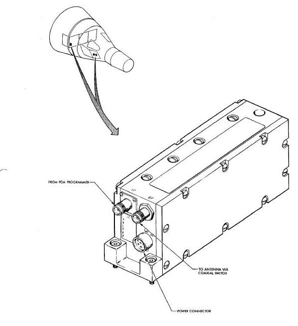
Each transmitter contains a dc power connector,
an rf output power connector, and a video connector. Two of the
transmitters are
located in the right forward equipment bay of the re-entry module, the
third is located on the electronic module in the adapter equipment
section.
Electrical Characteristics: The three telemetry transmitters are classified by their operating frequency or by their function.
The real-time (low-frequency) telemetry transmitter operates at 230.4 mc. The delayed-time (mid-frequency) telemetry transmitter operates at a frequency of 246.3 mc. The stand-by (high-frequency) transmitter, operating at 259.7 mc, may be used for real-time or delayed-time transmission in case one of the transmitters fails.
The telemetry transmitters are solid-state fm transmitters. After a 30 second warm-up, the transmitters are capable of continuous uninterrupted operation for 500 hours. Information is transmitted to the ground in digital format by deviating the carrier frequency to the higher frequency deviation limit to transmit is 1, and to the lower deviation limit to transmit a 0.
The transmitters receive Non-Return to Zero (NRZ)
PCM pulse trains from the PCM programmer and voice tape recorder. The
real-time transmitter provides the ground monitoring stations with
current real-time data at a rate of 51.2 kilobits per second. The
delayed time transmitter provides the ground monitoring station with
data stored on the tape recorder while the spacecraft was between ground
stations. The delayed-time data is transmitted at a rate of 112.6
kilobits per second. The stand-by transmitter is used as backup for the
real-time or delayed-time transmitters in event of a failure in either
transmitter. Transmission of the real-time and delayed-time data provide
essentially full-time coverage throughout the spacecraft mission. The
transmitters can be energized by a command from the ground station via
the DCS or by controls on the instrument panel.
Each transmitter consists of five subassemblies as shown in the block diagram of the Figure below. The subassemblies are an oscillator-modulator, a times 12 (x12) multiplier and power amplifier, a bandpass output filter, a line filter and a dc-dc converter. The oscillator-modulator and the times 12 multiplier and power amplifier subassemblies contain the variable resistors, inductors, transformers and trimmer capacitors for tuning the transmitter frequency and power output. The subassembly components are point-to-point wired.
Telemetry Transmitter Block Diagram
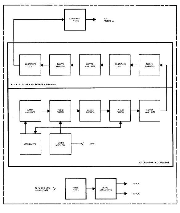
The oscillator-modulator consists of a video
amplifier, crystal controlled oscillator, phase shift networks and
buffer amplifiers. The oscillator frequency is modulated by the video
amplifier output. The phase shift networks provide impedance matching of
the crystal oscillator to improve signal linearity for large deviations
of frequency. The buffer amplifiers increase signal levels and isolate
the crystal circuit from the frequency multipliers.
The times 12 multiplier and power amplifier consists of a buffer amplifiers, times 4 multiplier, power amplifier and times 3 multiplier which increase the carrier frequency and power to the desired output values. The power amplifier develops 6 to 7 watts of power at a frequency from 75 to 80 mc into the output tripler circuit.
The bandpass filter is used to minimize spurious radiations at the output of the transmitter. The real-time, stand-by and delayed-time transmitters each contain a filter with a different frequency bandpass. The filter has a minimum 3 db bandwidth of 16 me, an impedance of 50 ohms and a vswr of less than 1.5 to 1. The rf output connector J3 is an integral part of the bandpass filter.
The line filter prevents noise on the input power bus from affecting transmitter operation and prevents transients generated within the transmitter from feeding back to the input power bus. The multipin power connector J2 is an integral part of the line filter.
The dc-dc converter is a completely encapsulated unit employing transistors, diodes and a transformer to provide regulated outputs of 30 vdc and 70 vdc from an unregulated input voltage of 18 to 30.5 vdc. The converter is a constant power input type, thus minimizing the heat dissipation caused by high voltage inputs.
FLASHING RECOVERY LIGHT AND POWER SUPPLY
Purpose: The flashing recovery light and power supply provide visual spacecraft location information.
Physical Characteristics: The below Figure shows the physical representation and approximate location of the flashing recovery light and its power supply. The light is self-extended by a torsion spring. The plug applying power to the light is kept in place by a compression spring. The recovery light will be automatically extended at the time the main parachute is Jettisoned.
Flashing Recovery Lights and Power System Diagram
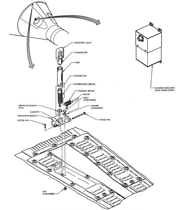
The flashing recovery light power supply is mounted in the cabin, aft of the ejection seats. The power supply is approximately 7 inches long, 4 inches wide, 3 inches deep and contains one connector. The flashing recovery light is approximately 1.25 inches wide, 0.75 inches thick, and 3.25 inches high, excluding tube and erecting mechanism. The overall length of the light and erecting mechanism is approximately 6.5 inches.
Electrical Characteristics: The recovery light is automatically extended at main parachute jettison. The extended recovery light is energized by positioning the RESC BEACON CONTROL switch to ON.
The power supply consists of a battery pack and
converter. The battery pack consists of several mercury cells to
comprise a power source of 6.75 vdc to a dc-dc converter whose output is
fed to a voltage doubler and a capacitive network. The 450 vdc output of
the voltage doubler is used to power the flashing light while the
capacitive network in conjunction with a thyratron, provides trigger
pulses to accomplish switching or flashing action of the light. The
trigger pulses occur at a rate of 15 triggers per minute.
The DCS provides a discrete command link and a digital data updating capability for the computer and TRS.
The discrete command link enables the ground to control radar tracking beacons, selection of telemetry transmitters, instrumentation data acquisition and abort indications.
The capability of digital data updating enables the mission control center to update the computer and TRS to bring about a controlled re-entry at a pre-determined point, and allows timed shutdown of equipment controlled by DCS relays.
The DCS consists of a receiver/decoder package and two relay boxes as illustrated in the DCS Decoder Figure and DCS Relay Figure, respectively. The three components are located in the electronic module of the adapter equipment section.
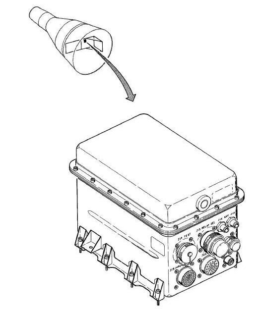
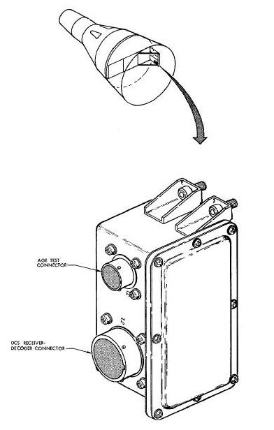
The receiver/decoder package is approximately 8 inches high, 8 inches wide, and 12 inches long. Both relay boxes are identical. Each relay box is approximately 2.25 inches wide, 5 inches high, and 3 inches deep. The combined weight of the receiver/decoder package and the two relay boxes is approximately 2B pounds. The receiver/decoder package contains two uhf receivers and a decoder while each of the two relay boxes contain eight relays.
The DCS receives Phase Shift Keyed (PSK) signals composed of a reference and an information signal. The information signal is in phase with the reference for a logical 1 and 180 degrees out of phase with the reference for a logical O; thus establishing the necessary requirements for digital data.
The DCS receives two types of digital commands: Real Time Commands (RTC) and Stored Program Commands (SPC). RTC causes relays within the DCS to be actuated. Nine of the 16 relays available for RTC are utilized to perform the following functions:
-
Select the stand-by telemetry transmitter for real-time transmission.
-
Select the stand-by telemetry transmitter for delayed-time transmission.
-
Select the real-time telemetry and acquisition aid beacon transmission.
-
Select real-time and delayed-time telemetry transmission.
-
Actuate the adapter C-band radar beacon.
-
Actuate the re-entry C-band radar beacon.
-
illuminate the abort indicators.
-
Actuate the playback tape recorder.
-
Initiate calibration voltage for the PCM programmer.
The remaining seven relays are not utilized and perform no mission function. DCS channel assignments for the nine functions listed above may be different on each spacecraft.
When the spacecraft goes out of range of the ground station, equipment controlled by DCS channels may be shutdown by a signal applied from the TRS to reset the DCS relays. This condition is known as salvo. The DCS relays in one relay box may be reset by momentarily positioning the TAPE PLY BK switch to RESET.
ihe ground station transmits a 30-bit message for SPC and a 12-bit message for RTC. Each bit consists of five sub-bits. The five sub-bits are coded to represent a logical 1 or O. The first three bits of each message designate the vehicle address. If the vehicle address is not correct, the DCS will reset itself and will not accept the message. If the vehicle address is accepted the sub-bit code will be automatically changed for the remainder of the message to reduce the probability of accepting an improper message.
The second three bits of each message designate the system address and identify the remainder of the message as being a RTC or one of the following SPC : computer update, TRS time to go (TTG) to TR, or TRS TI_ to equipment reset (Tx). If the message is a SPC, the last 24 bits will be a data word. If the SPC is a TRS TTG TO TX command, the last eight bits are ignored by the TRS. In case of a computer message, six bits of the data word contains the internal computer address and the remaining 18 contains information. Since a RTC consists of 12 bits, the six bits following the system address contain a 5-bit relay number and a 1-bit relay set-reset discrete.
The PSK modulation signals are i kc reference and a 2 kc information signal. The receiver output is the composite audio of the 1 kc and the 2 kc signals. The composite audio output is filtered to recover the 1 kc and the 2 kc signals. The phase comparator compares the 2 kc to the 1 kc signal. The output of the phase comparator is used to trigger a flip-flop to produce either a logical 1 or 0 sub-bit. The 1 kc reference signal is used to synchronize the DCS.
A block diagram of the DCS receiver/decoder is shown in the Figure below. Basically, the block diagram consists of a receiver, a decoder, and a power supply common to both sections.
DCS Receiver/Decoder Block Diagram

The audio outputs of the two receivers are linearly summed in an emitter follower of the sub-bit detector module. The sub-bit detector converts the audio to sub-bits. The 5-stage shift register provides buffer storage for the output of the sub-blt code. When a proper sub-bit code exists in the shift register, the bit detector produces a corresponding i or 0 bit. The output of the bit detector is applied to the 24 stage shift register. The operation for RTC and SPC is identical up to the input to the 24 stage shift register.
The sub-bit sync counter produces a bit sync output for every five sub-bits. The bit sync is used to gate the 24 stage shift register.
When a message is received, the vehicle address
is inserted into the first three stages of the 24 stage shift register.
If the vehicle address is correct, the vehicle address decoder circuit
will produce an output to the bit detector which changes the acceptable
sub-bit code for the remainder of the message. The next three bits of
the message, the system address, are inserted into the first three
stages of the 24 stage shift register, displacing the vehicle address to
the next three stages. The system address decoder circuit identifies the
specific address and sets up the DCS to handle the remainder of the
message.
When the system address is recognized to be a RT the message is inserted into the first six stages of the 24 stage shift register and the system address and vehicle address are shifted into the next six stages. The RTC selection circuit recognizes the first stage of the 24 stage shift register to be a relay set or reset function and will apply a positive voltage to all set or reset relay coils, as applicable. The RTC selection gates select the proper relay from the relay number stored in the 24-stage shift register and provides an output which applies a power return to the coil of the selected relay.
When the system address is a SPC, the six address bits in the 24 stage shift registers are cleared and the remaining 24 bits of the message are placed into the register.
Assuming that the system address recognizes a TRS TTG to TR message, the data flow would be as follows: The TRS TR isolation amplifier, in the interface circuit, will apply a READY pulse to the TRS. The READY pulse sets up the TRS to transfer TRS TTG to TR data from the DCS. When the TRS is ready to accept the data, it sends 24 shift pulses, at the TRS data rate, to the TRS input of the DCS.
The data in the 24 stage shift register ie then shifted out of the register through the DCS data isolation amplifier to the TRS. The DCS operations for computer updating and TRS to TX messages are similar to TRS TTG to TR operations.
Salvo occurs when TRS TTG to TX reaches zero. At TX = O, the TRS applies a signal to the TRS TX input line of the DCS which causes the RTC selection circuits to reset the DCS relays.
After a SPC or RTC has been carried out by the DCS, a verification signal is supplied to the telemetry system for transmission to a ground station. The DCS indicator, on the instrument panel, illuminates when a SPC is transferred to the appropriate system.
Upon completion of data transfer or if the system to which the data was transferred fails to respond within 100 milliseconds, the DCS will reset in preparation for the next message. The DCS will also reset in the event of a timing error in transmission of data, or if the DCS power supply voltages become out of tolerance.
E
Electronic Recovery Aids (ERA)
P
PFN - Pulse Forming Network (PFN)
PSK - Phase Shift Keyed (PSK)
R
RTC - Real Time Commands (RTC)
S
SPC - Stored Program Commands (SPC)