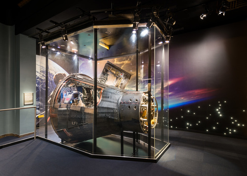
Cooling System
Spacecraft Cooling System Diagram
PRIMARY And SECONDARY Pump Switches
PRIMARY And SECONDARY Pump Lights
Cooling System Flow Schematic, Pre-Launch and Launch
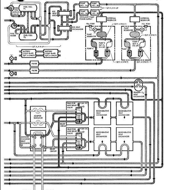
Cooling System Flow Schematic - Orbit
Coolant Tube Type Heat Exchanger Diagram
Coolant Temperature Control Valve Diagram
Launch Cooling Heat Exchanger Diagram
Spacecraft Cooling System Diagram
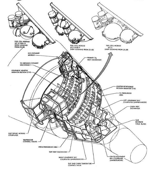
The spacecraft cooling system consists basically of two identical temperature control circuits functioning independently of each other to provide the cooling requirements for the spacecraft. Each cooling circuit consists of a pump package, thermostatic and directional control valves, various type heat exchangers, radiators, filters, and the necessary plumbing required to provide a closed circuit. The cooling system may be operated in either the primary and/or secondary circuit, and is capable of carrying maximum heat loads in either circuit.
The equipment coldplates, cabin and suit heat
exchangers are located in the reentry module. The upper radiator panels
are located in the retrograde section. The pump package, battery
coldplates, filters, electronic equipment coldplates, ground launch
cooling and regenerative heat exchangers and the lower radiator panels
are located in the adapter equipment section. System manual controls are
located on the pilots' pedestal console and the control switches,
warning lights and indicators are located on the center panel.
The cooling systems in spacecraft 8 through 12 are provided with a means of bypassing the coolant around the fuel cells rather than throug3 them. This provision is for ground operation when fuel cells are not in use.
During orbital flight, Monsanto MCS-198 coolant is supplied throughout the cooling system and thermostatic control valves regulate the coolant temperature.
Temperature sensors, located in the system, provided the necessary telemetering of system temperatures to ground stations.
Cooling system displays and controls are located on panels in the cabin as shown in section 3 and function as specified below
Dual concentric knobs are mounted between the ejection seats for suit and cabin temperature control. These knobs control the operation of valves regulating the flow rate of primary and secondary coolant through the suit and cabin heat exchangers for spacecraft 5 and 6. Spacecraft 8 does not have the cabin heat exchanger. Clockwise rotation results in increased temperatures.
A dual indicator provides for monitoring temperatures in the suit and cabin circuits. Range markings are calibrated in degrees Fahrenheit.
PRIMARY And SECONDARY Pump Switches
These switches are connected to the coolant pumps
power supplies, one switch for each power supply. Each switch has two
positions; ON and OFF. The switches are located on the center panel. On
spacecraft 8 through 12 B pump switch in each
loop changes the flow rate from 183 ib/hr to 140 lb/hr.
PRIMARY And SECONDARY Pump Lights
Pump lights illuminate when the pumps are activated. They are located above their respective switches near the top of the center panel. The RES LO lights illuminate when the coolant level in the reservoir is low.
This light illuminates when pressure in the evaporator builds up to 4.0 to -4.3 and is extinguished when the pressure falls to 2.9 to 3.4 psig.
This switch is connected to the evaporator heater and is used to heat the water in the evaporator before pumping.
The cooling circuit in which the cooling system operates is dependent upon the temperature loads generated by the equipment, spacecraft phase of flight and the temperature within the spacecraft cabin. Cooling is provided throughout the mission up to pre-retrograde firing. At this time the coolant pump packages are Jettisoned with the adapter equipment section, terminating spacecraft cooling.
Spacecraft 5 and 8 through 12 require both loops
to be operated contlnuously. In spacecraft 6 the primary circuit
operates continuously providing the required cooling during low
temperature loads. The secondary circuit is used, in conjunction with
the primly circuit, during phases of high temperature loads; namely -
launch, rendezvous, and pre-retrograde. Under normal heat loads, the
number 1 pump in the primary circuit provides the required cooling.
Under peak heat loads, the number 1 pump in the secondary circuit is
used with the primary circuit number 1 pump to provide maximum cooling.
In the event of a number 1 pump malfunction in either circuit, the
number 2 pump in that circuit is used. In the event of both pumps
failing in one circuit, both pumps of the remaining
circuit can be used to provide the required cooling. (Spacecraft 6 does
not have the number 2 pump in either circuit.)
During pre-launch an external supply of Monsanto MCS-198 coolant is circulated through the spacecraft ground cooling heat exchanger providing temperature control of the cooling system coolant. The number i pumps of the primary and secondary cooling circuits are activated, using an external power source, to provide the required cooling for spacecraft equipment and cabin. The spacecraft radiator switch, located on the center panel, is placed in the BYPASS position so the cooling system coolant by-passes the radiators and is directed through the ground cooling heat exchanger.
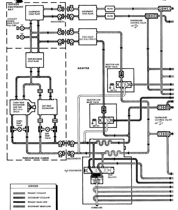
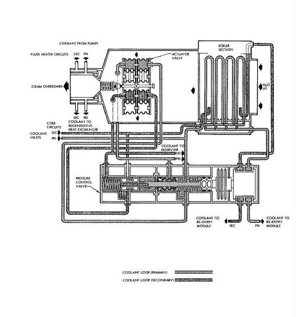
Cooling System Flow Schematic, Pre-Launch and Launch
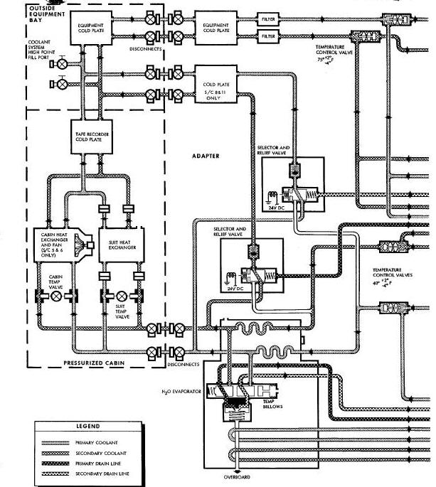
Coolant is circulated through each coolant loop by a positive-displacement gear pump. Spacecraft 5, and 8 through 12 are provided with 2 pumps in each loop. Spacecraft 6 has only one pump in each loop. Selection of loops and number of pumps is controlled manually.
The coolant is filtered, as it leaves the pump, and simultaneously flows to the inlet of the battery coldplate or fuel cell temperature control valve and primary oxygen heat exchanger.
The temperature control valve maintains the cooling temperature at the fuel cell or battery coldplate inlet at 75° +20 °to -40 ° F. Temperature increasing above setting will reduce by-pass flow. Coolant temperature from by-pass line varies from 80°F to 165°F. Coolant temperature from equipment lines varies from 60°F to 125°F.
Coolant enters the primary oxygen heat exchanger
and then is routed around the steam discharge lines in the water boiler
before it passes through the regenerative heat exchanger. It then passes
through the selector and pressure relief valve. This selector valve is
electrically actuated and when in the radiator by-pass position allows
the coolant to pass through the ground cooling heat exchanger
where the external supply of coolant flowing through the ground cooling
heat exchanger absorbs the heat from the spacecraft's coolant system.
The ground coolant heat exchanger has an airborne flow capacity of 336 lb/hr, per coolant loop, at 125°F. It has a ground coolant flow capacity of 425 lb/hr at 40°F.
The coolant is now ready to pass through the temperature control valve. This valve maintains the outlet temperature at 400° +20 °/-40 ° F. If the coolant entering the valve from the ground heat exchanger is below this range, a portion of the coolant is directed through the regenerative heat exchanger and then mixed at the valve. The coolant then flows through the water evaporator to the cabin and suit manual temperature control valves. These valves meter the coolant flow through the cabin and suit heat exchangers. The evaporator selector valve relief portion allows part of the coolant to by-pass the cabin and suit heat exchangers depending on the setting of the manual control valves. The selector portion of this valve allows the by-pass fluid to come from either downstream or upstream of the evaporator. The coolant continues through the various coldplates until it reaches the battery coldplates for spacecraft 6 or through the fuel cells on spacecraft 5, and 8 through 12. The coolant has now returned to the reservoir where the cycle is ready to be repeated.
Shortly before launch, the external cooling and electrical power are disconnected.
During launch the launch cooling heat exchanger
goes into operation in the following sequences. The heat transfer
characteristics and capabilities of the ground cooling heat exchanger no
longer exist. The Monsanto MCS 198 coolant fluid now with no place to
dissipate its internal heat, which is constantly being generated by and
absorbed from the loop components, circulates about the temperature
control valve of the heat exchanger. When the coolant temperature
exceeds 46° +40°/-20° F the temperature control valve opens to
pressurize a donut shaped bellows which unseats the poppet valve
exposing the water in the heat exchanger core to reduced pressure as
altitude increases during launch.
When spacecraft altitude exceeds 100,000 feet, water in the heat exchanger will boil absorbing heat from the coolant. This absorbed heat is then expelled overboard in the form of steam.
When the coolant reaches a temperature of 46°F, the temperature control valve repositions to relieve pressure to the donut shaped bellows holding the poppet open. As this pressure diminishes, a spring behind the poppet will reposition it to the closed position. The evaporator selector valve is positioned to allow all flow to go through the evaporator.
The water boiler water reservoir is constantly replenished from the suit heat exchanger water separator, and if the need arises, from the drinking water supply tank.
After orbiting for approximately 30 minutes, to allow the radiator to cool after being subject to launch heating, the coolant flow is directed through the space radiators by manual selection of the radiator switch located on the center panel. This by-passes the ground cooling heat exchanger. The evaporator selector valve is also positioned so that only the flow to the suit and cabin heat exchangers pass through the evaporator.
Prior to retrograde firing, the coolant pump
packages, radiators, batteries and various heat exchangers are
jettisoned with the adapter equipment section. Prior to adapter
jettisoning and retrograde firing the number 1 coolant pumps for both
the primary and secondary coolant circuits are activated. The suit,
cabin, and equipment bays are cooled to as low a temperature as
possible, before the adapter
equipment section is Jettisoned.
Cooling System Flow Schematic - Orbit
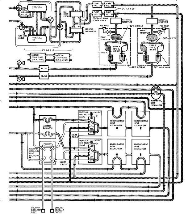
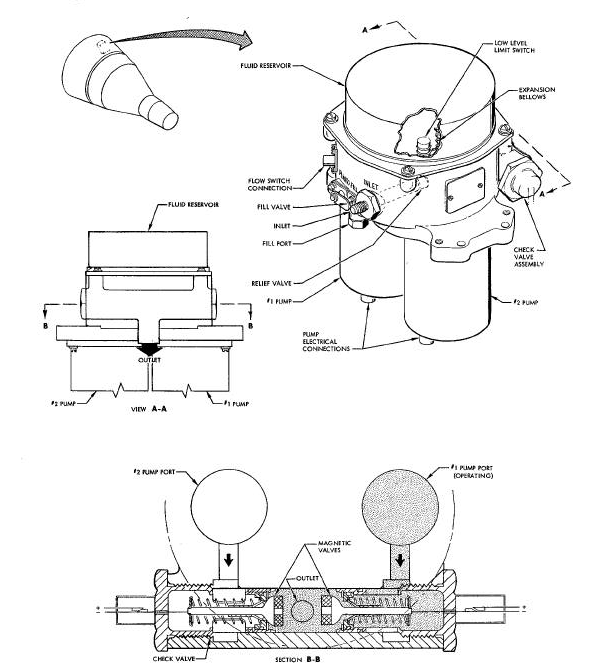
The pump package for each coolant circuit incorporates two constant displacement electrical pumps, two pump inverters, an external reservoir, filters, relief and check valves. The pump package is located in the adapter equipment section. Pump selection is provided by switches on the pilots' center panel. A pump failure warning light is provided on the center panel. When a pump is activated the coolant flows from the reservoir to the pump, which circulates the coolant through the cooling circuit. The coolant returns to an external reservoir that compensates for thermal expansion, contraction, and leakage of the coolant. A 100 micron filter downstream of the pump prevents contamination of the cooling system. Check valves in the pump package prevent the operating pump from pumping coolant into the redundant pump. Flow sensing switches illuminate a pump failure lamp on the pilots' center panel in the event of pump failure.
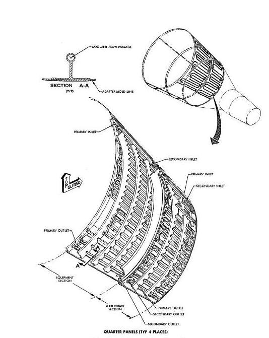
The spacecraft radiator consists of two circumferential radiator panels
made of 0.25 inch diameter cooling tubes. There are four sections of
tubing to each radiator panel. The tubing is manufactured as part of the
spacecraft structure. Each panel incorporates two parallel cooling
circuits, one for the primary cooling circuit and the other for the
secondary circuit. During orbit the cooling
system coolant is circulated through the radiator. The heat of the
coolant radiates into space, lowering the temperature of the coolant.
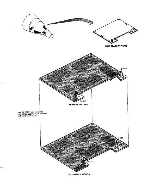
The coldplates, other than the battery coldplates, are plate fin
constructed units incorporating parallel coolant system passages.
Coldplates are fabricated from aluminum. Battery, electrical, electronic
and other heat generating components are mounted on coldplates. The
coolant flowing through the coldplates absorbs the heat generated by the
components preventing overheating of the
operating equipment.
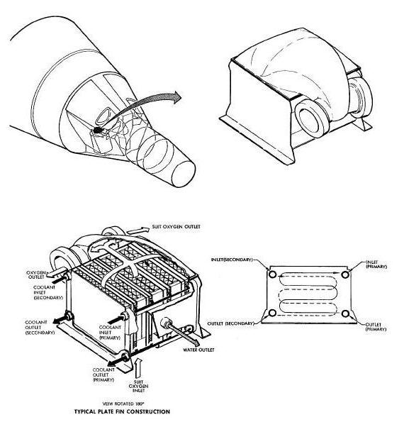
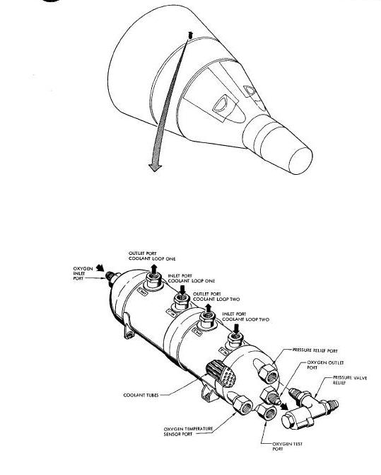
Two types of heat exchangers are used in the spacecraft; namely, plate
fin constructed and shell and tube constructed heat exchangers. The
suit, cabin, water evaporator, ground cooling and regenerative heat
exchangers are of plate fin construction. The primary oxygen heat
exchanger is of shell and tube construction. The coolant absorbs heat
from the cabin, suit and regenerative
heat exchangers. The ground cooling and water evaporator heat exchangers
permit heat transfer to cool the coolant. The primary oxygen heat
exchanger is designed so heat transfer will heat the primary oxygen to a
desired temperature.
Coolant Tube Type Heat Exchanger Diagram
Temperature control valves are provided in both the primary and secondary cooling circuits. These valves are located at the radiator outlets and at the inlets to the battery coldplates or fuel cells.
Coolant Temperature Control Valve Diagram
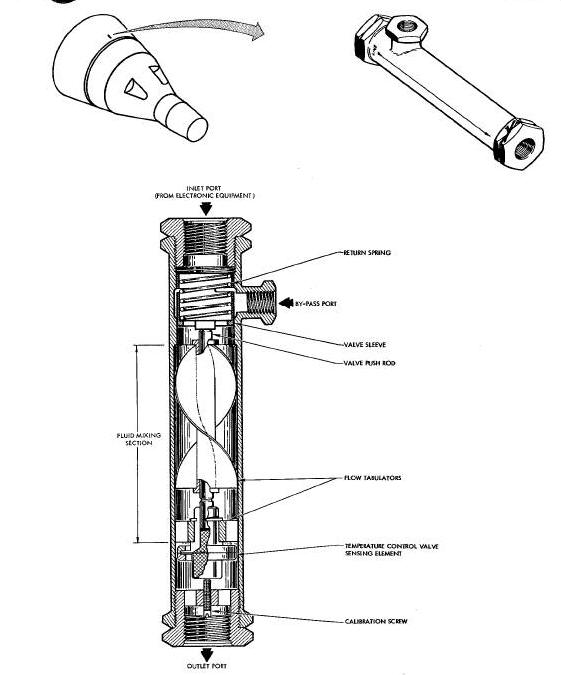
The temperature control valve located in the coolant system radiator outlet automatically maintains the coolant outlet temperature at 40° +2°/-4° F as long as the radiator capacity has not been exceeded.
The temperature control valve located in the battery coldplate inlet automatically maintains the coolant inlet temperature at 75 +3°/-4° F or above.
The temperature control valve contains a piston that regulates the inlet
flow to the valve. The piston is spring loaded on one side. A
thermostatic actuator on the opposite side of the piston determines
piston movement, which in turn regulates the coolant flow through the
valve. The thermostatic actuator, which is located to accurately sense
mixing temperature, consists of an encapsulated
wax pellet that expands or contracts as temperature varies. As
temperature around the pellet increases, the wax expands exerting
pressure on the diaphragm. The diaphragm moves a piston, which in turn
controls the inlet flow to the valve. Temperature reduction around the
wax decreases the pressure in the pellet cup allowing the spring to
reposition the piston regulating the flow of coolant
through the valve.
The launch cooling heat exchanger is located in the adapter section. Via its relief valve it can dump liquids overboard, or if the temperature control valve senses temperature greater than 50°F, it can control the outlet temperature of the primary and secondary coolants to 46° +4°/-2° F. In addition, it serves as a water reservoir, storing water until it is needed for cooling.
Launch Cooling Heat Exchanger Diagram
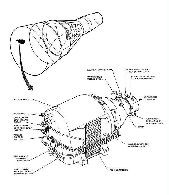
This evaporator consists of a wicking type heat exchanger and is capable
of storing seven pounds of water. A temperature control valve has been
set to control the outlet coolant temperature 46 +4°/-2° F. A relief
valve opens and allows excess water to be dumped overboard at 2.75 +/-
0.25 psi differential and reseats at 2.0 psi differential minimum. An
electrical heater is provided in
the poppet to prevent ice formation. Coolant flow capacity is 366 lb/hr
at 40°F.
Water flow capacity is 3 lb/min when cooling is not required from the evaporator. Maximum operating pressure in the fluid heater coolant circuits is 230 psig, and lO0 psig in the core circuits. Maximum operating pressure in the water circuit is 20 psig with exit port relief valve in normal operation.
The steam exit duct is continuously heated by coolant coming from the primary oxygen heat exchanger to prevent ice formation.
A loss of pressure in either coolant loop will not affect the operation of the valve.