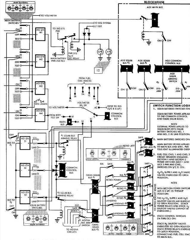
Schematic-Electrical Power System
Schematic-Electrical Power System 3
Schematic-Electrical Power System
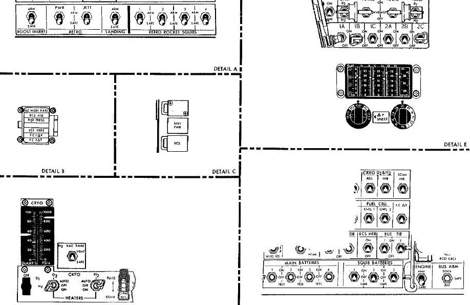
POWER DISTRIBUTION RELAY PANEL
ADAPTER POWER SUPPLY RELAY PANEL
RSS/Fuel Cell System Functional Diagram
Dual Pressure Regulator and Relief Valves
SYSTEM DESCRIPTION
The Electrical Power System for the Gemini Spacecraft basically consists of two fuel cell battery sections, four silver-zlnc main batteries and three silver zinc squib batteries (spacecraft 6 uses three 400 ampere/hour sliver-zinc batteries in lieu of the fuel cell batteries). No primary ac electrical power system Is provided for the spacecraft. Devices requiring ac power obtain this power from self-contained inverters within the individual systems.
The Electrical Power System includes switches, circuit breakers, relay panels, ammeters, a voltmeter and telelights which provide control, distribution and monitoring for the system. Also included as an Electrical Power System subsystem Is the Reactant Supply System (RSS) which provides storage and control of the reactants (hydrogen and Oxygen) used for fuel cell battery operation (not applicable to spacecraft 6). Provisions are made for utilizing external power and remote monitoring of the spacecraft power buses during ground tests and pre-launch operations.
Schematic-Electrical Power System
'[
Schematic-Electrical Power System
Schematic-Electrical Power System 3
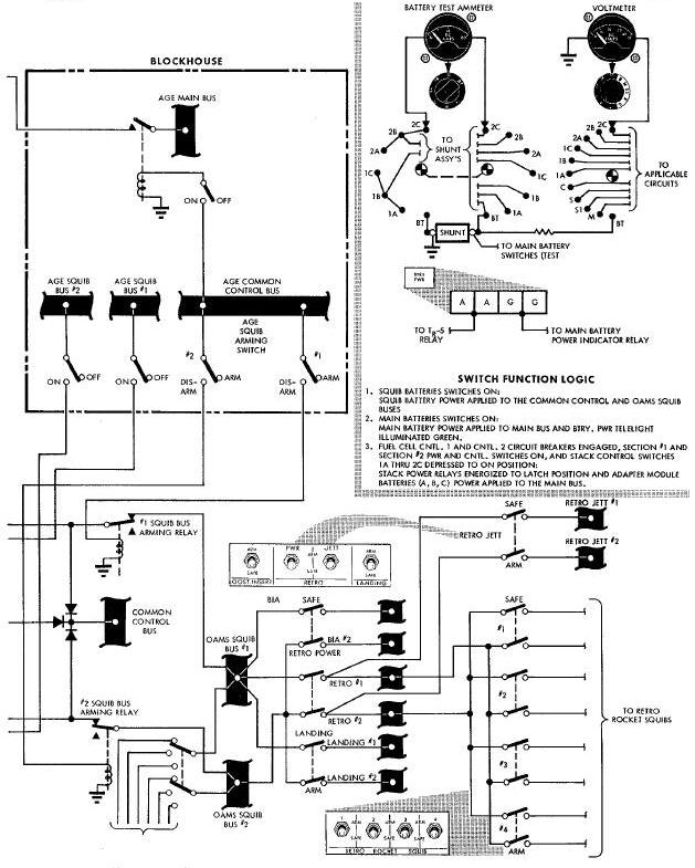
The two fuel cell battery sections and four
main batteries provide dc power to the spacecraft main power bus (on
spacecraft 6, the three adapter module batteries and the four main
batteries provide dc power to the main bus). The squib buses via the
individual squib bus arming switches.
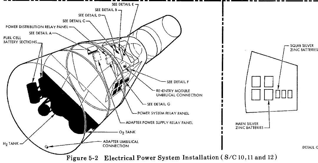
The fuel cell battery sections, along with the required RSS components,
are installed in the RSS/fuel cell module (Figure 5-6, 5-7 and 5-8)
which is located in the spacecraft equipment adapter section (on
spacecraft 6, three silver-zinc batteries are installed in the adapter
battery module (Figure 5-9) which is located in the spacecraft equipment
adapter section.) The main and squib batteries are installed in the
right cabin equipment bay.
A power system monitor consisting of a delta pressure indicator, three dual-vertical-readout ammeters and an ac/dc voltmeter, with associated selector switches, is located on the right instrument panel.
The BTRY PWR sequence light, FCAP telelights, 02 and H2 heater switches, 02/H2 quantity indicator (integral with Environmental Control system (ECS) 02 indicator) and selector switch are located on the center instrument panel. The 02 and H2 heater switches, quantity indicator and selector switch are identified as CRYO switches and indicator.
An 02 CROSS-FEED switch is also located on the center instrument panel. This switch is identified as H2 TANK VAC. The power system relay panel, power distribution relay panel and adapter power supply relay panel are located in the left equipment area of the cabin.
SYSTEM OPRARATION
PRE-LAUNCH
In order to conserve spacecraft battery power, external electrical power is utilized during the pre-launch phase of the mission. External power is supplied to the spacecraft common control, main and squib power buses through umbilical cables connected to the re-entry module and equipment adapter section umbilical receptacles. The external power source is provided by Aerospace Ground Equipment (AGE).
SQUIB Switches 1 and 2 must be placed in the umbilical (UMB) position in order to apply external power to the spacecraft squib buses. Remote control of the spacecraft squib bus arming relays, and remote monitoring of the spacecraft power buses is also accomplished through the re-entry and adapter umbilical cables.
Prior to launch, al1 MAIN BATTERIES and SQUIB BATTERIES switches, SECTION POWER switches and stack control switches (IA through 2C) are set to the ON position to insure maximum redundancy of the Electrical Power System during the launch phase of the mission. The fuel cell batteries are activated in sufficient time prior to launch, to insure launch readiness of the fuel cell batteries and RSS.
The common control bus and OAMS squib buses are switched from external power to the squib batteries in sufficient time prior to launch, to verify the squib battery circuits. The BIA buses are armed prior to launch by setting the BOOST-INSERT ARM/SAFE switch to ARM position.
The re-entry and equipment adapter section umbilicals are disconnected from the spacecraft Just prior to lift-off. Normally, umbilical separation is accomplished by an electrical solenoid device. A backup method of separation is also provided by a lanyard initiated mechanism which is actuated by movement of the launch vehicle.
ORBIT
From launch time until booster separation and insertion into orbit, both the fuel cell battery sections and the four main batteries are connected in parallel to the main power bus. After booster separation is accomplished, the MAIN BATTERIES switches are placed in the OFF position to conserve the main battery power. Also the pilots will disarm the BIA squib buses by setting the BOOST-INSERT ARM/SAFE switch to SAFE.
In the event of an abort, all squib buses required for the abort function, which are not armed prior to launch, are armed via the abort relays controlled by the Sequential System. These relays effectively bypass the applicable squib bus arming switches which normally arm these buses.
The SQUIB BATTERIES switches remain in the ON position throughout the entire mission until landing is accomplished. All three squib batteries are connected to the common control bus through diodes for individual fault protection. Squib batteries 1 and 2 are connected to the two 0AMS squib buses via the de-energized squib bus arming relays.
The 02 CROSS-FEED switch reins in the CLOSED position except in the event of a loss of RSS 02 tank pressure. This switch controls the 02 crossfeed valve, which provides the capability of connecting the ECS 02 supply to the fuel cell battery sections. (Refer Figure Below).
Schematic-Electrical Power System
The H 2 TANK VAC switch provides the capability of venting the area between the inner and outer wall of the RSS H 2 supply tank to outside vacuum in space. This switch, when in VENT position, initiates a pyrotechnic cutter device to perform this function. The H2 TANK VAC switch remains in the SAFE position until the pilots elect to perform this function.
The BUS TIE switches remain in the OFF position unless the necessity arises where the pilots must use main bus power to fire the squibs. The BUS TIE switches provide a method of connecting the main bus to the OAMS squib and common control buses. The Agena BUS ARM switch will be used according to the mission requirements.
A small percentage of the reactant gases must be purged from the fuel cell batteries periodically to insure that the impurities contained in the feed gases do not restrict reactant flow to the cells and to remove any accumulation of product water in the gas lines. This purging functions performed by the pilots manually actuating the 02 and H2 PURGE switches. The pilots may increase the flow of gases to the fuel cell sections for more effective purging by setting the X-0VER switch to ON position.
At 256 seconds before retrograde time (TR-256) the pilots will arm the retrograde squib buses by setting the RETRO PWR ARM/SAFE switch and the individual RETRO ROCKET SQUIBS No. l, 2, B or 4 ARM/SAFE switches to ARM position. The retrograde rockets are used according to the mission requirements.
The MAIN BATTERIES switches must be returned to the ON position at TR-256 seconds to insure continuity of main bus power at the time of separation of the equipment adapter section# containing the RSS/fuel cell module , from the spacecraft. There is no automatic switching provided for this function.
The stack control switches (1A through 2C) and the SECTION 1 and SECTION 2 POWER switches are set to OFF position after the main batteries are properly connected to the main bus.
After retrograde rocket firing has been accomplished, the pilots will set the RETRO JETT ARM/SAFE switch to ARM. This switch provides a method of arming the JETT RETRO switch (center instrument panel), and is effectively an interlock to prevent inadvertent Jettisoning of the retrograde section prior to firing of the retrograde rockets.
After the equipment adapter and retrograde sections are separated from the spacecraft, the pilots will disarm the retrograde squib buses by setting the RETRO PWR ARM/SAFE switch, RETRO JETT ARM/SAFE switch and RETRO ROCKET SQUIBS ARM/SAFE switches to SAFE position. At this time, the landing squib buses are armed by setting the LANDING ARM/SAFE switch to ARM position.
After landing is accomplished, the pilots will disarm the landing squib buses by returning the LANDING ARM/SAFE switch to SAFE. At this time, power will be removed from the OAM3 squib buses by setting SQUIB BATTERIES switches 1 and 2 to OFF position. All unnecessary electrical equipment will be deactivated to conserve the remaining spacecraft batteries for recovery equipment operation. SQUIB BATTERIES switch 1 and the MAIN BATTERIES switches will remain in the ON position to power the main and control buses throughout the recovery phase of the mission.
Throughout the mission, visual displays of bus voltage and current are provided by the system voltmeter and ammeters.
The ammeters monitor individual fuel cell stack current (IA through 2C). The voltmeter, used in conjunction with a selector switch, displays individual fuel cell stack voltage, common control bus voltage, OAMS squib bus 1 and 2 voltage, Inertial Guidance System (IGS) inverter output voltage , main bus voltage and individual main battery voltage with the selector switch in Battery Test (BT) position and a particular MAIN BATTERIES switch in TEST position.
The delta pressure indicator, in conjunction with a selector switch, provides a visual display of 02 versus H 2 and 02 versus H20 differential pressure in the fuel Cell battery sections. In the event that the differential pressure exceeds the prescribed limits, the pilots must evaluate the fuel cell battery performance, and if a malfunction exists, shut down the malfunctioning fuel cell battery section by setting the applicable fuel cell power and stack control switches to OFF position.
An out of tolerance delta pressure indication is also provided by the fuel cell delta pressure (FCAP) telelights on the center instrument panel. The lights are illuminated red when a malfunction exists.
The reactant (02 and H2) supply quantities are displayed on the ECS 02 quantity indicator(center instrument panel) when the associated selector switch is set to FC 02 or FC H2 positions. This indicator and switch are identified as CRY0 02 and H2.
The BTRY PWR sequence light, located on the center instrument panel, is illuminated amber at TR-256 seconds during the mission by action of the TR- 5 relay in the power system relay panel. This informs the pilots that they must return the MAIN BATTERIES switches to ON position to insure continuity of main bus power due to the impending separation of the equipment adapter section containing the adapter power supply (fuel cell battery sections on spacecraft 5 and 8 through 12 and silver-zinc batteries on spacecraft 6). With all main batteries properly connected to the main bus, the BTRY PWR sequence light is illuminated green.
Displays of common control bus voltage, main bus voltage, OAMS squib bus voltage, and adapter module battery voltage is provided by the system voltmeter and selector switch. Individual main battery voltage (with the particular battery removed from the main bus) is monitored with the voltmeter selector switch in BT position and the applicable MAIN BATTERIES switch in TEST position.
The four main batteries are 45 ampere/hour, 16
cell, silver-zinc batteries. The three squib batteries are 15
ampere/hour, 16 cell, silver-zinc batteries. The squib batteries are
special high-discharge-rate batteries which will maintain a terminal
voltage of 18 volts for one second under a 75 ampere load.
The main and squib battery cases are made of titanium. The approximate activated (wet) weight for each squib battery is 8 lbs and each main battery 17 lbs. The adapter module battery cases (spacecraft 6) are constructed of magnesium and the approximate wet weight of each battery is 118 lbs.
The battery electrolyte consists of a 40 percent solution of reagent grade potassium hydroxide and distilled water. The main and squib batteries have a vent valve in each cell designed to prevent electrolyte loss and will vent the cell to atmospheric pressure in the event a pressure in excess of 40 psig builds up within the cell.
All of the silver-zinc batteries are equipped with relief valves which maintain a tolerable interior to exterior differential pressure in the battery cases. The batteries are capable of operating in any attitude in a weightless state. Prior to installation into the spacecraft, the batteries are activated and sealed at sea level pressure. All of the batteries are coldplate mounted to control battery temperature.
The power system relay panel contains relays necessary for controlling and sequencing power system functions. The panel contains the control relays for the fuel cell battery system and RSS, main battery power sequence light relay, TR- 5 relay and the squib bus arming relays.
POWER DISTRIBUTION RELAY PANEL
The power distribution relay panel contains the relays required for arming the retrograde squib buses in the event of an abort. These relays are controlled by the Sequential System.
ADAPTER POWER SUPPLY RELAY PANEL
The adapter power supply relay panel contains relays necessary for controlling adapter module power to the main power bus. The relay panel contains the stack power relays which connect the individual fuel cell stacks tothe main bus. The panel also contains diodes used for reverse current protection between the adapter power supply and the spacecraft main power bus.
Individual main battery voltage may be monitored with the voltmeter selector switch set to BT position and a particular MAIN BATTERIES switch set to TEST position. The voltmeter displays applicable adapter module batteries (A, B and C) voltage when the selector switch is set to 1A, IB, 1C or 2A, 2B, 2C positions. The voltmeter has a 0-50 vdc range.
The power system monitor consists of five vertical reading indicators; a delta pressure indicator, three dual-readout ammeters and an ac/dc voltmeter. The delta pressure indicator and voltmeter are used in conjunction with selector switches located just below on the instrument panel.
The ammeters provide a display of individual fuel cell stack (1A through 2C) current. The voltmeter, with the selector switch in appropriate position, displays individual fuel cell stack voltage, main bus, squib bus and common control bus voltage, individual main battery voltage (with a particular MAIN BATTERIES switch in TEST position) and IGS inverter output voltage with the selector switch in AC position. The AC position on the selector switch Is inoperative on spacecraft 5. The voltmeter has a 20-33 ac volt range and an 18-33 dc volt range.
The delta pressure indicator has a 0-1.5 psi range with the selector switch in either H2 position and a 0-6 psi range with the selector switch in either H20 position. This indicator displays 02 versus H2 differential pressure and 02 versus H20 differential pressure for each fuel cell battery section.
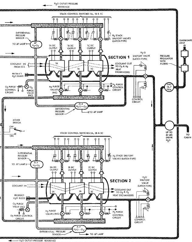
The fuel cell batteries used in the Gemini Spacecraft are of the solid ionexchange membrane type using hydrogen (H2) for fuel and oxygen (02) for an oxidizer. The fuel cell battery system is comprised of two separate sections which are sealed in air tight pressure containers. Each section is made up of three interconnected fuel cell stacks with plumbing for transferring hydrogen, oxygen and product water. (See Figure Below).
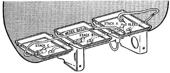
Fuel Cell Battery Section
Each fuel cell stack consists of 32 individual fuel cells. Each basic fuel cell is made up of two catalytic electrodes separated by a solid type electrolyte in laminated form.
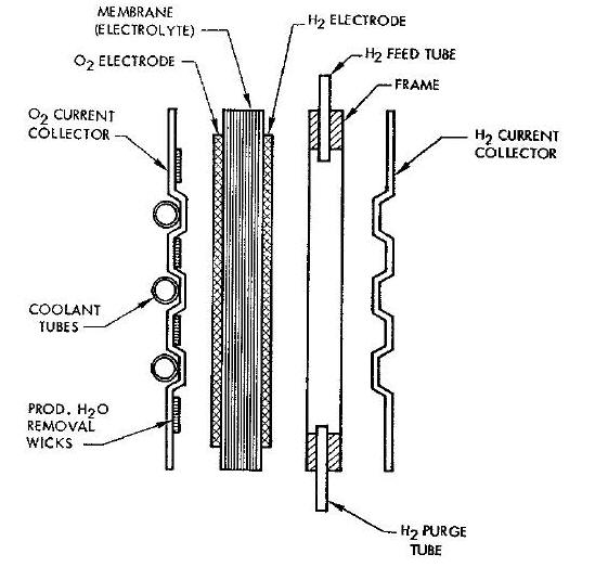
The electrolyte is composed of a sulfonated styrene polymer (plastic) approximately 0.1 inches thick. Thin films of platinum catalyst, applied to both sides of the electrolyte, act as electrodes and support ionization of hydrogen on the anode side of the cell and oxidation on the cathode side of the cell.
A thin titanium screen, imbedded into the platinum catalytic electrode, reduces the internal resistance along the current flow path from the electrode to the current collector and adds strength to the solid electrolyte.
On the hydrogen side of the fuel cell, a current collector is attached by means of a glass-cloth-reinforced epoxy frame which assures a tight seal around the edges of the cell, forming a closed chamber. Ribs in the collector are in contact with the catalytic electrode on the fuel cell, providing a path for current flow.
The hydrogen fuel is admitted through an inlet tube in the frame of the current collector and enters each gas channel between the collector ribs by way of a series of slots in the tube. Another tube provides a purge outlet, making it possible to flush accumulated inert gases from the cell. The collector plate is made of approximately 0.003 inch thick titanium.
On the oxygen side of the cell, a current collector of the same configuration and material as the hydrogen side collector is attached. Its ribs, located at right angles to those of the other collector, provide structural support to the electrolyte-electrode structure.
A Dacron cloth wick, attached between the ribs, carries away the product water through capillary action, by way of a termination bar on one side of the assembly. Oxygen is admitted freely to this side of the fuel cell from the oxygen filled area of the section container. The cell cooling system consists of two separate tubes bonded in the cavity formed by the construction of the oxygen side current collector and the back side of the hydrogen current collector. Each tube passes through six of the collector ribs and has the cooling capacity to maintain operating temperature. The cooling of the oxygen current collector, which holds the product water transport wicks provides the coldplate for water condensation from the warmer oxygen electrode.
The individual fUel cell assemblies are arranged in series to form a stack as shown in the Fuel Cell Stack Assembly.
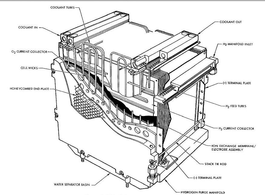
When
assembling the cells into a stack, the ribs of the oxygen side current
collector contact the solid electrolyte of the fuel cell assembly.
Titanium terminal plates are installed on the ends of the two outside
cells to which connections are made for the external circuit. End
plates, which are honey-comb structures of epoxy-glass laminate 0.5 inch
thick, are installed
on the outside of the terminal plates.
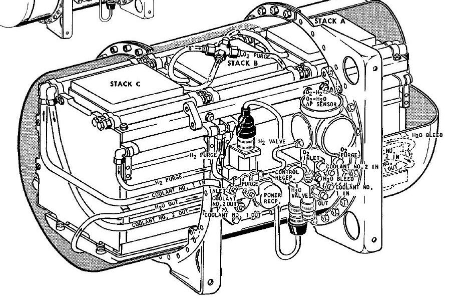
Stainless steel insulated tie rods hold the stack together and maintain a compression load across the area of each cell assembly. This assures proper contact of the solid electrolyte with the ribs of each current collector. The fuel cell stacks are packaged in a pressure tight container, together with the necessary reactant and coolant ducts and manifolds, water separator for each stack, and required electrical power and instrumentation wiring.
The hydrogen inlet line, hydrogen purge llne, and the two coolant lines for each cell lead from their respective common manifolds running the length of the stack. The manifolds are made of an insulating plastic material and the individual cell connections are potted in place after assembly to provide a leak-tight seal. The oxygen sides of the cells are open to the oxygen environment surrounding the fuel cell assemblies within the container.
An accessory pad is mounted on the outside of the fuel cell section container. It includes the gas inlet and outlet fittings, purge and shutoff valves, water valve and electrical connectors. Structurally, the container is a titanium pressure vessel consisting of a central cylinder with two end covers and two mounting brackets. Within the container, the fuel cell stacks are mounted on fiberglass-impregnated epoxy rails by bolts which pass through the stack plates. These rails are in turn bolted to the mounting rings sandwiched between the two flanges on the section container.
The hydrogen manlfolds on each stack within a section are parallel fed with a hydrogen shutoff valve and check valve in the feed line to each stack. Oxygen is fed into the section container so that the entire free volume of the container contains oxygen at approxlmately 22.5 psia. The coolant reaches the fuel cell battery sections by two separate isolated lines. Any malfunction in the coolant line in one section will not affect the cooling function of the coolant line in the other section.
Each stack in the section has its own water-oxygen separators which are manifolded into a single line coming out of the section container. All hydrogen, oxygen coolant, electrical and water storage pressure line connections at the section container are fastened to standard bulkhead fittings on the accessory pad.
After the stacks are completely assembled within the container, all void spaces are filled with unicellular foam. The purpose of this foaming is for vibration dampening, accoustical noise deadening and minimizing free gas volume to prevent possible fire propagation. Thin plastic covers are placed over the top and bottom of each stack to manifold oxygen to the stack and to keep the foam material from entering areas around the coo1_nt manifolds and oxygen water separator.
The basic principle by which the fuel cell operates to produce electrical energy and water, is the controlled oxidation of hydrogen. This is accomplished through the use of the solid electrolyte ion-exchange membrane. On the hydrogen side of the fuel cell, hydrogen gas disassociates on the catalytic electrode to provide hydrogen ions and electrons. The electrons are provided a conducting path of low resistance by the current collector, either to an external load or to the next series-connected fuel cell.
When a flow of electrons is allowed to do work and move to the oxygen side of the fuel cell, the reaction will proceed. By use and replacement, hydrogen ions flow through the solid electrolyte to the catalytic electrode on the oxygen side of the fuel cell. When electrons are available on this surface, oxygen disassociates and combines with the available hydrogen ions to form water.
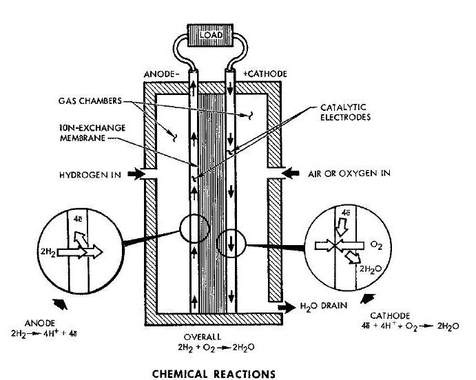
The oxygen current collector provides the means of distributing electrons and condensing the product water on a surface to be transported away by the wick system through capillary action. The individual cell wicks are integrated into one large wick which routes the water to an absorbent material that separates the water from the gas.
By using the oxygen outlet pressure as a reference, a small pressure differential is obtained over the length of the water removal system. This pressure is sufficient to push the gas-free water toward the storage reservoir.
Waste heat, generated during the fuel cell battery operation, is dissipated by means of the recirculating coolant provided by the spacecraft cooling system. In addition, the total coolant flow provides the function of preheating the incoming reactant gases. In the spacecraft, the reactant gases are suFplied to the fuel cell battery sections by the RSS. This system contains the reactant supply tanks, control valves, heat exchangers2 temperature sensors and heaters required for management of the fuel cell reactants. (Principal of Operation).
The RSS is essentially a subsystem for the fuel cell battery sections. The system provides storage for the cryogenic hydrogen and oxygen, converts the reactants to gaseous form and controls the flow of the gases to the fuel cell battery sections. The RSS components are installed in the RSS/fuel cell module. The RSS 02 requirements are supplied from a central cryogenic 02 tank located in the RSS/fuel cell module. This vessel also supplies 02 to the ECS. See Figure 5-6, 5-7 and 5-8 for component installation and Figure 5-14 for a functional diagram.
Two tanks are utilized to separately contain the cryogenic hydrogen and oxygen required for the operation of the fuel cell battery sections. The tanks are thermally insulated to minimize heat conduction to the stored elements which would cause the homogeneous solution to revert to a mixture of gas and liquid. The tanks are capable of maintaining the stored liquids at supercritical pressures and cryogenic temperatures.
The approximate total amount of liquid stored in the hydrogen vessel is 22.25 lbs for long mission configurations and 5.80 ibs for short mission configurations. The approximate total amount of liquid stored in the oxygen vessel is 106 lbs (for ECS and RSS) and 46.0 Ibs
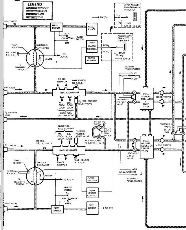
RSS/Fuel Cell System Functional Diagram
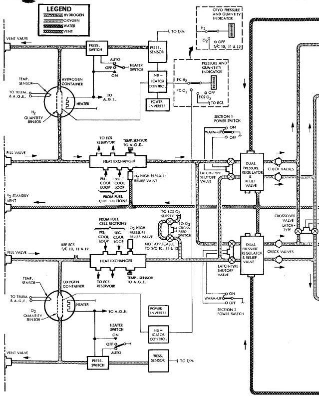
RSS/Fuel Cell System Functional Diagram

The hydrogen vessel is composed of titanium alloy and the oxygen vessel Is made of a high strength nickel base alloy. Both vessels are spherical in shape and double walled. A vacuum space between the inner and outer wall (approximately one inch) provides thermal insulation from ambient heat conduction. The inner wall is supported in relation to the outer wall by an insulating material supplemented by compression loading devices.
Each storage tank contains a fluid quantity sensor, a pressure sensor, a temperature sensor and an electrical heater installed in the inner vessel in intimate contact with the stored reactants. The fluid quantity sensor is an integral capacitance unit which operates in conjunction with an indicator control unit containing a null bridge amplifier.
The sensor varies the capacitance (in proportion to fluid level) in a circuit connected to the null bridge amplifier. The amplified signal is then used to drive a servo motor, which in turn operates a visual indicator for quantity indication. Power inverters supply 400 cycle, 26 vac power to the fluid quantity circuits.
The temperature sensor is a platinum resistance device capable of transmitting a source signal to a balanced bridge circuit. The sensor provides cryogenic fluid temperature monitoring for telemetry and AGE.
The pressure sensor is a dual resistive element, diaphragm type transducer. The sensor provides signals for cryogenic fluid pressure monitoring on a spacecraft meter. The electrical heaters provide a method of accelerating pressure build-up in the reactant supply tanks. The heaters may be operated either in a manual or automatic mode. In the automatic mode a pressure switch removes power from the heater element when the tank pressure builds up to a nominal 900 psig in the oxygen tank and a nominal 250 psig in the hydrogen tank. In the manual mode a spacecraft pressure meter indicates proper switch operation.
The fill and vent valves provide a dual function in permitting simultaneous fill and vent operations. Quick disconnect fittings are provided for rapid ground service connection to both the storage tank fill check valve and the vent check valve. When fill connections are made, the pressure of the ground service connection against the fill and vent valve poppet shaft simultaneously opens both the fill and vent ports. When ground service equipment is removed, the valve poppet automatically returns to its normally spring-loaded-closed position. The vent check valve is a single poppet type, spring-loaded-closed valve which opens when system pressure exceeds 20 psig to relieve through the fill and vent valve vent ports.
The supply temperature control heat exchangers are finned heat exchangers in which the supply fluid temperature is automatically controlled by absorbing heat from the recirculating coolant fluid of the spacecraft cooling system. The special doublepass design precludes freezing of the coolant and assures a reactant fluid supply at 50°F minimum and 140 ° maximum.
Dual Pressure Regulator and Relief Valves
The dual pressure regulator and relief valves are normally open poppet type regulators which control downstream pressure to the fuel cell battery sections. The regulators maintain the hydrogen pressure at approximately 21.7 psia and the oxygen pressure at approximately 2.2 psia. The oxygen side of the regulators is referenced to hydrogen pressure. The hydrogen side of the regulators is referenced to produce H20 pressure.
The relief valves provide over pressurization protection for the regulated pressure to the fuel cell battery sections. This valve is precalibrated to operate at a pressure of approximately 10 psia above the normal supply level.
The high pressure relief valves are single poppet type, spring-loaded-closed valves which provide system overpressurization protection. The valves vent system gas to ambient when pressure exceeds the system limits.
The solenoid shutoff valves are solenoid operated latching type valves which eliminate fluid loss during the nonoperating standby periods. The valves are normally open and are closed only during fill and standby periods by applying power to the solenoids.
The crossover valve is a solenoid operated latching type valve which provides the capability of selecting both dual pressure regulators to supply hydrogen and oxygen to a fuel cell battery section for the purpose of increasing flow rate for more effective purging. The crossover valve is controlled by the X-OVER switch on the right instrument panel.
During pre-launch, the two separate reactant supply tanks are serviced (using AGE equipment) with liquid hydrogen and oxygen. After the tanks are filled, in order to accelerate pressure buildup within the tanks, the internal tank heaters are operated, utilizing external electrical power. In approximately one hour the liquid is converted into a high density, homogeneous fluid at a constant pressure. During the fill operation, the solenoid shutoff valves between the storage tanks and the dual pressure regulators are closed. Once operating pressure is obtained,the solenoid shutoff valves may be opened by applying power to the coil of the valves. The high density, homogeneous fluid will then flow upon demand.
The fluid flows from the supply tanks to the heat exchangers. The fluid temperature, when entering the heat exchangers is approximately -279°F for the oxygen and approximately -423°F for the hydrogen. The heat exchangers absorb heat from the recirculating coolant fluid of the spacecraft cooling system. This heat applied to the high density fluid, raises the temperature of the reactants to approximately 50°F to 140°F.
The reactants, now in gaseous form, flow through the heat exchangers, past the high pressure relief valves and AGE temperature sensors, to the supply solenoid shutoff valves. During fuel cell battery operation, if the demand on the fluid flow is inadequate to keep tank pressures within limits, the high pressure relief valves will vent, externally, the excess fluid. The AGE temperature sensors on the heat exchangers are used for pre-launch checkout only.
The reactants flow through the supply solenoid shutoff valves to the dual pressure regulator and relief valves. The dual pressure regulators reduce the pressure of the reactants to approximately 21.7 psia for the hydrogen and approximately 20.5 psia for the oxygen. The gas now flows through the manual shutoff valves and is then directed to the fuel cell battery sections at a flow rate that is determined by both the electrical load applied and the frequency of purging. The flow rate of the gases may be increased for more effective purging by opening the crossover valve.
After launch, the supply tank heaters are
operated by spacecraft power. The
heaters operate as required to maintain proper system pressures.
A
AGE - Aerospace Ground Equipment
B
BT - Battery Test
E
ECS - Environmental Control system
F
FCAP - fuel cell delta pressure
I
IGS - Inertial Guidance System
R
RSS - Reactant Supply System
U
UMB - Umbilical