EXTRA-VEHICULAR ACTIVITY
EXTRA-VEHICULAR ACTIVITY Diagram
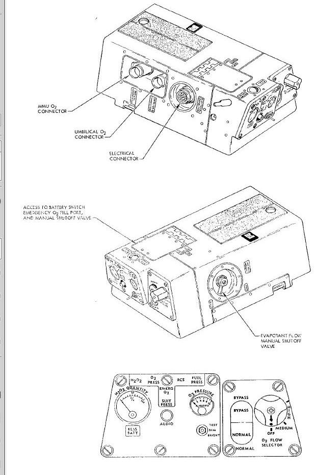
Typical Locations of EVA Equipment and Support Provisions
Oxygen Loop - Normal Operation
ELSS Chest Pack Functional Diagram
Oxygen Loop - Emergency Operation
Chest Pack Electrical Components
HAND HELD MANEUVERING UNIT OPERATION
Hand Held Maneuvering Unit Diagram
ELSS 25 FOOT UMBILICAL AND ELECTRICAL JUMPER
ELSS 25 Foot Umbilical and Electrical Jumper Diagram
ELSS 50 FOOT UMBILICAL Diagram
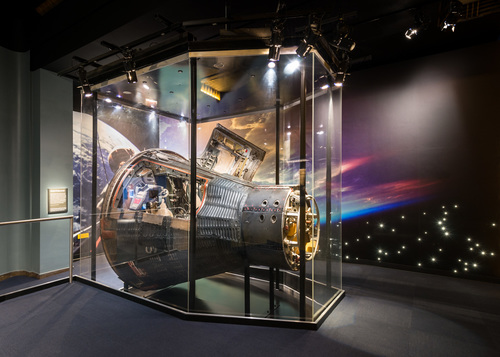
Extra-Vehicular Activity (EVA) is that portion of the mission during which the pilot egresses from the cabin to conduct experiments and perform maneuvers. The purpose of EVA is to: determine man's performance capabilities wearing a pressurized suit in a free space environment, demonstrate the ability to perform controlled maneuvers in space independent of the spacecraft, and conduct experiments outside the spacecraft. EVA is planned for spacecraft 8 through 12 missions.
EVA is accomplished using the Extra-vehicular Life Support System in conjunction with: the Extra-vehicular Life Support Package on spacecraft 8, the Hand Held Maneuvering Unit on spacecraft 10 and 11, and the Modular Maneuvering Unit on spacecraft 9 and 12. The Modular Maneuvering Unit is an experiment; therefore it is not included in the EVA System description. No EVA was accomplished on spacecraft 8 which utilized the Extra-vehicular Life Support Package; therefore, information pertaining to that configuration is not included.
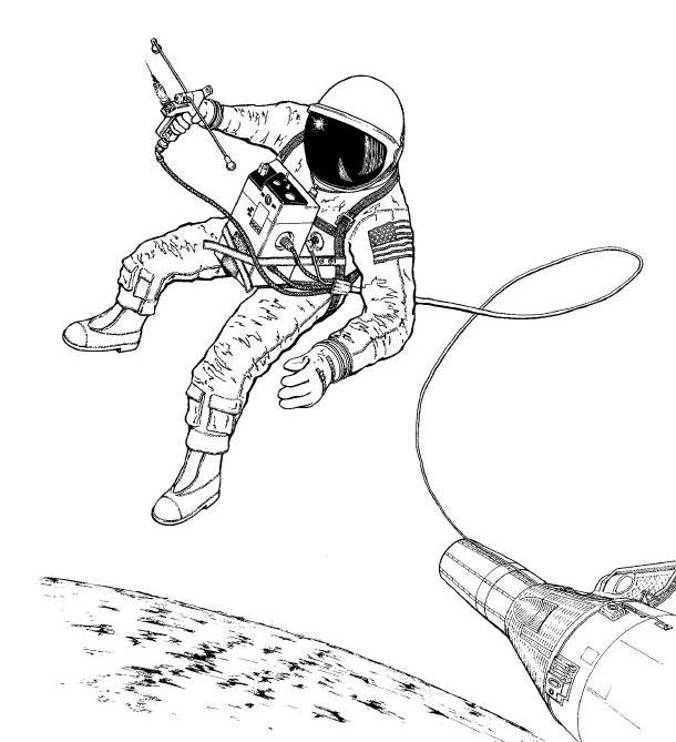
The Extra-vehicular Life Support System (ELSS) is the primary component of the EVA System on each spacecraft mission. The ELSS provides environmental control and supplies the necessary electrical and tether connections to support the pilot during the entire EVA. The ELSS consists basically of a chest pack, umbilical and electrical jumper. The ELSS umbilical is modified for spacecraft 10 and 11 to include a nitrogen hose to support propellant to the Hand Held Maneuvering Unit (HHMU). The HHMU is used to maneuver through space. It provides forward or reverse thrust as required. Typical use of EVA equipment is illustrated in the Figure 16-1.
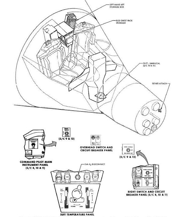
EVA support provisions consist of handrails, handholds, footrest, lights and tether attach points. These aid the pilot in maneuvering to the rear of the adapter and in donning the back pack or performing experiments in that area. Figure below illustrates the typical location of EVA equipment and support provisions.
Typical Locations of EVA Equipment and Support Provisions
The ELSS provides suit pressurization and environmental control
during EVA. Oxygen, from the spacecraft primary oxygen supply, is
supplied to the ELSS chest pack via the umbilical. The umbilical oxygen
attach point is located on the center pedestal in the spacecraft cabin.
Oxygen flow to the umbilical is controlled by the REPRESS valve on the
suit temperature panel. On spacecraft
missions utilizing a back pack, a limited oxygen supply in the back pack
replaces the spacecraft oxygen supply to permit farther excursions from
the spacecraft.
In addition to supplying oxygen to the chest pack, the umbilical provided voice communications and telemetry information, as well as a tether restraint. The modified ELSS umbilical used on spacecraft 10 and 11 also includes a propellant hose for the HHMU. The electrical jumper provides a single connecting point for the chest pack and pressure suit to the umbilical.
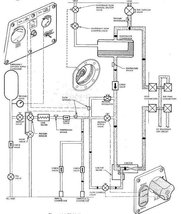
Oxygen Loop - Normal Operation
Oxygen enters the chest pack at the spacecraft
UMBILICAL 02 CONNECTOR or the 02 CONNECTOR. The connectors are
self-sealing quick disconnects. In either case the oxygen is supplied
through check valves to a flow control valve.
The Figure
Below is a
functional diagram of the ELSS chest pack and the
Figure below
illustrates its physical construction and external controls and
indicators.
Oxygen flow to the suit loop is manually controlled by the 02 FLOW
SELECTOR valve. The selector valve has three positions: OFF, MEDIUM
(restricted flow), and HIGH (full open). A push-to-turn motion is
required when changing the valve position. The valve handle and valve
position indications are illuminated for use during darkness. The
selector valve is adjusted to give maximum comfort
Oxygen enters the suit loop at the ejector. The
ejector supplies the means of circulating the flow through the suit loop.
The energy of the expanding high-pressure oxygen (92 psia) from the
selector valve provides the required energy for circulation of the
low-pressure (3.7 psia) gas from the evaporator-condenser. The oxygen
entering the ejector is heated by two i0 watt heaters connected in
series. One of the heaters is wrapped around the ejector throat and the
other is wrapped around the inlet line to the ejector. The heaters are
energized when power is applied to the chest pack.
Suit pressure is maintained at 3.7 psia by the suit outflow valve which vents a portion of the exhausted suit gas overboard. In addition to maintaining Suit pressure, the suit outflow valve accomplishes two additional functions: sufficient carbon dioxide is vented to maintain a safe level within the suit loop and a portion of the heat load is removed with the vented exhausted suit gas. The remaining exhausted suit gas enters the evaporator-condenser to be cooled. The evaporator-condenser is a temperature-controlled heat exchanger. Cooling is accomplished by transferring heat to water stored in the integral metal
ELSS Chest Pack Functional Diagram
and the Figure below illustrates its physical construction and external controls and indicators.
Oxygen flow to the suit loop is manually controlled by the 02 FLOW
SELECTOR valve. The selector valve has three positions: OFF, MEDIUM
(restricted flow), and HIGH (full open). A push-to-turn motion is
required when changing the valve position. The valve handle and valve
position indications are illuminated for use during darkness. The
selector valve is adjusted to give maximum comfort
Oxygen enters the suit loop at the ejector. The
ejector supplies the means of circulating the flow through the suit loop.
The energy of the expanding high-pressure oxygen (92 psia) from the
selector valve provides the required energy for circulation of the
low-pressure (3.7 psia) gas from the evaporator-condenser. The oxygen
entering the ejector is heated by two i0 watt heaters connected in
series. One of the heaters is wrapped around the ejector throat and the
other is wrapped around the inlet line to the ejector. The heaters are
energized when power is applied to the chest pack.
Suit pressure is maintained at 3.7 psia by the suit outflow valve which vents a portion of the exhausted suit gas overboard. In addition to maintaining Suit pressure, the suit outflow valve accomplishes two additional functions: sufficient carbon dioxide is vented to maintain a safe level within the suit loop and a portion of the heat load is removed with the vented exhausted suit gas. The remaining exhausted suit gas enters the evaporator-condenser to be cooled. The evaporator-condenser is a temperature-controlled heat exchanger. Cooling is accomplished by transferring heat to water stored in the integral metal wicks of the heat exchanger. As the gas is cooled the water vapor in the exhausted suit gas condenses and is separated and removed with evaporant wicks by capillary action. The condensed water vapor is passed through the evaporant wicks to the evaporative heat sink. The evaporative heat sink uses the condensed water vapor as a coolant thereby reducing the initial amount of water which must be stored in the heat sink.
The outlet temperature of the gas leaving the
evaporator-condenser is controlled by the EVAPORAT FLOW CONTROL valve. A
temperature sensor at the evaporator-condenser outlet controls the
operation of the EVAPORAT FLOW CONTROL valve to maintain the temperature
at a nominal 45 degrees Fahrenheit. An increase in outlet gas
temperature opens the flow control valve, lowering the boiling point of
the stored water, thus allowing greater heat dissipation in the heat
exchanger. The EVAPORANT FLOW CONTROL valve is shut off until the ELSS
is in operation to prevent loss of the water in the heat sink. If suit
temperature falls to an uncomfortable
level during operation the valve may be closed.
Oxygen Loop - Emergency Operation
There are three conditions that are considered as emergencies. These conditions are: loss of external oxygen supply pressure, low suit pressure, and heat exchanger failure. Each of these three conditions is cause for aborting the EVA. The first two conditions are automatically compensated for; while the third, which is not as critical, requires manual action by the pilot. In the event the external pressure falls below 67 +/- 10 psig (reference to ambient conditions), the emergency pressure reducer automatically actuates suit loop. The BYPASS-NORMAL valve is the push-to-open and push-to-close type. Valve position is illuminated for use during darkness.
The electrical portion of chest pack consists of
a temperature control and oscillator module, oscillator and light
controller module, battery, relay, Electrical Operation The electrical
portion of chest pack consists of a temperature control and oscillator
module, oscillator and light controller module, battery, relay, heaters,
and associated switches and indicators. The
Figure
Below is a schematic
of the chest pack electrical components. heaters, and associated
switches and indicators.
The Figure is a schematic of the chest pack
electrical components.
Chest Pack Electrical Components
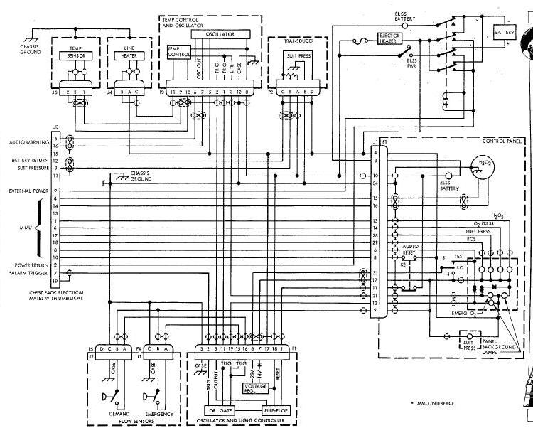
The chest pack operates from battery power or
external power from the spacecraft supplied through the umbilical.
During normal operation external power is utilized. A control relay in
the chest pack is used to select internal or external power. The relay
is energized through the umbilical and supplies external power to the
chest pack when the spacecraft ELSS PWR circuit breaker
is closed. When the relay is de-energized battery power is utilized and
the EIZS PWR indicator on the chest pack instrument panel illuminates.
The battery is the silver-zinc alkaline type using potassium hydroxide as the electrolyte. The battery consists of a group of series-parallel cells connected to provide a nominal load voltage of 24 vdc. Regardless of the power used, the chest pack circuits are not powered until the battery power switch, located underneath the access door on the chest pack, is placed in the ON position.
The oscillator and light controller module consists of a voltage regulator and a logic control circuit. The voltage regulator supplies the necessary 28 vdc and 14 vdc regulated voltages. The logic control circuit consists of a flip-flop and an OR gate. The OR gate obtains trigger inputs from the suit pressure regulator and emergency oxygen flow sensors. Upon receipt of one of the trigger inputs, the gate causes the flip-flop to change states and provide an output to the audio oscillator in the temperature control and oscillator module. The alarm can be reset by pressing the AUDIO pushbutton on the control panel which causes the flip-flop to reset.
The temperature control and oscillator module provides control for the emergency oxygen line heater and the audible and visible warning devices. The emergency oxygen line heater is controlled by the temperature control circuitry obtaining inputs from the emergency oxygen temperature sensor and emergency oxygen flow sensor. When the temperature sensor indicates a temperature below 45 degrees Fahrenheit, and a trigger sigal from the emergency oxygen flow sensor exists, the temperature control circuit allows power to be supplied to the line heater. When the temperature at the sensor exceeds 45 degrees Fahrenheit, the lye heater is deactivated. A signal representing a temperature in excess of 45 degrees Fahrenheit and an emergency oxygen flow signal have to be present before the line heater is activated. The EMERG 02 light is also illuminated by the emergency oxygen flow signal. The oscillator is activated by the outer from the flip-flop of the oscillator and light controller and will supply an audible alarm to the pilots headset and to the spacecraft via the umbilical.
The suit-pressure regulator flow sensor signal, in addition to triggering the OR gate of the oscillator and light controller, is used to illuminate the SUIT PRESS indicator light is returned to the spacecraft for transmission as telemetry information. The pressure transducer is a variable reluctance transducer with an output of 0 to 5 vdc with a sensed pressure of 2.5 to 5 psig.
The wrap-on heaters at the ejector provides 20 watts of power to maintain the suit loop inlet temperature at 45 +/- 10 degrees Fahrenheit. When the battery switch is placed in the ON position, power is applied to the wrap-on heaters.
The panel illumination lights are turned on and off by the battery switch. A three position switch (TEST, DIM, BRIGHT) controls the intensity of the panel lights and the emergency indicator lights. In the TEST position, the panel lights, emergency indicator lights, and the warning alarm audio oscillator are tested. The voltage regulator provides the reduced voltage for the low intensity position of the light switch.
The following light indicators on the instrument panel are not operational unless the experimental back pack is connected: H202, RCS, 02 PRESS, and FUEL PRESS. The H202 pressure indicator is operational when either of the back packs are connected.
HAND HELD MANEUVERING UNIT OPERATION
The HHMU (Figure Below) provides the necessary propulsion required to maneuver in space. The HHMU has two tractor nozzles and a larger pusher nozzle. The HHMU provides two pounds of thrust in the positive or braking direction. The pusher nozzle is attached to the major assembly and is used to supply the braking thrust. The two tractor nozzles are on arms which extend out on each side. This positions the nozzles for thrusting in the positive or forward direction.
Hand Held Maneuvering Unit Diagram
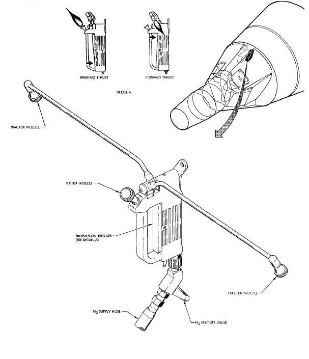
The trigger is pivoted in the center so the tractor nozzles or the pusher nozzle can be controlled with one hand. Squeezing the lower end of the trigger supplies nitrogen to the pusher nozzle and squeezing the upper end of the trigger supplies nitrogen to the tractor nozzles.
The propulsion gas for the HHMU is provided by two bottles of gaseous nitrogen that are mounted in the adapter equipment section. The gas is routed to the adapter skin through metal tubing. A quick disconnect connector and a lever shutoff valve are located on the outside of the adapter and can be reached by opening a small door on the spacecraft skin.
The ELSS chest pack is 18 by 10 by 6 inches and weighs 42 pounds when fully charged. Operating devices on the chest pack used by the pilot include four valves, three switches, two meters, seven indicators, and five connectors. The chest pack housing is molded from fiberglass with a volar finish.
When in use, the chest pack is positioned on the pilots chest (occupying an area from above the thighs to below the chin), and the control panels are readily visible and accessible. The chest pack is held in place by a self-adhering web belt attached to the pints personal harness. The belt ends are laid across strips of the same self-adhering, web-belt material affixed to the chest pack.
Two dual oxygen connectors are prodded with the chest pack to permit continuous oxygen flow to the pilots pressure suit during the egress and ingress preparation procedures. The dual connectors are stowed in the left hand aft stowage container.
ELSS 25 FOOT UMBILICAL AND ELECTRICAL JUMPER
The 25 foot umbilical (Figure Below) is an aluminized Mylar and nylon covered assembly that contains the pilots oxygen supply hose, electrical leads and restraint tether.
ELSS 25 Foot Umbilical and Electrical Jumper
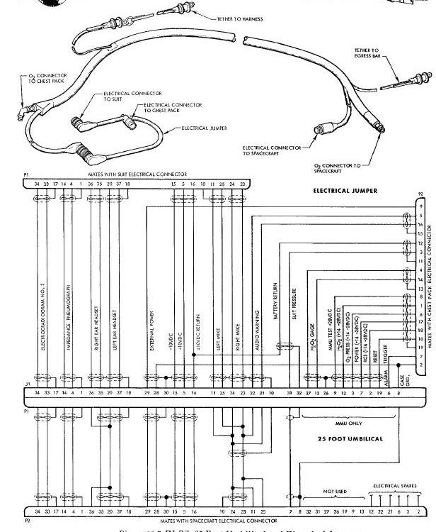
The restraint tether consists of a flat nylon ribbon with a minimum breaking strength of 900 pounds. The tether is connected by snap rings to the right egress bar, located at the forward end of the right hatch opening, and to the D-ring on the pilots harness.
Electrical leads through the umbilical are wrapped around the oxygen hose and carry the bio-med instrumentation and communication signals, and spacecraft power to the chest pack. The umbilical is protected in passing over the hatch opening by an umbilical cord guard.
The oxygen supply hose routes spacecraft primary oxygen to the chest pack. It connects to the disconnect on the suit temperature panel in the spacecraft cabin. The oxygen supply hose is disconnected when the back pack is connected. Oxygen is supplied from the supply tank contained in the back pack.
The electrical jumper provides a single connecting point between the pressure suit and chest pack to the umbilical. The electrical jumper interconnects the signals passing between the chest pack, pressure suit, and spacecraft.
The 25 foot umbilical, electrical Jumper, and umbilical cord guard are stowed in the left hand aft stowage container. The 25 foot umbilical, electrical Jumper, and umbilical cord guarcl are used on spacecraft 8, 9 and 12 missions.
The 50 foot umbilical (Figure Below) is an aluminized Mylar and nylon covered assembly that contains the pilots oxygen supply hose, HHMU nitrogen hose, electrical leads and restraint tether.
ELSS 50 Foot Umbilical Diagram
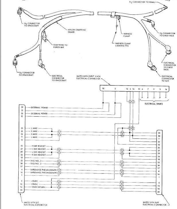
The restraint tether consists of a flat nylon ribbon with a minimum breaking strength of 900 pounds. The tether is connected by a snap ring to the egress bar in front of the right seat and by a harness clamp to the pilots harness.
Electrical leads through the umbilical are wrapped around the hoses and carry the bio-med instrumentation and communication signals. The cabling monitors an electrocardiogram and impedance pneumograph. Communications are established through a left and right microphone and a left and right earphone. Electrical power is supplied in + 10 vdc and -10 vdc along with power for chest pack operation. The umbilical is protected in passing over the hatch opening by a nylon chaffing guard. The oxygen supply hose connects to the oxygen disconnect on the suit temperature panel in the spacecraft and to the UMMBILICAL 02 CONECTOR on the chest pack. The nitrogen hose connections are the quick disconnect aft of the pilots hatch and the HHMU.
The 50 foot umbilical is stored in the left hand footwell stowage pouch. The 50 foot umbilical is used on spacecraft 10 and 11 missions.
The HIHMU provides the necessary propulsion required to maneuver in space. The HHMU is stowed in the left hand aft stowage container. The HHMU is used with the 50 foot umbilical on spacecraft 10 and 11.
The HHMU is constructed of fiberglass reinforced with polyester resin. The HHMU is approximately 11 inches long, 6 inches wide, and 1 inch thick. A pivoted trigger controls the operation of the two valves. The pusher nozzle is mounted on the main body of We HHMU. The two tractor nozzles are on 14 inch arm assemblies which swivel away from the forward end of the HHMU.
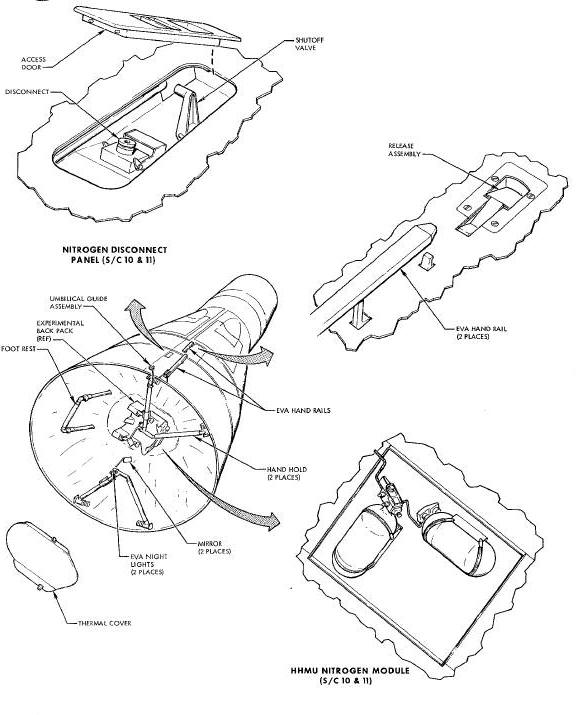
The gaseous nitrogen module (Figure above) is bracket mounted in the spacecraft adapter section. The module consists of two bottles, a pressure regulator, and fill valve. Nitrogen from the bottles is routed to a quick disconnect and shutoff valve located aft of the right hatch by a quarter inch metal tubing.
An access door (Figure above) protects the disconnect and valve during the launch phase. The door is opened by compressing the spring latch assembly. Movement of the door past the vehicle position disengages the hinges for removal.
Each nitrogen bottle will hold up to 438 cubic inches of gaseous nitrogen providing a system capacity of 879 cubic inches, which represent 11.5 pounds of nitrogen (10.75 pounds of the nitrogen is usable for the pilot). The nitrogen is stored at a pressure 5000 to 5500 psig and is regulated to 120 +10/-15 psig by a built-in regulator on the bottle. The pressure at the HHMU will be approximately 100 psig. The system has sufficient capacity for a little over five minutes of continuous usage.
The two EVA handrails are located along the top of the adapter and aid the pilot in maneuvering from the spacecraft cabin to the rear of the adapter. The handrails are illustrated in Figure 16-9.
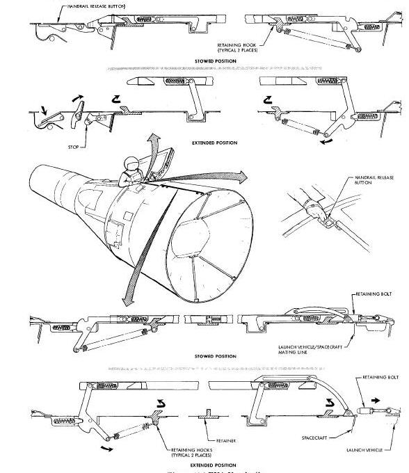
Launch vehicle-spacecraft separation releases the handrail on the adapter equipment section. The handrail is held in the stowed position by a release pin. The release pin is physically attached to the launch vehicle. At separation, the release pin is pulled away with the launch vehicle allowing the handrail to move slightly aft. This allows the handrail to clear the spacecraft retain-ing hooks and self-extend by spring force. Upon full extension the handrail is locked in the extended position.
The forward handrail is extended manually by the pilot when he depresses the release button. Depressing the release button releases the stop and allows the handrail to move slightly forward. This forward movement allows the handrail to clear the retaining hooks emd self-extend by spring force.
An umbilical guide (Figure above) is located at the rear of the handrail on the adapter equipment section. The umbilical guide assembly prevents damage to the umbilical in passing over the edge of the adapter. The umbilical guide assembly is extended when the handholds and footrest in the adapter are extended.
The handholds and a footrest are located in the adapter on spacecraft 8, 9, 11, and 12 missions. These provide a means for the pilot to hold on and remain in the adapter to don the back pack (on spacecraft mission 8, 9 and 12) or perform experiments. The figure above illustrates the handholds and foot rest.
The handholds and footrest are retracted prior to use and are self-extended by spring action. On missions utilizing a back pack, the handholds are held in the retracted position by the thermal covering which protects the back pack. On missions without a back pack, a retaining bar is used.
The handholds and footrest are extended when the INDEX EXTEND-POD EJECT switch in the cabin is positioned to POD EJECT. The switch is located on the right switch and circuit breaker panel (Figure above). The switch controls two guillotines which sever the cables holding the handholds and footrest in the retracted position. A mechanical latch locks them in position. On spacecraft 9 and 12 the control switch is labeled INIEX EXTEND-EVA BARS EXT.
A light is installed on each handhold to illuminate the adapter area during the dark side of the revolution. The lights are controlled by the EXT LTS switch on the right switch and circuit breaker panel. The lights are illustrated in the Figure above.
A mirror is attached to each handhold to allow the pilot to observe the back pack during the donning procedure. The mirrors may be positioned as required by the pilot. Figure 16-2 illustrates the physical location of the mirrors.
The back packs are attached to the spacecraft by means of a retaining bolt which passes through a guillotine. After the back pack is donned by the pilot, the command pilot positions the BACK PACK-DEPLOY switch (located on the main instrument panel) to the DEPLOY position. This actuates the guillotine and severs the retaining bolt releasing the back pack.
E
ELSS - Extra-vehicular Life Support System (ELSS)
EVA - Extra-Vehicular Activity (EVA)
H
HHMU - Hand Held Maneuvering Unit (HHMU)