HORIZON SENSOR SYSTEM
SYSTEM DESCRIPTION
Horizon Sensor Scanner Head Diagram
Horizon Sensor Electronic Package Diagram
Horizon Sensor System Functional Block Diagram
Azimuth Drive Loop Block Diagram
Signal Processing Loop Block Diagram
Horizon Sensor Power Supply Block Diagram
Horizon Sensor Single-Axis Positor Diagram
HORIZON SENSOR SYSTEM
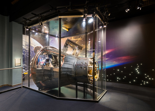
The Horizon Sensor System (Figure Below) consists of a sensor head, an electronics package and their associated controls and indicators. The system is used to establish a spacecraft attitude reference to earth local vertical and generates error signals proportional to the difference between spacecraft attitude and a horizontal attitude. Attitude error signals can be used to align either the spacecraft or the inertial platform to earth local vertical. The system has a null accuracy of O.1 degree and is capable of operating at altitudes of 50 to 900 nautical miles. When the system is operating in the 50 to 550 nautical mile altitude range, measurable spacecraft attitude error +/- 14 degrees. When spacecraft attitude errors are between 14 and 20 degrees, the sensor output becomes non-linear but the direction of its slope always corresponds with the slope of the attitude error. When spacecraft attitude errors exceed 20 degrees, the system may lose track. Two complete systems are installed on the spacecraft. The second system is provided as a backup in case of primary system malfunction.
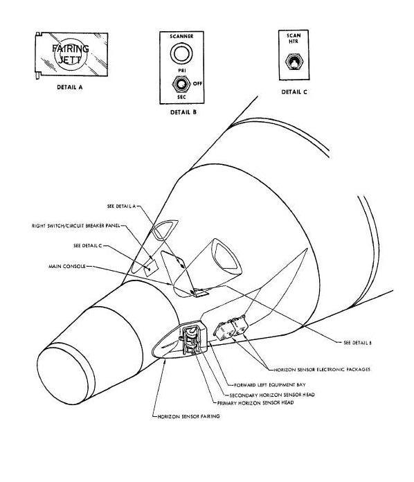
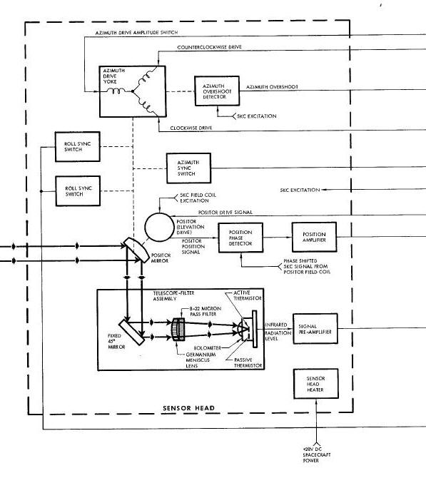
The sensor head (Figure Below) contains equipment required to scan, detect and track the infrared gradient between earth and space, at the horizon. The sensor heads are mounted on the left side of the spacecraft and canted 14 degrees forward of the spacecraft pitch axis. Scanning is provided about the azimuth axis by a yoke assembly and about the elevation axis by a positor (mirror positioning assembly). Infrared detection is provided by a bolometer and tracking by a servo loop which positions the Positor mirror.
Horizon Sensor Scanner Head Diagram
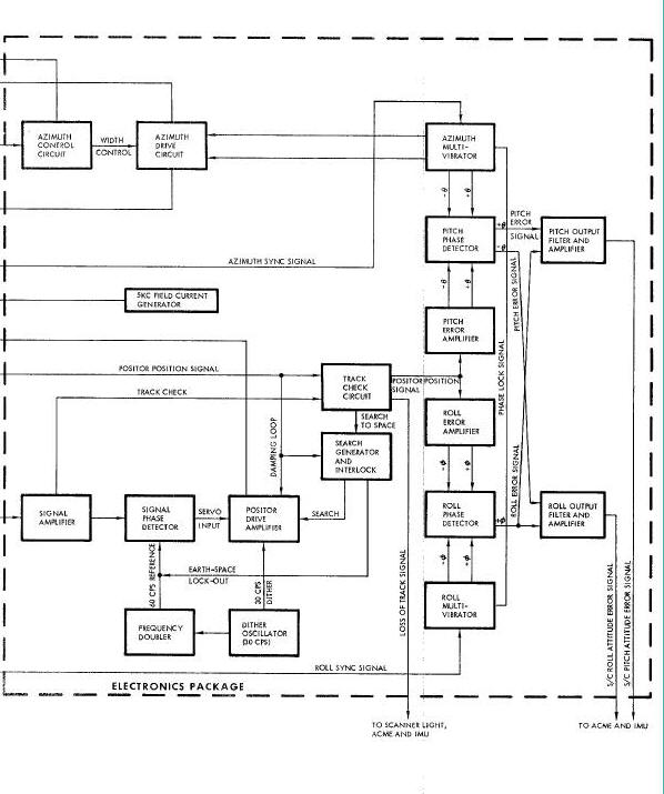
The electronics package (Figure Below) contains the circuitry required to provide azimuth and elevation drive signals to the sensor head and attitude error signals to spacecraft and platform control systems. Electrical signals from the sensor head, representing infrared radiation levels and optical direction, are used to generate elevation drive signals for the Positor. Signals are also generated to constantly drive the azimuth yoke from limit to limit. Attitude error signals are derived from the constantly changing Positor position signal when the system is tracking.
Horizon Sensor Electronic Package Diagram
The primary Horizon Sensor System is energized
during pre-launch by pilot initiation of the SCAN HTR and SCANNER
PRI-OFF-SEC switches. Immediately after staging the pilot presses the
JETT FAIR switch, exposing the sensor heads to infrared radiation.
Initial acquisition time (the time required for the sensor to acquire
and lock-on the horizon) is approximately 120 seconds; reacquisition
time is approximately 10 seconds. The system can be used any time
between staging and retrograde section separation. At retrograde section
separation plus 80 milliseconds the sensor heads are automatically
Jettisoned, rendering the system inoperative.
Operation of the Horizon Sensor System depends on receiving, detecting and tracking the infrared radiation gradient between earth and space, at the horizon. To accomplish the above, the system employs infrared optics, infrared detection and three closely related servo loops. A functional block diagram of the Horizon Sensor System is provided in the Figure below.
Horizon Sensor System Functional Block Diagram
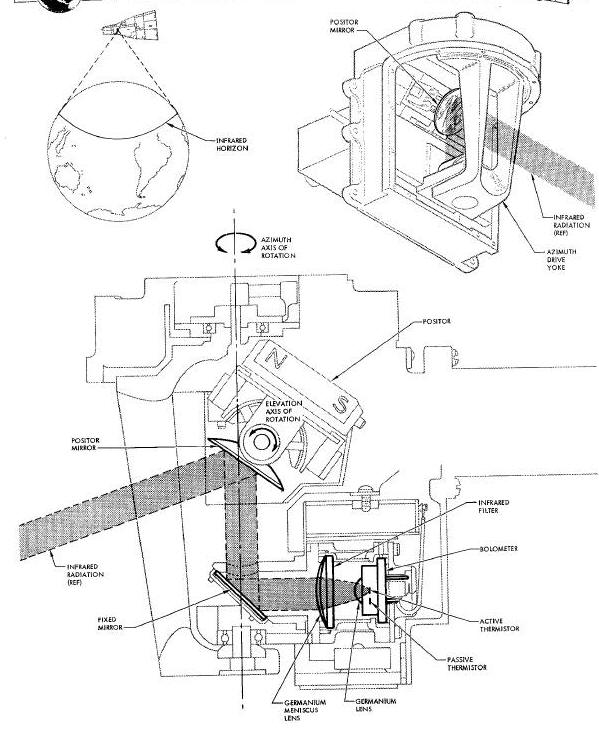
Infrared optics (Figure
Below) consists of a Positor, a telescope-filter assembly and an
azimuth drive yoke. All of these components are located in the sensor
head. The Positor has a movable mirror which is used to position the
system field of view about the horizon. Radiation is reflected by the
Positor mirror into the telescope-filter assembly. A fixed mirror, in
the telescope-filter assembly, directs infrared radiation into the
telescope. The telescope-filter assembly contains a germanium meniscus
objective lens, an infrared filter and
a geranium-immersed thermistor bolometer. The objective lens is used to
direct all the infrared radiation, reflected by the mirrors, on the
germanium immersion lens of the bolometer. The infrared filter is used
to eliminate radiation of undesired frequencies. The filter has a band
pass of 8 to 22 microns (80,000 to 220,000 angstroms). The germanium
immersion lens focuses the infrared radiation on an immersed thermistor.
The horizon sensor field of view is deflected
through 160 degrees (+/_80) in azimuth and 70 degrees (12 up and 58
down) in elevation by rotating the Positor mirror. The Positor is
rotated in azimuth by a drive yoke. Rotation is about an axis which runs
through the center of the infrared ray bundle on the surface of the
Positor mirror. The yoke is driven at a one cycle per second rate by
circuitry in the electronics package. The center of the azimuth scan is
14degrees forward of the spacecraft pitch axis. This Is due to the
mounting of the scanner heads. Elevation deflection is provided by the
Positor which tilts the Positor mirror as required to search for or
track the horizon. The rate at which the Positor tilts the mirror is a
function of the mode of operation (track or search). In search mode, the
Positor mirror moves at a two cps search rate plus a 30 cps dither rate.
In track mode, the Positor mirror moves at a 30 cps dither rate, plus,
if there is any attitude error, a one or two cps track rate. The one or
two cps track rate depends on the direction of
spacecraft attitude error.
Infrared radiation is detected by the germanium-lmmezsed thermistor bolometer. The bolometer contains two thermistors (temperature ensltive resistors) which are part of a bridge circuit. One of the thermistors (active) is exposed to infrared radiation from the horizon. The second thermistor (passive) is located very near the first thermistor but it is separated from infrared radiation. Radiation from the horizon is sensed by the active thermistor which changes resistance and unbalances the bridge circuit. The unbalanced bridge produces an output voltage which is proportional to the intensity of the infrared radiation. If only one thermistor were used, the bridge would also sense temperature changes caused by conduction or convection; to prevent this, a passive (temperature reference) thermistor is used.
The passive thermistor changes resistance the same amount as the active thermistor, for a given ambient temperature change, keeping the bridge balanced. The passive thermistor is not exposed to infrared radiation and allows the bridge to become unbalanced when the active thermistor is struck by radiation from the horizon.
The three servo loops used by the Horizon Sensor System are: the track loop, the azimuth drive loop and the signal processing loop. Some of the circuitry is used by more than one servo loop and provides synchronization.
The track loop (Figure Below) is used to locate and track the earth horizon with respect to the elevation axis. Two modes of operation (search and track) are used in the track loop. The search mode is selected automatically when the system is first energized and used until the horizon is located. After the horizon is located and the signal built up to the required level, the track mode is automatically selected.
The search mode is automatically selected by the
system any time the horizon is not in the field of view. The purpose of
the search mode is to move the system line of sight through its
elevation scan range until the horizon is located. (The system line of
sight is moved by changing the angle of the positor mirror. ) When the
system is initially energized, the Positor position signal is used to
turn on a search generator. The generator produces a two cps ac search
voltage which is applied to a summing Junction in the Positor
drive amplifier. A second signal (30 cps dither) is also applied to the
summing junction. (The dither signal is present any time the system is
energized. ) The search and dither voltages are summed and amplified to
create a Positor drive signal. This drive signal is applied to the drive
coils of the Positor causing it to tilt the Positor mirror. The dither
portion of the signal causes the mirror to oscillate about its elevation
axis at a 30 cps rate and through an angle which represents
approximately four degrees change in the
line of sight. The search portion of the signal will drive the Positor
mirror up to an angle which represents a llne of sight 12 degrees above
the spacecraft azimuth plane. During the up scan (earth to space) a
lock-out signal is applied to the servo loop to prevent the system from
locking on to false horizon indications. When the positive limit of the
search voltage (12 degrees up) is reached, the voltage changes phase and
the system begins to scan from 12 degrees up to 58 degrees down. During
the down scan (space to earth), the lock-out signal is not used and the
system is free to select track mode if the horizon comes within the
field of view.
The bolometer output (indication of infrared radiation) is used to determine when the horizon comes within view and to initiate the track mode of operation. As the system line of sight crosses the horizon (from space to earth), a sharp increase in infrared radiation is detected by the bolometer. The bolometer bridge output now produces a 30 cps ac signal. (The 30 cps is caused by the dither signal driving the line of sight back and forth across the horizon.) The bolometer bridge output is amplified and applied to the track check circuit. When the 30 cps signal reaches the track check circuit, it causes a tracking relay to be energized indicating that the horizon is in the field of view. Contacts of the relay apply a bias to the search generator, turning it off and removing the search voltage from the Posltor drive signal. This places the system in the track mode of operation.
The bolometer output signal is used to determine the direction of the horizon from the center of the system line of sight. A Positor drive voltage of the proper phase is then generated to move the system line of sight until the horizon is centered in the field of view. The bolometer output signal is phase detected with respect to a 60 cps reference signal. The 60 cps signal is obtained by doubling the frequency output of the dither oscillator. Since both signals (30 cps dither and 60 cps reference) come from the same source, the phase relationship should be a constant. However, when the horizon is not in the center of the field of view, the bolometer output is not symmetrical. The time required for one complete cycle is the same as for dither but the zero crossover is not equally spaced, in time, from the beginning and end of each cycle. The direction the zero crossover is shifted from center depends on whether the horizon is above or below the center of the field of view. The phase detector determines the direction of shift (if any) and produces dc pulses of the appropriate polarity. The output of the signal phase detector is applied to the Positor drive amplifier where it is summed with the dither signal. The composite signal is then amplified and used to drive the Positor mirror in the direction required to place the horizon in the center of the field of view.
A pickup coil, wound on the permanent magnet portion of the Positor drive mechanism, produces an output signal which is proportional (in phase and amplitude) to the position of the Positor mirror. This Posltor position signal is phase detected to determine the actual position of the mirror. The detector output is then amplified and used for two purposes in the track loop: to activate the search generator when the tracking relay is de-energized and as a rate damping feedback to the Positor drive amplifier. (When the tracking relay is energized, it biases the search generator to cutoff. )
The azimuth drive loop (Figure Below) provides the drive voltage, overshoot control and synchronization required to move the system llne of sight through a 160 degree scan angle at a one cps rate. The azimuth drive loop consists of an azimuth overshoot detector, azimuth control circuit, azimuth multivibrator, azimuth drive coils and an azimuth drive yoke.
Azimuth Drive Loop Block Diagram
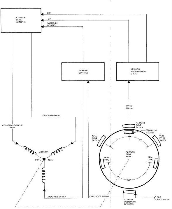
The azimuth overshoot detector does not, as the name implies, detect the azimuth scan overshoot. It instead detects when the azimuth drive yoke reaches either end of its scan limit. The detector is a magnetic pickup, located near the azimuth drive yoke and excited by a 5 kc signal from the field current generator. Two iron slugs, mounted on the azimuth drive yoke, pass very near the magnetic pickup when the yoke reaches the scan limit. The slugs are positioned 160 degrees apart on the yoke to represent each end of the scan. When one of the iron slugs passes near the magnetic pickup, it changes the inductance and causes the 5 kc excitation signal to be modulated with a pulse. Since the azimuth scan rate is one cps and the modulation occurs at each end of the scan, the overshoot pulse occurs at a two pps rate. Output of the overshoot detector is applied to the azimuth control circuit.
The azimuth control circuit generates two types of azimuth control voltages (coarse and fine) based on the azimuth overshoot signal. The azimuth overshoot detector output is rectified, filtered, peak detected and integrated to develop a dc control voltage proportional to the amplitude and width of theovershoot pulse. This control voltage serves two purposes: to provide continuous, fine control of the azimuth drive pulse and, when the control voltage reaches a high enough level (indicating a large overshoot), provide a coarse (step) control of the reference voltage on the azimuth drive coils. The fine control is obtained by applying the control voltage, as a bias, to the azimuth drive amplifier. The coarse control is obtained by energizing a relay, which switches the reference voltage on the azimuth drive coils when the control voltage reaches a high enough level. The level at which the relay energizes is determined by a zener diode which breaks down and biases a relay driver into conduction. The relay driver then energizes a relay which switches the voltage on the reference winding of the azimuth drive coils.
The azimuth multlvibrator provides the direction control signal for the azimuth drive. The multivlbrator is synchronized by pulses from the azimuth sync switch. The sync switch is located next to the azimuth drive yoke and is closed each time the yoke passes through the center of its 160 degree scan. The switch produces a two pps output which is used to switch the state of the multlvlbrator. The multivihrator then produces a one cps square wave signal which is synchronized with the motion of the azimuth drive yoke. The positive half of the square wave controls the azimuth drive in one direction and the negative half controls the drive in the other direction. Output of the multlvibrator is applied to the azimuth drive amplifier.
The azimuth drive amplifier adjusts the width of multivibrator output pulses to control the azimuth drive yoke. The output pulse width, from the drive amplifier depends on the amount of control voltage (bias) provided by the azimuth control circuit. When the amount of azimuth yoke overshoot is large, the control voltage is high and the output pulse width is narrow. As the amount of overshoot decreases, the control bias decreases and the output pulse width increases. This provides a continuous, fine control over the drive pulse and consequently the amount of azimuth drive yoke travel.
The azimuth drive coils convert drive signals into a magnetic force. The coils are mounted next to, and their magnetic force exerted on, the azimuth drive yoke. The direction of magnetic force is determined by which drive coil is energized.
The azimuth drive yoke is a means of
mechanically moving the system line of sight through a scan angle. (The
Positor is mounted inside the azimuth drive yoke and the rotation is
around the center line of the infrared ray bundle on the Positor
mirror.) The azimuth drive yoke is spring loaded to its center position
and the mass adjusted to give it a natural frequency of one cps. Mounted
on the yoke are two iron slugs and a permanent magnet. The iron slugs
are used in conjunction with the azimuth overshoot detector
mentioned previously. The magnet is used to activate sync switches
located next to the drive yoke. The switches synchronize
mechanical motion of the yoke with electrical signals. The function of
the azimuth sync switch was described in the azimuth multivlbrator
paragraph, The function of the two roll sync switches will be described
in the phase detectors paragraph of the signal processing loop.
The signal processing loop (Figure Below) converts tracking and azimuth scan information into attitude error signals. (The error signals can be used to align the spacecraft and/or the Inertial Guidance System to the earth local vertical. ) A complete servo loop is btained by utilizing two other spacecraft systems (Attitude Control and Maneuver Electronics and the Propulsion System). Attitude error signals, generated by the Horizon Sensor System are used by the Attitude Control and Maneuver Electronics (ACME) (in the horizon scan mode) to select the appropriate thruster (or thrusters) and generate a fire command. The fire command causes the Propulsion System to produce thrust in the desired direction. As the thrust changes spacecraft attitude, in the appropriate direction, the attitude error signals decrease in amplitude. Then the spacecraft attitude comes within preselected limits (0 to -10 degrees in pitch and +/- 5 degrees in roll), as indicated by error signal amplitude, the ACME stops generating fire commands. As long as the spacecraft attitude remains within the preselected llmits, it is allowed to drift freely. If the attitude exceeds the limits, thrust is automatically applied to correct the error.
Signal Processing Loop Block Diagram
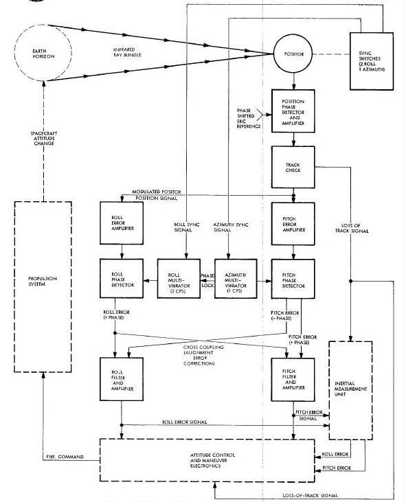
An indirect method of controlling spacecraft attitude (on spacecraft 5, 6 and 8 through 12) with the horizon sensor involves a third spacecraft system (Inertial Guidance). This method can be used when it is desired to fine align the inertial measurement unit. Horizon sensor attitude error signals are now used to continuously torque gyros in the inertial platform, aligning them to the local vertical. The platform attitude error signals are then used by the ACME (in the platform mode) to generate fire commands for the Propulsion System. Using this method of attitude control, the spacecraft is held to within +/- 1.1 degrees of the platform attitude in all three axes.
The inertial platform can also be aligned by the horizon sensor without using a servo loop. To align the platform without a closed servo loop, the pilot must manually maintain spacecraft attitude as near null as possible. (The horizon sensor attitude error signals are most accurate when the spacecraft is in a horizontal attitude with respect to the earth surface.) Attitude error signals are then used to torque platform gyros and have no direct effect on spacecraft attitude.
The Horizon Sensor System also provides a loss of track indication to both the ACME and Inertial Guidance System. The signal is used to prevent the ACME or platform from aligning to a false horizon. The loss of track signal is also used to illuminate the SCANNER light on the pedestal s informing the pilot that the system is not tracking. (Spacecraft attitude must be held within + 20 degrees of the horizontal for the system to track.)
Horizon sensor tracking geometry (Figure Below) is composed of the elevation angles (0) generated by the track loop and the azimuth angles (0) generated by the azimuth drive loop. Angles are compared in time and phase to generate an error signal proportional to the elevation angle change with respect to the azimuth scan angle.
Horizon Sensor Tracking Geometry
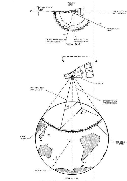
As explained in the track loop paragraph, the system will lock on in elevation and track the earth horizon. A dither signal causes the Posltor to move the system llne of sight about the horizon at a 30 cps rate. The track loop will move the Posltor mirror such that the horizon is always in the center of the dither pattern. It was also explained, in the azimuth drive loop paragraph, that the system line of sight is continuously moved through a 160 degree azimuth scan angle at a one cps rate.
As explained in the track loop paragraph, the system will lock on in elevation and track the earth horizon. A dither signal causes the Posltor to move the system line of sight about the horizon at a 30 cps rate. The track loop will move the Posltor mirror such that the horizon is always in the center of the dither pattern. It was also explained, in the azimuth drive loop paragraph, that the system line of sight is continuously moved through a 160 degree azimuth scan angle at a one cps rate.
When the spacecraft is in a horizontal attitude, the azimuth scan has
no effect on the elevation angle of the Positor as it tracks the
horizon. If the spacecraft is in a pitch up attitude, the elevation
angle (0) will decrease as the azimuth angle (0) approaches 80 degrees
forward and increase as angle 0 approaches 80 degrees aft. If the
spacecraft is in a pitch down attitude, the elevation
angle will increase as the azimuth angle approaches 80 degrees forward
and decrease as the azimuth angle approaches 80 degrees aft. This
produces a one cps pitch error signal which is superimposed on the SO
eps Positor dither. If the spacecraft has a roll right attitude, the
elevation angle will increase as the azimuth angle approaches either
limit and decrease as the azimuth angle approaches zero from either
llmit. If the spacecraft is In a roll left attitude the elevation angle
will decrease as the azimuth angle approaches either limit and increase
as the azimuth angle approaches zero from either limit. This produces a
two cps error signal which is superimposed on the 30 cps Positor dither.
The Positor position phase detector compares the Positor pickoff signal with a 5 kc reference to determine the angle of the Positor mirror. (The mirror angle will be change at a 30 cps dither rate, plus, if there is any spacecraft attitude error, a one and/or two cps error signal rate.) he phase detector output is then amplified and applied to the track check circuit.
The track check circuit determines when the horizon is in the field
of view. If the horizon is in the field of view, the track check circuit
energizes a relay. Contacts of this relay connect the Positor position
signal to the pitch and roll error amplifiers. A second relay in the
track check circuit, energized when the system is not tracking, provides
a loss of track indication to the inertial measurement
unit and the ACME. The loss of track signal is 28 volts dc obtained
through the ATT IND CNTL-LDG circuit breaker and switched by the track
check circuit.
In order to obtain individual pitch and roll attitude error outputs, error signal separation must be accomplished. This function is performed by two error amplifiers. The Positor position signal input to the error amplifiers is a composite 30 cps dither, one cps pitch error and two cps roll error signal. The pitch error amplifier is tuned to one cps and selects the pitch error signal only for amplification. The roll error amplifier is tuned to two cps and selects the roll error signal only for amplification. Each amplifier then amplifies and inverts their respective signals, producing two outputs each. The outputs are 180 degrees out of phase and of the same frequency as their input circuits were tuned. Output of each error amplifier is coupled to its respective phase detector.
Phase detectors compare the phase of pitch and roll error signals
with one and two cps multivibrator reference signals to determine the
direction of attitude error. The multivibrators are synchronized with
motion of the azimuth drive yoke by three sync switches. Two sync
switches, located at 57 degrees on either side of the center position of
the yoke synchronize the roll multivibrator with the motion of the yoke
and set its frequency at two cps. The sync switches close each time the
yoke passes, in either direction, producing four pulses for each cycle
of the yoke. Each time a pulse is produced it changes the state of the
multivibrator resulting
in a two cps output. The azimuth multivibrator operates in the same
manner except that it only has one sync switch, located at the center of
the drive yoke scan, resulting in a one cps output frequency. The
azimuth multivibrator also provides a phase lock signal to the roll
multivibrator to assure not only frequency synchronization but correct
phasing as well. The phase detectors themselves are actually reed
relays, two for each detector, which are energized alternately by their
respective multivibrator output signals. Contacts of these relays
combine the two input signals in such a manner that two full wave
rectified output signals are produced. The polarity of these pulsating
dc outputs indicates the direction and the amplitude indicates the
amount of attitude error about the horizon sensor pitch and roll axes.
Since the sensor head was mounted at a 14 degree angle with respect to
the spacecraft, the mounting error must be compensated for. Electrical
rotation of the horizon sensor axes, to correspond with spacecraft axes,
is accomplished by cross coupling a portion of the pitch and roll error
signals.
The output amplifier-filter removes most of the two and four cps
ripple from the rectified attitude error signals and amplifies the
signals to the required level. The identical pitch and roll operational
amplifiers, used as output stages for the Horizon Sensor System, are
highly stable and have a low frequency response. The output signal
amplitude is four tenths of a volt for each degree of spacecraft
attitude error The signals are supplied to the ACME for spacecraft
alignment and to the inertial measurement unit for platform alignment.
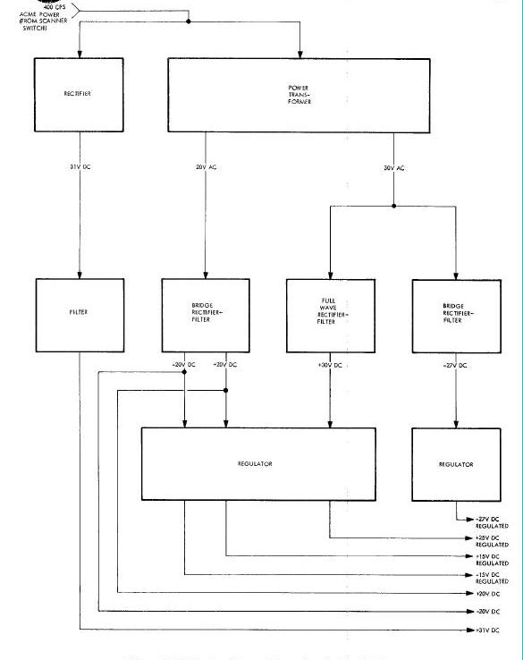
Horizon sensor power (Figure
Below) is obtained from the 28 volt dc spacecraft bus and the 26
volt ac, 400 cps ACME power. The 28 volt dc power, supplied through the
SCAN HTR switch, is used to maintain temperature in the sensor head and
as power for the SCANNER lamp. Sensor head heaters are thermostatically
controlled and operate any time the SCAN RTR switch is on. The 26 volt
ac, 400 cps ACME power is provided by either the IGS or ACME inverter,
depending on the position of the ac POWER selector. The 26 volt ac is
used to produce seven different levels of dc voltage used in the horizon
sensor. One of the voltages (31 volts dc) is obtained
by rectifying and filtering the 26 volt ac input. The remaining six
levels are obtained by transforming the 26 volts to the desired level,
then rectifying, filtering and regulating it as required. The minus 27
volts dc output is used to excite one side of the bolometer bridge. The
other side of the bridge is excited by plus 25 volts dc. Plus 25 volts
dc is also used for transistor power in the error amplifiers. The 31
volt dc unregulated output is Used as excitation for the azimuth drive
yoke. The remaining four voltages (+15, -15, +20, -20) are all used for
transistor power in the various electronic modules.
Horizon Sensor Power Supply Block Diagram
The Horizon Sensor System (Figure Above) consists of two major units and five minor units. The minor units are: three switches, an indicator light and a fiberglass fairing. The three switches are mounted on the control panels for pilot actuation. The indicator light is mounted on the pedestal and, when Illuminated, indicates a loss of track. The fiberglass fairing is dust proof and designed to protect the sensor heads, which it covers, from accidental ground damage or thermal damage during launch. The two major units are: the sensor head and the electronics package.
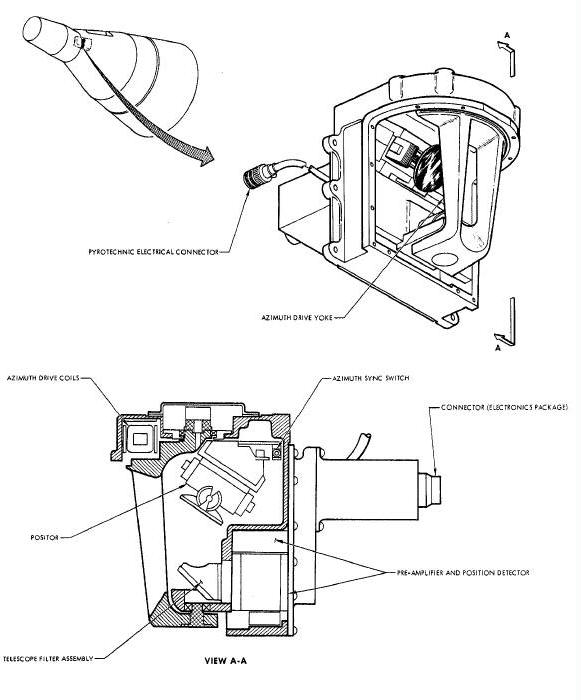
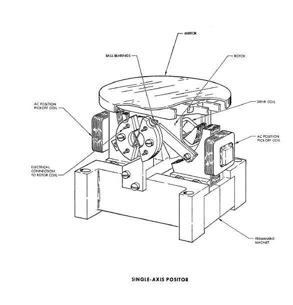
The sensor head (Figure Above) is constructed from a magnesium casting and contains a Positor, a telescope-filter assembly, a signal preamplifier, a position detector, an active filter and an azimuth drive yoke. The Positor (Figure Above) is a mirror positioning assembly designed to position a mirror about its elevation axis. The mirror is polished beryllium and is pivoted on ball bearings by a magnetic drive. The Positor also includes a position pickoff coil for determining the angle of the Positor mirror.
Horizon Sensor Single-Axis Positor Diagram
The telescope-filter assembly (see
Figure Above) contains a fixed mirror, a germanium meniscus lens, an
infrared filter and a germanium immersed thermistor bolometer. The fixed
mirror is set at a 45 degree angle to reflect radiation from the Positor
mirror into the telescope. The germanium meniscus objective lens of the
telescope is designed to focus incoming infrared radiation on the
bolometer. The infrared filter, located immediately behind the objective
lens, Is designed to pass infrared radiation in the 8 to 22 micron
range. The germanium immersed thermistor bolometer contains a
culminating lens and two thermistors. The culminating lens directs all
incoming radiation on one of the thermistors. The two thermistors are
bonded to the rear of, and effectively immersed in, the culminating
lens. Both thermistors are identical; however, one of the thermistors
(active) is located at the focal point of the culminating lens. The
other thermistor (passive) is located to one side of the focal point.
The passive thermistor is used as an ambient
temperature reference and does not react to direct infrared radiation.
The signal preamplifier is a low noise, high gain, four stage, direct coupled transistor amplifier. The preamplifier is made in modular form and potted in epoxy for thermal conductivity and protection from shock and vibration.
The position detector is a five kc phase detector designed to determine the position of the Posltor mirror. The circuit produces a voltage which is proportional to the angle of the Positor mirror. Output of the detector is a dc voltage which varies at the same rate as the Positor mirror moves. The detector is made in modular form and potted in epoxy for thermal conductivity and protection from shock and vibration.
The azimuth drive yoke provides a means of moving the Positor mirror about its azimuth axis. The yoke is magnetically driven and pivots on ball bearings. The Positor is mounted inside the azimuth drive yoke and is rotated through an azimuth scan angle of 160 (+80) degrees by the yoke. The azimuth axis of rotation is through the center line of the infrared ray bundle on the surface of the Positor mirror. Drive coils, located directly in front of the yoke, supply magnetic impulses to drive the yoke. Mounted on the edge of the yoke (see Figure Above) are two iron slugs and a permanent magnet. The iron slugs are used to induce an overshoot signal in the azimuth overshoot detector. The permanent magnet is used to synchronously close contacts on three sync switches, mounted around the periphery of the yoke.
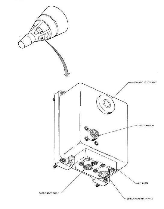
The electronics package (Figure Above) contains the circuitry necessary to control the azimuth yoke and Positor in the sensor head, as well as process attitude error signals. The package also contains a dc power supply and a five kc field current generator. The solid-state circuitry is made in modular form and potted in epoxy for thermal conductivity and protection from shock and vibration.