Landing Systems
Parachute Landing System Diagram
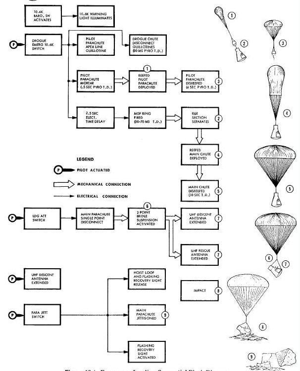
Landing System Sequential Block Diagram
Emergency Landing Sequential Block Diagram
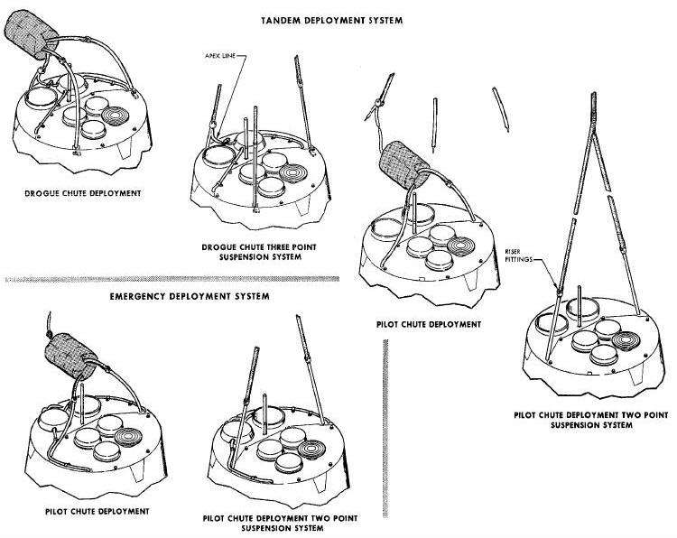
Tandem and Emergency Deployment Operation Diagram
Drogue Parachute Assembly Diagram
Drogue Parachute Mortar Assembly
Drogue Parachute Deployment Bag
Pilot Parachute Assembly Diagram
Pilot Parachute Mortar Assembly
Pilot Parachute Deployment Bag
MAIN PARACHUTE AND RISER ASSEMBLY
Main Parachute and Single Point Suspension System Diagram
Main Parachute and Two Point Suspension System Diagram
Main Parachute Deployment Bag and Container Assembly
Main Parachute Bridle Assembly
Main Parachute Support Assembly
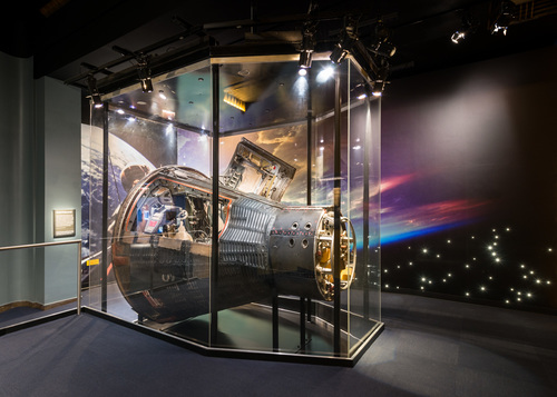
The parachute Landing System (Figure
Below) provides a safe rate of descent to return the re-entry module
to the earth's surface and furnishes the proper attitude to the landing
module for a water impact. A system of three parachutes in series is
utilized for stabilizing and retarding the velocity of the spacecraft
from 50,000 feet. During the final stage of descent, the main parachute
suspension is changed from a single point to a two point system in order
to achieve a more favorable attitude for a water landing. The Landing
System consists of three parachute assemblies (a drogue parachute
assembly, a pilot parachute assembly, and a main parachute assembly),
two mortar assemblies, reefing cutters, disconnect assemblies, riser
assemblies, and attaching hardware. The entire
Landing System, with the exception of the aft bridle leg and disconnect
assembly, is located in the rendezvous and recovery section of the
spacecraft. The
Figure Below illustrates the sequence of events from re-entry to
impact in block diagram form. This
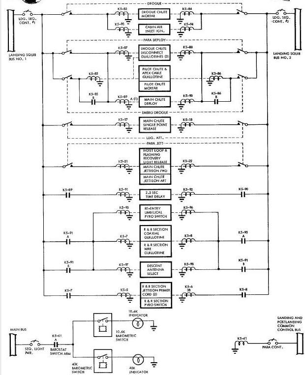
Figure Below
illustrates the electrical sequence of the landing system.
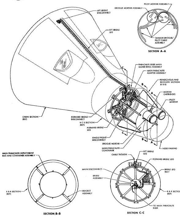
Parachute Landing System Diagram
Landing System Sequential Block Diagram
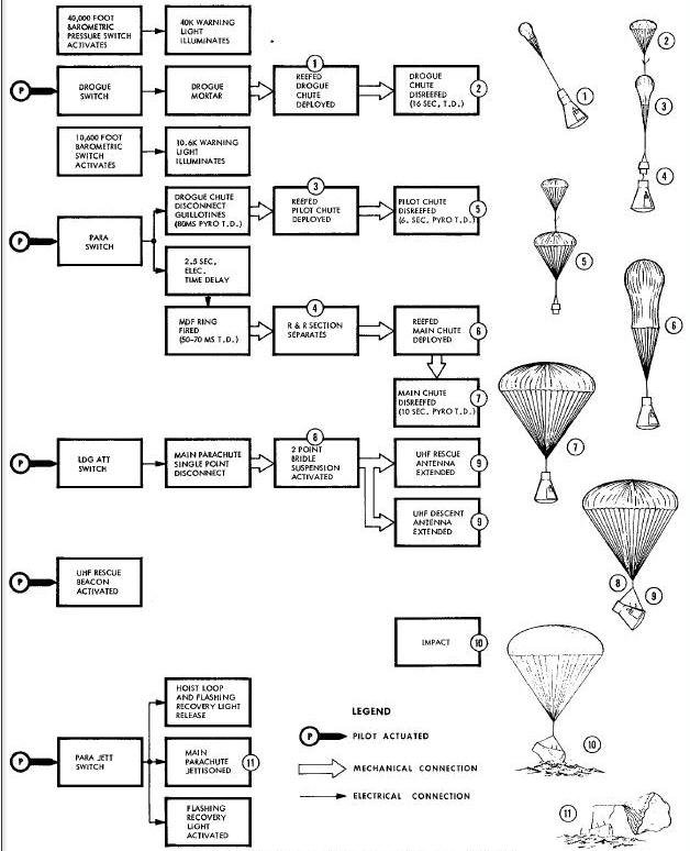
Prior to re-entry, the landing and postlandlng common control electrical buses are armed by positioning the LANDING switch to ARM. This also applies power to the two barometric pressure switches for illumination of the 10.6K and 40K warning indicators.
When the altimeter indicates an altitude of 50,000 feet, the HI-ALT DROGUE switch is manually activated. The drogue switch energizes two single pyrotechnic cartridges in the drogue mortar. The drogue mortar deploys the reefed drogue parachute. The parachute is reefed to limit the opening shock load. Sixteen seconds after deployment, two pyrotechnic reefing cutters disreef the drogue parachute. The drogue parachute stabilizes the re-entry module.
At approximately 10,600 feet, the PARA switch is activated. The PARA switch fires the three drogue cable guillotines and sets a 2.5 second time delay to the MDF ring detonators. After the drogue riser legs have been cut, the drogue parachute pulls away from the re-entry module extracting the pilot parachute from the pilot mortar tube with the apex line. When deployed, the pilot parachute is reefed to limit the initial shock load. Two lanyard initiated pyrotechnic reefing cutters disreef the pilot chute six seconds after deployment. 2.5 seconds after the pilot chute has been deployed, the MDF ring fires separating the rendezvous and recovery section from the landing vehicle. The pilot parachute functions to decelerate the re-entry module, remove the rendezvous and recovery section, and deploy the main parachute.
As the landing module falls away from the rendezvous and recovery section, the main parachute is deployed in a reefed condition. The main parachute is disreefed by three lanyard initiated pyrotechnic reefing cutters ten seconds after deployment. The two decelerations provided by the main parachute divide the retarding shock load. After the main parachute has been disreefed, the manually operated LDG ATT switch is actuated to channel the single point suspension system to a two point suspension system. The two point suspension system provides a more favorable attitude for impact. As soon as the landing module contacts the ocean surface, the PARA JETT switch is activated. The PARA JETT switch energizes the forward and aft bridle disconnects releasing the main parachute. Upon completion of the landing, the landing module is prepared for transmitting data and recovery information through the erected recovery antenna.
In the event the drogue parachute does not deploy or deploys improperly, the PRE-MAIN 10.6K switch is actuated. The closure of this switch fires the three drogue cable guillotines, the apex line guillotine, and the pilot parachute mortar and starts the 2.5 second time delay to the MDF rings. The pilot mortar deploys the pilot parachute in a reefed condition. From this point, the emergency sequence of events is exactly the same as used during a normal landing. The Figure Below illustrates the emergency sequence of events in block diagram form, and This Figure Below illustrates the emergency deployment.
Emergency Landing Sequential Block Diagram
Tandem and Emergency Deployment Operation Diagram
The drogue parachute assembly (Figure Below) stabilizes the re-entry module and deploys the pilot parachute. This assembly consists of an 8.3 ft diameterconical ribbon parachute with twelve 750-pound tensile strength suspension lines. A three legged riser assembly attaches the parachute assembly to the rendezvous and recovery section.
Drogue Parachute Assembly Diagram
When initially deployed, the drogue chute is reefed to 43 percent of the parachute diameter in order to reduce the opening shock load. Sixteen seconds after deployment, two pyrotechnic reefing cutters disreef the drogue chute. Initiation of the PARA switch fires three cable guillotines located at the base of the three riser legs. As the drogue chute pulls away from the rendezvous and recovery section, an apex line, which is attached to one of the riser legs, extracts the pilot parachute from the pilot mortar tube. The drogue parachute remains attached to the pilot parachute during the entire descent of the rendezvous and recovery section of the re-entry module.
Drogue Parachute Mortar Assembly
The drogue parachute mortar assembly stores and protects the drogue parachute during flight and deploys the drogue parachute when activated by the HI-ALT DROGUE switch. An insulated metal pan retains the parachute in the mortar tube which has a diameter of 7.15 inches and is 9.12 inches long. The breech assembly, located at the base of the mortar tube, contains two electrically actuated pyrotechnic cartridges and an orifice. The cartridges generate gases which enter the mortar tube through the orifice and eject the drogue parachute and sabot.
The drogue mortar sabot is an aluminum cup located in the base of the mortar and functions to eject the drogue parachute with a piston llke action. In order to insure the most effective ejection, the sabot is fastened to the base of the orifice by a frangible bolt, and an O-ring, located near the base of the sabot which contacts the inner wall of the mortar tube to prevent any escape of gases generated by the two pyrotechnic cartridges. When enough pressure to break the frangible bolt has built up, the sabot and parachute are expelled from the mortar tube. After ejection, the sabot remains attached to the parachute bag and aids in stripping the bag from the parachute.
Drogue Parachute Deployment Bag
The drogue parachute deployment bag protects the drogue parachute during deployment and allows for an orderly deployment of the parachute. The bag is fabricated from cotton sateen and nylon. A 0.35 pound aluminum plate, sewn into the top of the bag, aids in stripping the bag from the canopy during the deployment.
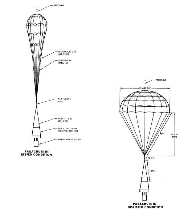
The pilot parachute assembly (Figure
Below) decelerates the re-entry module and removes the rendezvous
and recovery section from the lending module which results in the
deployment of the main parachute. During flight, the pilot parachute
assembly is stowed in the pilot mortar tube. The 18.3 foot diameter
canopy is of the ringsall type having 16 gores and fabricated from 1.1
and 2.25 ounce per
square yard nylon. Sixteen nylon cord suspension lines, which are 17
foot long and have a tensile strength of 550 pounds each, attach the
canopy to the riser assembly. A 10.7 foot long split riser, constructed
of four layers of 2600 pound tensile strength Dacron webbing, holds the
pilot parachute assembly to the rendezvous and recovery section of the
spacecraft. When initially deployed, the pilot parachute is reefed to
11.5 percent in order to limit the opening shock load to 3000 pounds.
Two pyrotechnic reefing cutters disreef the parachute 6 seconds after
deployment. The pilot parachute remains attached to the rendezvous and
recovery section throughout the entire descent.
Pilot Parachute Assembly Diagram
Pilot Parachute Mortar Assembly
The pilot parachute mortar assembly is similar in design and operation to the drogue parachute mortar assembly. During normal operation of the Landing System, this assembly serves only to store and protect the pilot parachute. In the event of a failure in the deployment of the drogue parachute, the pilot parachute mortar can be activated to deploy the pilot parachute by initiation of the PRE-MAIN 10.6 K switch. Actuation of the PRE-MAIN 10.6K switch fires the three drogue cable guillotines, the apex line guillotine, and the pilot parachute mortar. After the pilot parachute has been deployed, the landing is completed through the normal sequence of events. Figure 12-5 illustrates the pilot parachute deployment.
The pilot mortar sabot functions are the same as those of the drogue mortar sabot.
Pilot Parachute Deployment Bag
The pilot parachute deployment bag is similar to the drogue parachute deployment bag in design and use, except for the bag handles attached to the apex line for extraction by the drogue parachute.
MAIN PARACHUTE AND RISER ASSEMBLY
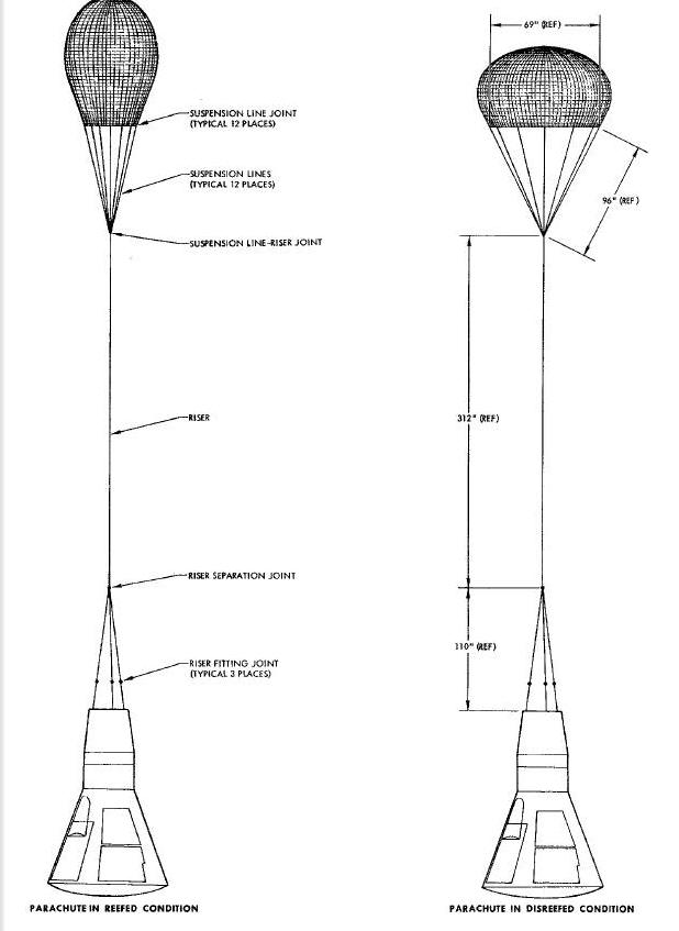
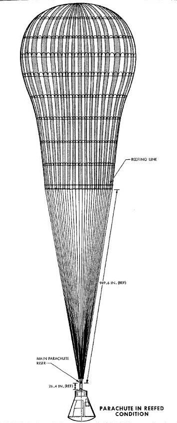
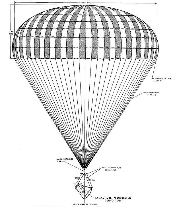
The main parachute (Figure
Below ) is of the ringsail type with a diameter of
84.2 feet. The nylon canopy has seventy-two gores alternating in colors
of international orange and white. Seventy-two suspension lines are
attached to eight legs of a single integral riser. Each suspension line
has a tensile strength of 550 pounds. The 3.25 foot integral riser
consists of eight layers of 5,500
pound tensile strength nylon webbing. The canopy is fabricated from 1.1
and 2.25 ounce per square yard nylon and is designed to operate at a
dynamic pressure of 120 pounds per square foot. However, by reefing the
main parachute, a maximum load of 16,0OO pounds is experienced at
deployment. When initially deployed, the parachute is reefed to 10.5
percent. The disreefed main parachute allows a maximum rate of descent
of 31.6 feet per second for a module weight of 4,400 pounds.
Main Parachute and Single Point Suspension System Diagram
Main Parachute and Two Point Suspension System Diagram
Main Parachute Deployment Bag and Container Assembly
The main parachute deployment bag and container assembly (Figure
Below) stows the maln parachute. This assembly is located in the aft
end of the rendezvous and recovery section of the spacecraft. The
deployment bag is fabricated from a cotton sateen material reinforced
with nylon webbing. In order to insure a full and orderly deployment of
the maln parachute, the suspension lines must be
stretched out prior to the release of the canopy. Therefore, transverse
locking flaps are incorporated in the bag to separate the canopy from
the suspension lines. Four restraining straps hold the deployment bag in
the container until deployment.
The main parachute container is 22.25 inches in diameter and 21.32 inches long. The container is closed on the forward end and is secured to the rendezvous and recovery section by four vertical reinforcing brackets. At deployment, the restraining straps of the deployment bag are unlocked, the risers and suspension lines are extended, and the canopy is pulled from the deployment bag. The deployment bag remains attached to the container by four bag handles.
Main Parachute Bridle Assembly
The main parachute bridle assembly (Figure
Above).provides a two point suspension system in order to achieve
the optimum attitude for a water landing. Two separate bridle straps
constitute the main parachute bridle assembly. The forward bridle strap
is an 85 inch long nylon strap with a looped end connected to the
forward bridle disconnect. Prior to single point release, the forward
bridle is stowed
in the bridle tray (Figure
Above ). The aft bridle is 106 inches long and connects to the aft
disconnect which is located immediately forward of the single point
hoist loop (Figure
Above). Constructed of heat resistant nylon, the aft bridle is
stowed in a trough that extends from the front of the Re-entry Control
System section to the aft disconnect during flight. An insulating cover
shields the aft
strap in the cable trough until the single point suspension is released,
at which time the bridle leg tears through the insulation.
Main Parachute Support Assembly
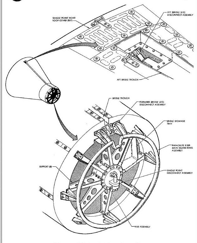
Upon landing in the water, the main parachute is released from the landing module by activation of the PARA JETT switch. This initiates the forward and aft disconnect pyrotechnics and allows the chute to pull away from the landing module.