Guidance and Control
Guidance and Control Functional Block Diagram
Attitude Control and Maneuver Electronics
Gemini Ascent Guidance (Back-Up) Diagram
ATTITUDE CONTROL AND MANEUVERING ELECTRONICS
Attitude Control and Maneuver Electronics
ACME Simplified Block Diagram (Rate Cmd. and Re-entry Rate Cmd. Modes)
ACME Simplified Block Diagram (Horizon Scan Mode)
ACME Simplified Block Diagram (Re-entry Mode)
Re-entry/Rate Command Mode (M5d)
ACME Simplified Block Diagram (Platform Mode)
ATTITUDE CONTROL ELECTRONICS (ACE)
ORBIT ATTITUDE AND MANUVER ELECTRONICS (OAME)
RCS & OAMS Attitude Valve Drivers Diagrams
ACME Maneuver Control-Simplified Block Diagram
Inertial Guidance System
Preparation for Retrograde & Re-Entry
Attitude Display Group (ADG) Diagram
Incremental Velocity Indicator
Internal Platform Gimbal Structure
Attitude Malfunction Detection
Pulse Rebalance Current Supply
Accelerometer Malfunction Detection
Computer Memory Functional Organization
Basic Information Flow Diagram
Instruction Information Flow Diagram
PRO Operation (Inputs; when A9=1)
PRO Operation (Inputs; when A9=O)
Executor Routine Program Flow Diagram
Digital Command System Subroutine
Instrumentation System Subroutine
Inertial Computer Platform Interface Diagram
Computer- Platform Electronic Interface
Computer - Power Supply Interface Diagram
Auxiliary Computer Power Unit (ACPU)
Manual Data Insertion Unit (MDIU)
Computer TRS Interface Diagram
Computer DCS Interface Diagram
Computer-Radar Interface Diagram
Attitude Display/Attitude Control and Maneuver Electronics (ACME)
Computer-Attitude Display/ACME Interface Diagram
Computer-Autopilot Interface Diagram
Computer-ATM-PCDP Interface (S/C 8 thru 12 Only)
Pilots' Control and Display Panel (PCDP)
Computer - PCDP Interface Diagram
Incremental Velocity Indicator (IVI)
Computer-IVI Interface Diagram
Aerospace Ground Equipment (AGE)
Computer-AGE Interface Diagram
Manual Data Keyboard Data Flow
Manual Data Readout Data Flow Diagram
ATM Write Electronics Block Diagram
INCREMENTAL VELOCITY INDICATOR
Incremental Velocity Indicator Diagram
Incremental Velocity Indicator Front Panel Diagram
The Guidance and Control System provides the Gemini Spacecraft with the capability to maneuver in space, control its attitude in relation to the earth's surface. and effect a safe re-entry. It also provides back-up launch vehicle guidance during ascent and control of certain target vehicle functions during rendezvous procedures.
Spacecraft attitude can be controlled about three axes: pitch, roll, and yaw. A mode select switch permits selection of either automatic or manual control. An attitude hand controller, located for use by either pilot, is used for manual attitude control.
Translation control is provided along the longitudinal, vertical, and lateral spacecraft axes. Either of two maneuver hand controllers may be used for manual translation control. No provision is made for automatic control.
Three types of target vehicles are provided for the rendezvous missions: the Agena, the Rendezvous Evaluation Pod (REP), and the Augmented Target Docking Adapter (ATDA). Certain functions within the Agena or the ATDA can be controlled through the Command Link of the Guidance and Control System.
In rendezvous
spacecraft, the Guidance and Control System is made up of eight
individual systems or subsystems. They are:
a. Attitude Control and Maneuver Electronics (ACME)
b. Inertial Guidance System (IGS)
c. Horizon Sensors.
d. Rendezvous Radar System
e. Command Link
f. Rendezvous Evaluation Pod (REP)
g. Time Reference System (TRS)
h. Propulsion System
Guidance and Control Functional Block Diagram
The various guidance and control systems are all functionally related. The functional relationship between each of the systems is illustrated in Figure Above.
Attitude Control and Maneuver Electronics
The Attitude Control and Maneuver Electronics system converts input signals to thruster firing commands for the Propulsion System. Input signals to ACME are provided by the attitude hand controller, the IGS, or the horizon sensors depending on the mode of operation.
The Inertial Guidance System provides inertial attitude and acceleration information, guidance computations and displays. The inertial attitude and acceleration information is used for computations and display purposes. Computations are used for back-up ascent guidance, rendezvous guidance and re-entry guidance. Displays are utilized by the crew for reference information and as a basis for manual control.
The Horizon Sensors provide a reference to the earth local vertical during orbit. Pitch and roll error signals are supplied to ACME for automatic attitude control and to the IGS for platform alignment.
The Rendezvous Radar provides target range, range rate, and angle information. Target information is used for rendezvous computations and for display purposes. A radar indicator displays target range and range-rate information. Target elevation and yaw angles are selectable for display on the attitude indicator.
The Command Link provides a control capability over the Agena or ATDA target vehicle. Coded commands and transmitted either through the radar or the umbilical, allow the pilot to activate or de-activate the various systems of the target vehicle.
The Rendezvous Evaluation Pod is the target for a simulated rendezvous mission. The pod is carried into orbit in the equipment adapter section of Gemini. Once in orbit, the pod is ejected and its systems activated. A radar transponder and acquisition lights in the pod allow the Gemini pilots to perform rendezvous exercises.
The Time Reference System provides a time base for all guidance and control functions. Time is displayed for pilot reference in both clock and digital form. The TRS also provides timing signals to the computer and the Sequential System.
The Propulsion System provides the thrust required for spacecraft maneuvers. Thrusters are provided for both translational and attitude control. Firing commands for the Propulsion System are provided by ACME.
The functions of the Guidance and Control System are dependent on mission phase. The mission is divided into five phases for explanation purposes. The phases are: pre-launch, launch, orbit, retrograde, and re-entry.
Pre-launch phase is utilized for check-out and programming of guidance and control systems. Parameters required for insertion in the desired orbit are inserted in the computer. The IMU is aligned to the local vertical and the desired launch azimuth. Power is turned on to the various systems, and mode selectors are placed in their launch position. Check-out and parameter insertion are performed in the last 150 minutes prior to launch.
Gemini Ascent Guidance (Back-Up)
Guidance and control from lift-off through SSECO is provided by the booster guidance system. However, in case of booster guidance malfunction the IGS can assume control. Provision is made for either automatic or manual switchover to back-up (Gemini) guidance. Figure Above indicates both methods of switchover and the backup method of controlling the booster during ascent. The IGS monitors attitude and acceleration parameters throughout the launch phase. Ground tracking information Is used to continuously update computer parameters. At SSECO, the remaining velocity required for insertion is displayed. The command pilot will, after separation, use the Propulsion System to increase spacecraft velocity as required for insertion in the desired orbit. Insertion will take place approximately 580 miles down range at an inertial velocity of approximately 25,000 feet per second.
Orbit phase is utilized for checkout and alignment of systems, rendezvous maneuvers and preparation for retrograde and re-entry. Immediately after insertion a series of system checks will be performed to assure the capability of guidance and control systems. Guidance computations and measurements are checked for accuracy against ground tracking information. Systems are updated and aligned by ground command or by the pilot. After completion of system checks, the catch-up and rendezvous maneuvers can be performed. During the final orbit, guidance and control systems are re-aligned in preparation for retrograde and re-entry.
Retrograde phase begins approximately five minutes before retrofire. The computer is placed in re-entry mode and begins collecting data for re-entry computations. The Time Reference System provides indications at TR-256 seconds, TR-30 seconds, and TR. At TR-256 seconds, a minus 16 degree bias is placed on the pitch attitude needle. The Propulsion System is switched from orbit attitude and maneuver to re-entry control. Spacecraft attitude is controlled manually during retrograde. Retrograde acceleration and attitude are monitored by the IGS, and velocity changes are displayed for reference.
Re-entry phase begins immediately after
retrofire. The event timer counts
through zero at retrograde and will be counting down from sixty minutes
during re-entry phase After retrofire, the retrograde adapter and
horizon scanner heads are Jettisoned. Shortly after retrograde, the
pilot orients the space-craft to re-entry attitude (0° pitch, 180 °
roll, 0° yaw). Re-entry attitude is held until the computer re-entry
program starts. At approximately 400,000 feet attitude, the computer
re-entry program starts and the pilot has a choice of manual or
automatic control. For manual control, the pilot selects RE-ENT RATE
CMD. For automatic control, the RE-ENT mode Is utilized. In the
automatic mode, the computer controls
spacecraft roll attitude. For either mode of control, the flight
director is referenced to the computer and indicates computed attitude
commands. The purposes of the computer re-entry program are to control
the point of touchdown and to control re-entry heating. By controlling
the spacecraft
roll attitude and rate, it is possible to change the down-range
touchdown point
ATTITUDE CONTROL AND MANEUVERING ELECTRONICS
The Attitude Control and Maneuver Electronics (ACME) System provides the control circuitry to attain and/or maintain a desired spacecraft attitude or velocity. The ACME accepts signal inputs from the attitude hand controller, horizon sensors, platform, or computer; processes the signal(s); and applies a firing command to the appropriate Propulsion System solenoid valves. ACME is composed of four separate subsystems: Attitude Control Electronics (ACE), Orbit Attitude and Maneuver Electronics (OAME), a power inverter and two identical rate gyro packages. The ACE, power inverter and rate gyro packages are installed in the center bay of the re-entry module. The OAME package is located in the equipment section of the adapter. Total weight of the ACME System is approximately 40 pounds.
Attitude Control and Maneuver Electronics
The ACME provides the capability of automatic or manual attitude control, with seven separate, selectable modes of operation. The horizon sensor, the inertial platform or the computer provide the reference for automatic modes of operation. The attitude hand controller provides the input signals for manual modes of attitude control. The maneuver hand controller supplies signals to the maneuver solenoid valves for translational maneuvers.
The ACME provides
attitude control, automatic or manual, during all flight phases of the
spacecraft mission. Rate gyro inputs to ACE are used to dampen
spacecraft attitude rates. Signal inputs are modified by ACME logic and
converted to firing commands for the Propulsion System.
The ACME functional modes of the control are horizon scan, rate command, direct, pulse, re-entry rate command, re-entry, and platform. Each mode provides a different signal input (or combination of inputs) to be processed by ACE for routing to Re-entry Control System (RCS) or OAME solenoid valve drivers. The modes of control are separated into two basic types; automatic attitude control modes (horizon scan, re-entry and platform) and manual attitude control modes (rate command, direct, pulse and re-entry rate command). Display information from control panel indicators is used as reference when manual control modes are utilized. Reference information is supplied by guidance and control subsystems and consists of the following: attitude, attitude rates, bank angle and roll commands (from the attitude display group), velocity increments (from the incremental velocity indicator), and range and range rate (from the radar indicator). The control panels also contain the control switches necessary for selection of ACME power and logic circuits and attitude control mode, along with selection switches for the various ACME redundant options.
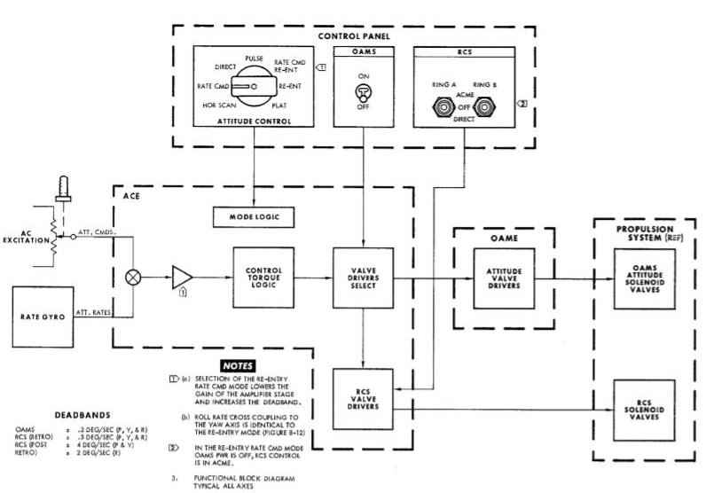
Commands or error signals from the computer, platform, horizon sensors, rate gyros and attitude hand controllers are converted by the ACE into thruster firing commands. The firing commands are routed by a valve driver select system to the RCS or the Orbit Attitude Maneuver System (OAMS) attitude solenoid valve drivers.
Signal inputs to the ACE are of three types : ac attitude signals, dc attitude signals, and ac attitude rate signals. These signals are selected and distributed by ACE mode logic switching circuits. Selected signals are channeled through the proportional circuitry which amplifies, sums and demodulates the signal inputs into vdc analog output. Horizon sensor (dc attitude) signals are converted to ac prior to entering the proportional circuitry. The analog signals are then converted by control torque logic switch circuitry to a positive or negative discrete, the output consisting of either positive or negative thruster firing commands. These commands are routed from the valve driver select system to the RCS (ring A and/or ring B) valve drivers, or to the OAMS attitude valve drivers for a firing command to the appropriate thruster valves. Zener diode spike suppression circuits limit the voltages generated across the solenoid valves during current interruptions.
Spacecraft attitude may be manually controlled by use of the attitude hand controller and a visual reference. Controller outputs are rate, pulse or direct command signals, (plus a hand controller position output to telemetry) depending upon the control mode selection. Output signals are produced by positive or negative handle movements from the centered position. Rate signals produced are proportional to the amount of control displacement from a center deadband. Direct and/or pulse signals are produced when the hand controller is displaced past a preset threshold or deadband. Pulse signals trigger a pulse generator in ACE to produce a calibrated on time. The control handle must be returned to a neutral position before another single pulse can be commanded. Details of each control mode may be found in the MODE OPERATION paragraph.
ACME Simplified Block Diagram (Rate Cmd. and Re-entry Rate Cmd. Modes)
The RCS direct mode is selectable as an alternate means of manually firing the RCS thrusters, and by-passes the ACE. The DIRECT position of each of the RCS RING A or RING B switches provides a circuit ground to 12 attitude hand controller RCS direct switches. The ground is then applied directly to the required thruster solenoid valves through appropriate hand controller displacements. This RCS mode of operation is intended for backup or emergency control only.
Translational maneuvers of the spacecraft in the horizontal, longitudinal and vertical planes may be commanded by either of the maneuver hand controllers. Displacement of a hand controller, from the centered or neutral position in any of the six translational directions produces a direction command to the respective solenoid valves.
The function of the rate gyro package is to sense angular rate about the pitch, yaw and roll axes of the spacecraft and provide an output signal proportional to that sensed rate. Selection of certain control modes provides gyro inputs to ACE for angular rate damping. Additional information concerning the rate gyros may be found in the paragraph under SYSTEM RATE GYR0 PACKAGE.
The power inverter provides the ACME and horizon sensors with ac power. Spacecraft dc power is converted to 26V, 400 cps (The IGS inverter provides the primary source of ac excitation). The ACE inverter is utilized when the Inertial Measurement Unit (IMU) is off. Additional information regarding the power inverter may be found in the paragraph under SYSTEM UNITS POWER INVERTER PACKAGE.
Control of spacecraft attitude is accomplished through the selection of seven functional control modes. Each control mode is utilized for a specific purpose or type of ACME operation in conjunction with various mission phases. Each mode provides either automatic or manual spacecraft control through the switching of input signals to ACE. In addition, the mode logic circuits de-energize all unused circuits within the ACE during use of the horizon scan mode to conserve power. Switching is performed by transistors at the signal level and by relays at the power level. The operation of each control mode is explained in the following.
In this mode, thruster firing commands are applied directly to the RCS or OAME attitude solenoid valve drivers by actuation of the attitude hand controller direct switches (Figure Below). Selection of the direct mode applies a bias voltage to a transistor designated ground switch A. Conduction of the transistor completes a circuit to ground which is common to one side of the hand controller direct switches. The transistor remains on as long as the direct mode is selected. Six normally-open switch contacts provide the command signals in the pitch, yaw and roll axes and will close when the hand controller is moved beyond a preset threshold (2.5 degrees) of handle travel. Deflection in the desired direction applies a ground from switch A directly to the valve driver relative to that direction which, in turn, fires the proper thruster(s). Thrusters continue firing as long as the hand controller is displaced beyond the 2.5 degree threshold. This mode of operation is optional at all times.
In this mode, the attitude commands initiated by hand controller displacement fire a single pulse generator in the ACE (Figure Below). The pulse mode logic activates the generator, allowing it to fire for a fixed duration when a pulse command is received. Commands originate every time one of the six normally-open pulse switch contacts of the hand controller is closed. This triggers the generator and applies a bias voltage pulse for a 20 millisecond duration to ground switch A. This ground is then applied to the RCS or 0AME attitude valve drivers, through the actuated hand controller direct switches, as a command for thruster firing. Commands may be initiated in the pitch, yaw or roll axis by moving the control handle in the desired direction beyond a preset threshold (3.5 degrees). Thrusters fire for 20milliseconds each time the handle is displaced beyond S.5 degrees. Tphis mode is optional at all times and will normally be used during platform alignment.
In this mode, spacecraft attitude rate about each axis is proportional to the attitude hand controller displacement from the neutral deadband (Figure Below) (The output remains at zero for displacements less than 1 degree of handle travel, providing a non-operational area or deadband). Command signals, generated by handle displacements, are compared with rate gyro outputs, and when the difference exceeds the damping deadband, thruster firing occurs. Signals originate from potentiometers in the hand controller and outputs are directly proportional to handle displacement. A maximum command signal to ACE produces an angular rate of 10 degrees/second about the pitch and yaw axis and 15 degrees/second about the roll axis.
Automatic, closed-loop stabilization of spacecraft rates is provided by the sensing of angular rates by the rate gyro package. With the absence of hand controller command signals, spacecraft rates about each axis are dampened to within + 0.2 degrees/second with OAME attitude control and to within 0.5 degrees/second with RCS attitude control. Output signals from the rate gyros are used to produce fire commands until the rate signal is within the damping deadband. This mode is optional at all times and will normally be used during translational thrusting or attitude changes.
In this automatic command mode, horizon sensor outputs (pitch and roll) are processed by the ACE to orient and hold the spacecraft within a desired attitude deadband during orbit (Figure Below). Pitch attitude is maintained automatically to within +/-5 degrees of the horizon sensor +/-5 degrees output, and roll attitude is maintained automatically to within +/- 5 degrees of the horizon sensor zero degree null. Control about the yaw axis is accomplished by commands from the attitude hand controller in the same manner as in the pulse mode. Pulse control about the pitch and roll axes is also available to supplement the automatic control. A -5 degree bias voltage is summed with the pitch input to the ACE to maintain the 5 degree pitch down orientation. When the attitude error (pitch or roll) exceeds the 5 degree control deadband, the output of the ACE on-off logic is a pulse firing command. The pulse time is 18 milliseconds and the pulse repetition frequency is dependent upon how much the attitude error exceeds the 5 degree deadband. A lag network in this mode provides a pseudo rate feedback for rate damping without having to use the power-consuming rate gyros.
ACME Simplified Block Diagram (Horizon Scan
Mode)
In this automatic command mode, spacecraft angular rates about the pitch and yaw axes are dampened to within +/-4 degrees/second and to within +/-2 degrees/second about the roll axis (Figure Below). Roll attitude is controlled to within +/-2 degrees of the attitude commanded by the digital computer input to ACE. The computer roll input to ACE consists of either a bank angle attitude command or a fixed roll rate command depending upon the relationship between the predicted touchdown point and the desired touchdown point. Roll to yaw crosscoupling is provided to minimize the spacecraft lift vector.
ACME Simplified Block Diagram (Re-entry
Mode)
Re-entry/Rate Command Mode (M5d)
In this manual command mode, spacecraft rates are controlled by rate commands from the attitude hand controller. With the exception of wider deadbands, the method is identical to the rate command mode with the addition of roll-yaw rate crosscoupling. Angular rate damping about the three axes is identical to the re-entry mode. The computer bank angle and roll rate commands do not automatically control the spacecraft but are provided on the control panel displays as a reference for initiating manual re-entry roll commands.
This attitude control mode is used to maintain spacecraft attitude, in all three axes, with respect to the inertial platform. Spacecraft attitude is held automatically to within 1.1 degrees of the platform attitude. A horizontal attitude, with respect to the earth, can be held if the inertial platform is in the orbit rate or alignment mode of operation. Spacecraft attitude rates are dampened to within + 0.5 degrees/second. The primary purpose of this mode is to automatically hold an inertial spacecraft attitude. This mode is also useful for maintaining spacecraft attitude during fine alignment of the platform.
ACME Simplified Block Diagram (Platform Mode)
The rate command mode of ACME will be utilized for attitude control during all abort modes. Control over the RCS ring A and ring B switches for a mode 2 abort is automatically switched to ACME by the abort sequential relays.
ATTITUDE CONTROL ELECTRONICS (ACE)
The ACE package (Figure Above) weighs approximately 17 pounds, has a removable cover and contains ten removable module boards. These boards make up the ACE logic circuitry and consist of the following: a mode logic board, an ac signal processing board, three axis logic boards, three relay boards, a power supply board (+20, +10, -10 vdc) and a lag network board. These replaceable module boards perform the signal processing for the three-axis control, and convert signal inputs into appropriate thruster firing commands. They also contain the solenoid valve driver circuits for the RCS solenoid valves.
Input signals to ACE are dependent upon altitude or attitude rate requirements of the spacecraft and are used to obtain an attitude or attitude rate correction. A functional schematic of the ACE is shown in Figure Above and is sectioned to show signal processing for each of the three axes. ACE mode logic circuits are represented by the blocks at the left of the figure. The selection of an attitude control mode initiates transistor switching in the logic circuits pertaining to thai mode. The appropriate input signal is then switches into the proper ACE channel for processing. Additional information on mode logic switching may be found in the Mode Logic Switching paragraph.
Proportional circuits consist of the signal
amplifier stages (attitude and rate),
switch amplifiers and the demodulator/filter stages. Attitude and rate
signals
to each of the pitch, yaw and roll channels (with the exception of
horizon sensor signals) are ac and are amplified to operational levels
by the attitude and rate amplifiers. The outputs are summed and fed to
the switch amplifiers. The output of the switch amplifier is coupled to
the demodulator stage where it is converted to a positive or negative dc
analog signal. The dc signal then energizes either the positive or
negative, low-hysteresis transistor switch in the control torque logic
section. The switches for the pitch and yaw axes are held on for a
minimum of 18 milliseconds by the minimum pulse generators. Horizon
sensor dc signals are chopped and amplified by the switch amplifiers
then modulated in the same manner as ac signals.
The valve driver select circuits control power and signal distribution to 0AME and RCS attitude valve drivers. To turn off the OAME control system, power is supplied to de-energized relays. The normally-closed relay contacts forward the power and signal inputs to the OAME. Power may then be amplified to the RCS ring A and/or ring B valve drivers for ECS altitude control. The ring A and ring B RCS valve drivers consist of relays energized by transistor relay drivers.
Transistor switching provides the control for attitude mode signal selections, along with ACE power distribution in the horizon scan mode. These switches are represented by blocks in Figure Below. The logic function for each block is explained in the truth table at the right of Figure Below as being ground or not ground. Figure Below shows how mode control of signal selections is accomplished.
The transistor switches provide a grounded or not grounded condition to attitude signals# by being in a conducting or non-conducting state. Attitude reference and command signals are obtained by selecting the appropriate control mode switch position. This applies a +20 vdc bias voltage to their base of a PNP transistor, biasing it to cut off. This ungrounded state allows the desired signal to be applied to the ACE amplifiers. The mode 1 (direct), land mode 2 (pulse), and one of the M4 (horizon scan) logic switches are PNP transistors, and conduct with the application of +20 vdc, This provides a ground circuit for hand controller commands. The pulse generator signal provides the bias voltage to turn on switch A when in the pulse or orbit modes.
The type signal selected for each mode of control can be determined by
referring to the logic block in each channel and the mode logic table.
The P and I blocks, through mode selections, establish the gain for
rate amplifier stages.
Inputs to the ACE are either in-phase or out-of-phase ae signals (with the exception of the de horizon sensor input). A positive attitude displacement generates an in-phase error signal which, in turn, will command negative thrusting. A negative attitude displacement, generating an out-of-phase signal, will command positive thrusting. By referring to the logic table, it may be seen that the selection of mode 5 provides a computer roll input through the function of logic block DR and is the only attitude signal selected for an input to ACE. A roll attitude error or command signal is fed into the three-stage attitude amplifier. The amplifier output will be used to turn on the appropriate solenoid valve driver. The limiter is used to limit attitude signal amplitude. The output of the three-stage switch amplifier is transformer coupled to either the in-phase or the out-of-phase section of the demodulator stage. The output of the demodulator stage is a full-wave rectified dc signal, which is filtered and energizes either the positive or negative low-hysteresis switch. Energizing the switch provides the ground for the valve drivers. The minimum pulse generator will not allow the solenoid valves to turn off in less than 18 milliseconds, thus assuring a prescribed minimum thruster force. Minimum pulse generators are used in the pitch and roll channels only.
Angular rate and rise command signals are provided by the logic functions of blocks Cp, Cy and Cr through the selection of modes M3, M5, MSD, and M6. Signal gains through the rate amplifiers are varied by the functions of logic blocks Ip, Iy, Ir, Pp, Py, and Pr, with the selection of the re-entry modes or platform mode. Rate signal inputs are used in the ssme manner as attitude signals to control solenoid valves. Roll rate signals are summed with the computer command signal and the proportional output is fed to the switch amplifiers. The function of the logic block MR, with selection of the re-entry modes of control, provides crosscoupling of roll rates into the yaw axis for re-entry control. Roll rate signals are proportionally coupled into yaw. This provides an opposite-phase signal for cancellation of part of the yaw rate command signal for proper stability.
Sensor pitch and roll signals are positive or negative dc and are fed directly to out-of-phase choppers in ACE. A -5 degree pitch bias voltage is summed with the pitch horizon sensor output for pitch down orientation. The output of the chopper will be of a phase opposite the attitude displacement (a positive attitude displacement will result in an out-of-phase output, and a negative attitude displacement will result in an In-phase output). This signal is then amplified and processed by the on-off logic in the same manner as an attitude signal.
The horizon scan mode, in addition to energizing circuits utilized by other modes, energizes the resistance - capacitance lag feedback networks and choppers for either the in-phase or out-of-phase signal. The lag network discharge rate, along with the minimum pulse generator operation, provides anti-hunting control (hunting would result from the slow response of the horizon sensors if no anti-hunt control were used).
The RCS solenoid valve drivers (Figure Below) are relays with normally-open contacts connected between the solenoid valve and the RCS ring switch. They provide a circuit ground when the switch is in the ACME position. The relays are energized by transistor relay drivers which conduct upon receiving thruster firing commands from the control torque logic switches or the attitude hand controller direct switches. Zener diode spike suppression is provided to limit the voltage generated when thruster power is interrupted.
ORBIT ATTITUDE AND MANUVER ELECTRONICS (OAME)
This unit (Figure
Above) weighs approximately 8
pounds, has a removable cover and contains three removable module boards
(2-reley boards end 1-component module board) as well as fixed
components. The replaceable module boards, in conjunction with the fixed
component, function as attitude valve drivers and provide spike
suppression for the maneuver solenoid valves.
Functional Operation
Attitude Commands to the OAME are either positive or negative thruster firing logic commands to the solenoid valve drivers from the control torque logic section of ACE (See Figure Below). Upon receiving command signals, the valve driver transistors will conduct. This provides the circuit grounds to energize the solenoid valves of the propulsion system. Zener diode spike suppression is provided to limit the voltage generated when thruster power js interrupted.
RCS & OAMS Attitude Valve Drivers Diagrams
Maneuver commands originate from either of the two maneuver hand controllers (Figure Below). Translational command signals are obtained by applying a circuit ground through the proper hand controller switch to the solenoid valve for thruster firing. Conventional diode spike suppression is provided by the OAME package to limit the voltage spike generated when thruster power is interrupted.
ACME Maneuver Control-Simplified Block Diagram
The RGP (Figure
Above) contains three rate gyros,
each individually mounted and hermetically sealed. The gyros are
orthogonally mounted for rate sensing in all three axes. The rate gyro
package provides ac analog outputs, proportional to attitude rate
inputs. Application of a gimbal torquer current and monitoring of spin
motor synchronization provide a check of gyro operation and pickoff
output during ground checkout. Each gyro is separately excited so that
any individual gyro may be turned on or off without affecting the
operation of the other two. Two gyro packages are provided for
redundancy and have a total weight of approximately 8 pounds.
POWER INVERTER PACKAGE
The power inverter (Figure Above) converts spacecraft dc power to ac power for use by the AC subsystems and horizon sensors. The unit weighs approximately 7 pounds and consists of the following: current and voltage regulators, oscillator, power amplifier, output filter, regulator-controller, switching regulator and oscillator starter. The 26 vac, 400 cps power inverter output is supplied to the following:
-
a. ACE power supply: reference power for the choppers, demodulators and dc biasing voltages.
-
b. Rate gyros: 20 watts starting power and 16 watts running power for motor and pickoff excitation.
-
c. Horizon sensors: 11 watts operational power, as reference for bias voltages and pickoff excitation.
-
d. Attitude hand controller: 0.5 watts for potentiometer excitation.
-
e. Telemetry: 1.0 watts for demodulation reference.
-
f. FDI: 8.2 watts
-
g. Rendezvous Radar: for angular reference.
The Inertial Guidance System (IGS) consists of an Inertial Measurement Unit, an Auxiliary Computer Power Unit, an On-Board Computer, With Auxiliary Tape Memory and associated controls and indicators. The location !of all IGS components is illustrated in Figure Above. Controls and indicators are located inside the pressurized cabin area. The Inertial Measurement Unit, Auxiliary Computer Power Unit, and the On-Board Computer are located in the unpressurized left equipment bay. The computer Auxiliary Tape Memory is mounted on the electronic module coldplate located in the adapter section (spacecraft 8 through 12).
The Inertial Measurement Unit (IMU) consists of three separate packages: the inertial platform, system electronics, and IGS power Supply. All three packages function together to provide inertial attitude and acceleration information. Attitude measurements are utilized for automatic control, computations, and visual display. Acceleration measurements are utilized for insertion, rendezvous, and retrograde computations and displays. IMU operation is controlled by a mode selector. Cage, alignment, orbit rate, and inertial modes are available. Platform attitude measurements are available to each pilot on his attitude display group. The IMU is also capable of providing 400 cps power to ACME inverter loads. An AC POWER switch allows the pilot to select the source of 400 cps ACME power.
The Auxiliary Computer Power Unit (ACPU) provides protection for the computer, from the spacecraft bus voltage variations. If bus voltage drops momentarily, the ACPU supplies temporary computer power. If bus voltage remains depressed, the computer is automatically turned off. The ACPU is activated by the computer power switch.
The On-Board Computer provides the necessary parameter storage and computation facilities for guidance and control. Computations are utilized for insertion rendezvous, and re-entry guidance. A computer mode selector determines the type of computations to be performed. A START switch allows the pilot to initiate certain computations at his discretion. The COMP light indicates the start and completion of a computation. A MALF light indicates the operational status of the computer and a RESET switch provides the capability to reset the computer in case of temporary malfunctions. A Manual Data Insertion Unit (MDIU) allows the pilot to communicate directly with the computer. Specific parameters can be inserted, read out, or cleared from the computer memory. An Incremental Velocity Indicator (IVI) displays velocity changes. Changes can be measured or computed, depending on computer mode. An Auxiliary Tape Memory (ATM) that works in conjunction with the spacecraft computer is utilized in spacecraft 8 through 12. It provides greater memory capacity and allows in-flight loading of program modes in the computer.
Operation of the IGS is dependent on mission phase. Components of IGS are utilized from pre-launch through re-entry phases. Landing phase is not controllable and therefore no IGS functions are required. The computer and platform each have mode selectors and can perform independent functions. However, when computations are to be made concerning inertial attitude or acceleration, the two units must be used together.
Pre-launch phase consists of the last 150 minutes before launch. This phase is utilized to warm-up, check-out, program, and align IGS equipment. After warm-up the computer performs a series of self checks to insure proper operation. Information not previously programmed but essential to the mission is now fed into the computer. AGE equipment utilizes accelerometer outputs to align IMU pitch and yaw gimbals with the local vertical. The roll gimbal is aligned to the desired launch azimuth by AGE equipment.
Launch phase starts at lift-off and lasts through insertion. During the first and second stage boost portion of launch, the guidance functions are performed by the booster autopilot. If the booster radio guidance system should fail, a Malfunction Detection System (MDS) provides automatic switchover to back-up (IGS) guidance. Back-up ascent guidance can also be selected manually at the discretion of the command pilot. The computer has been provided with launch parameters and the lMU provides continuous inertial reference for back-Up ascent guidance. To minimize launch errors, the computer is updated by ground stations throughout the launch phase. In the back-up ascent guidance operation, the computer provides steering and booster cut-off commands to the secondary booster autopilot. The computer also supplies attitude error signals to the flight director needles. The IMU provides inertial attitude reference to the attitude ball. At Second Stage Engine Cut-0ff (SSECO) guidance control is switched from booster to Gemini IGS.
The computer starts insertion computations at SSECO and, at spacecraft separation, displays the incremental velocity change required for desired orbit insertion. When the required velocity change appears the command pilot will accelerate the spacecraft with the OAMS thrusters to insertion velocity. During acceleration the IMU supplies attitude and velocity changes to the computer. The computer continuously subtracts measured acceleration from required acceleration on the display. When insertion has been achieved the incremental velocity indication will be zero along all three axes.
Orbit phase consists of that time between insertion and the start of retrograde sequence. If the IGS is not to be used for long periods of time it can be turned off to conserve power. If the platform has been turned off, it should be warmed up in the CAGE mode approximately one hour before critical alignment. The computer should be turned on in the PRE LN mode and allowed 20 seconds for self checks before changing modes. IGS operation during orbit is divided into three separate operations. The initial part of orbit is used for check out and alignment. The major part of orbit is used for rendezvous exercises and the final portion is used in preparation for retrograde and re-entry.
immediately after orbit confirmation the spacecraft is maneuvered to small end forward and the platform aligned with the horizon sensors. Horizon sensor outputs are used to align pitch and roll gimbals in the platform. The yaw gimbal is aligned through gyrocompass techniques using the roll gyro output. This will align the yaw gyro to the orbit plane. Platform alignment will be maintained by the horizon sensors as long as SEF or BEF modes are used. ORB RATE mode is used when maneuvers are to be performed. ORB RATE is in inertially free mode except for the pitch gyro which is torqued at approximately four degrees per minute (orbit rate). The purpose of torqueing the pitch gyro is to maintain a horizontal attitude with respect to the earth. If 0RB RATE mode is used for long periods of time drift errors can occur. To eliminate errors due to gyro drift, the mode is switched back to SEF or BEF for alignment.
IGS operation during rendezvous exercises consists
of performing inertial
measurements and maneuver computations. Radar target information is
provided
to the computer for use in rendezvous computations, platform alignment
is
performed in SEF or BEF mode prior to initiating a maneuver. The computer
START
button is pressed to initiate computation of velocity changes and
computed velocity
requirements are automatically displayed on the IVI. Flight director
needles
are referenced to the computer during rendezvous exercises and indicate
the
attitude in which translational thrust should be applied. When the
spacecraft
is in the correct attitude for a maneuver, all of the incremental
velocity indication will
be along the forward-aft translational axis. As thrust is applied, the
IMU
supplies the computer with attitude and acceleration information to
continuously
update the IVI indications. When the maneuver has been completed the
platform
can be realigned to the horizon sensors.
Preparation for Retrograde & Re-Entry
Preparation for retrograde and re-entry is performed in the last hour before retrograde sequence. The ATM re-entry module IV is loaded into the computer (requires less than 40 minutes). If the IMU has been turned off, it must be turned on one hour before retrograde. (The gyros and accelerometers require approximately one half hour to warm up and another half hour is required for stabilization and alignment. ) The attitude hall will indicate when platform gimbals are aligned to spacecraft axes. At this time the spacecraft is maneuvered to Blunt End Forward (BEF) and the platform aligned with the horizon sensors. The platform remains in BEF mode to maintain alignment until retrograde sequence. The computer retrograde initial conditions are checked and if necessary updated by either ground tracking stations or the pilot. Preparation for retrograde and re-entry is completed by placing the computer in RE-ENTRY mode.
Retrograde phase starts 256 seconds prior to retrofire and ends approximately twenty-five seconds after retrofire initiation. At the start of retrograde phase a minus sixteen degree bias is placed on the pitch needle of the attitude indicator. At time-to-go-to retrograde minus 30 seconds (Tr-30 seconds) the platform is placed in ORB RATE mode. While the retrorockets are firing (approximately 22 seconds) the acceleration and attitude are monitored by the lMU and supplied to the computer for use in re-entry computations. The computer starts computations for re-entry at retrofire. Computations are based on the time of retrofire, inertial position and attitude, and retrograde acceleration.
Re-entry phase starts immediately after the retrorockets stop firing and lasts until drogue chute deployment. After retrograde a 180° roll maneuver is performed and pitch attitude is adjusted so that the horizon can be used as a visual attitude reference. The spacecraft attitude is controlled by visual observation of the horizon until the computer commands a re-entry attitude at approximately 400,000 feet. The spacecraft is then controlled to null the flight director needles. Flight director needles are referenced to the computer during re-entry. The lMU supplies inertial attitude and acceleration signals to the computer. Bank angle commands are computed and displayed on the roll needle for down range and cross range error correction. The bank angle commands last between 0 to 500 seconds depending on the amount of down range and cross range error. Pitch and yaw needles display down range and cross range errors respectively. Upon completion of the bank angle commands (spacecraft on target) a roll rate of 15 degrees per second is commanded by the computer. At approximately 80,000 feet the computer commands an attitude suitable for drogue chute deployment. Immediately after drogue deployment the IGS equipment is turned off.
The Attitude Display Group (ADG) consists of a Flight Director Indicator (FDI) and their associated amplifiers. Three types of displays (attitude, attitude rate, and ADG power off) are provided by the FDI.
Attitude Display Group (ADG) Diagram
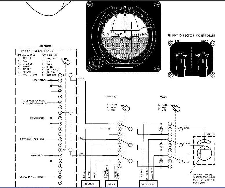
A three axis sphere with 360 degrees of freedom in each axis continuously displays attitude information. The sphere is slaved to the inertial platform gimbals and always indicates platform attitude. Three needle type indicators display attitude and/or attitude! rate information as selected by the pilot. Information displayed on the needles is provided by the computer, platform, radar, and rate gyros. A scale selector is included in the FDI to allow the selection of HI or LO scale indications on the needles. The FDC is used to select the source and type of display on the needles. The ADG image includes a simplified schematic of the FIE switching and indicates the source and type of signal available. Since the computer is capable of producing different types of signals, the computer mode selector is included in the schematic. The FDC reference selector determines the source of display information. The FDC mode selector determines the type of signal displayed.
The Manual Data Insertion Unit (MDIU) consists of a ten digit keyboard and a seven digit register. The MDIU allows the pilot to communicate directly with the on-board computer. Provision is made to enter, cancel or read out information. The keyboard is used to address a specific location in the computer and set up coded messages for insertion. The first two keys that are pressed address the computer memory word location and the next flve set up a coded message. Keys are pressed in a most significant bit first order. Negative values are inserted by making the first number of the message a 9. The 9 then represents a minus sign and not a number. The seven digit register is used to monitor addresses and messages entered into or read out of the computer. Push button switches are included on the register panel to READ, CUT, CLEAR, and the messages. The switch does not clear the computer, it clears only the register. Information can also be inserted in the computer by the ground tracking 6 stations which have Digital Command System capabilities.
Incremental Velocity Indicator
The Incremental Velocity Indicator (IVI) provides a display of computed
velocity
increments required for, or resulting for a specific maneuver. The 1%'I
is controlled
through the on-board computer. Displays are utilized for orbit
insertion, orbit correction, rendezvous maneuvers and retrograde.
Velocity increments are
provided along each of the spacecraft translational axis. Controls are
included
to manually insert plus or minus velocity increments into the IVI. The
IVI also
provides a display of tape position words and module words from the
auxiliary
tape memory.
Computer controls are located on the computer controls and indicators
panel on
the instrument panel - center console (lower assy).
Computer controls consist of: a COMPUTR mode selector, a START switch, a
COMP
light, a MALF light, a RESET switch, and an 0N-OFF switch. The COMPUTER
mode
selector is a seven position rotary switch which selects the type of
calculations
to be performed. Modes of operation correspond to the mission phase in
which
they are utilized. The CO light indicates when the computer is running
through its program and provides a means of checking computer
sequencing. The START switch is utilized for manual initiation of
certain computations.
Note: The START switch must be operated in conjunction with the COMPUTER mode selector and the COMP light.
The HALF light indicates when a malfunction has occurred and the RESET switch resets the computer malfunction indicator. The RESET Switch is only capable of resetting the computer for momentary malfunctions. An ON-OFF switch controls power to the computer and the auxiliary computer power unit.
The IMU controls and indicators consist of; a PLATFORM mode selector, an
ACC light, an ATT light, a RESET switch, and an AC POWER selector. The
PLATF0RM mode selector is a seven position rotary switch which, in
conjunction with the AC POWER selector turns the platform on and off as
well as controls the mode of operation. Two cage modes, two align modes,
one free mode, and an orbit
rate mode of operation are selectable. The align models are SEF and REF.
The ACC light indicates when a malfunction has occurred in the
accelerometer portion of the IMU. The ATT light indicates when a
malfunction has occurred in the attitude portion of the lMU. The RESET
switch will turn off the lights indicating that the IMU has returned to
normal operation. The RESET switch works for momentary functions
of either type. Inability to reset the lights indicates a permanent
malfunction. The AC POWER selector allows the pilot to turn the IGS
inverter on without operating the platform or electronics circuits.
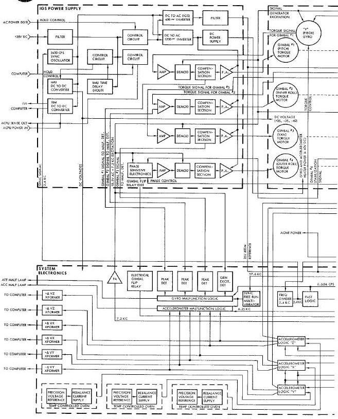
The Inertial Measurement Unit (IMU) is the inertial attitude and acceleration reference for the Gemini Spacecraft. The IMU consists of three separate packages the inertial platform, platform electronics, and IGS power supply. All three packages conform to spacecraft contours for mounting convenience and have a total weight of 130 pounds. A functional block diagram (Figure-Below) indicates functions and signal routing throughout all three packages. In addition to attitude and acceleration reference, the IMU provides ac and dc power for use in other units of guidance and control. The platform and electronics packages are mounted on cold plates to prevent overheating.
Note: References to x, y, and z
attitude and translational axes pertain to inertial guidance only and
should not be confused
with structural coordinate axes.
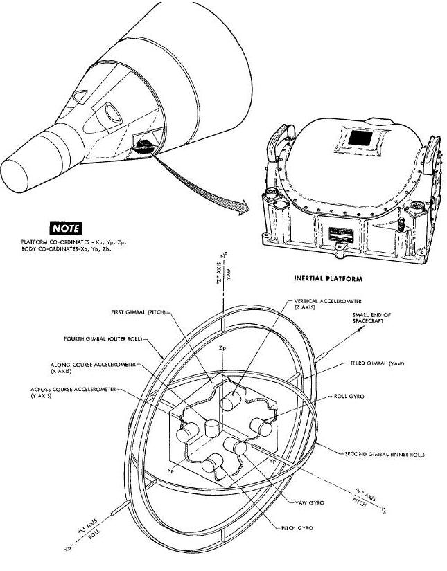
The inertial platform is a four gimbal assembly containing three miniature integrating gyros and three pendulous accelerometers. Gimbals allow the gyro mounting frame (pitch block) to remain in a fixed attitude while the housing moves freely about them. Major components of the platform are: a housing, gimbal structure, torque motors, gimbal angle synchros, resolvers, gyros and accelerometers.
Internal Platform Gimbal Structure
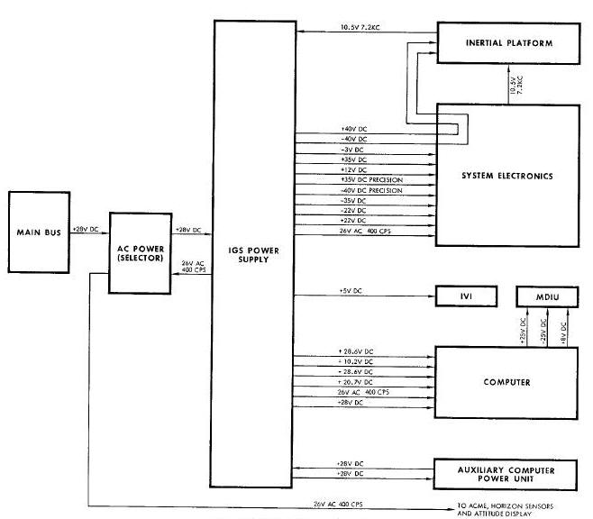
The IGS power supply (Figure
Above) contains
gimbal control electronics and the static power supply unit. Gimbal
control electronics in the torque motors in the platform. Separate
control circuits are provided for leach gimbal. The static power supply
provides the electrical power for the IMU, OBCI ACPU, MDIU, IVI, ACME
and horizon sensors. Figure below indicates the types of power available
and the units to which they are supplied.
Attitude measurements are made from inertial platform gimbals and reflect the difference between spacecraft and gimbal attitudes, platform gimbals are maintained in essentialy a fixed inertial attitude by gimbal control electronics. As the spacecraft moves about the attitude axes, friction transfers some of the movement to platform gimbals. Three miniature gyros are used to sense minute gimbal attitude changes. When gyros sense a change in attitude, they produce a signal proportional to the attitude error. Gyro outputs are then used by gimbal control circuits to drive gimbals to their original inertial attitude. Gimbal positions relative to the spacecraft are measured by synchros and resolvers. Synchro outputs are provided for attitude display, automatic attitude control, and gyro alignment. Two types of resolvers, phase shift and coordinate transformation, are used. Phase shift resolvers provide gimbal angle information to the computer. Coordinate transformation resolvers provide attitude signal resolution for gimbal control purposes.
Seven modes of operation are selectable by the astronaut. The modes, in order of switch position are: OFF, CAGE, SEF, ORB RATE, BEF, CAGE, and FREE. The CAGE position is used for IMU warm-up and to align the platform gimbals with spacecraft body axes. Platform gimbals are caged prior to fine alignment with the horizon sensors. In the CAGE mode, gimbals are torqued by synchro outputs until a null is obtained on the synchro. When synchro outputs reach null, torqueing stops and the gimbals are aligned with spacecraft axes. SEF (Small End Forward) mode is used to align the platform with the horizon sensors when the spacecraft is flying small end forward. Horizon sensor pitch and roll outputs are compared with synchro outputs and the difference used to torque gimbals. When synchro and horizon sensor outputs are balanced the gimbals are aligned to earth local vertical. A gyro compass loop aligns the yaw gimbal with the orbit plane.
NOTE: If horizon sensors lose track during either SEF or BEF alignment modes, the platform is automatically switched to ORB RATE mode.
ORB RATE (orbit rate) mode is used to maintain attitude reference during spacecraft maneuvers. ORB RATE mode is initially free except for the pitch gyro. The pitch gyro is torqued at approximately four degrees per minute to maintain a horizontal attitude with respect to the earth. If ORB RATE mode is used for long periods of time, drift can cause excessive errors in the platform. BEF (Blunt End Forward) mode is the same as SEF except that relays reverse the phase of horizon sensor inputs. The second CAGE mode allows the platform to be caged in blunt end forward without switching back through other modes. mode is used during launch and re-entry phases. FREE mode is completely inertial and the only torqueing employed is for drift compensation.
Note: FREE mode is selected automatically by the Sequential System at retrofire.
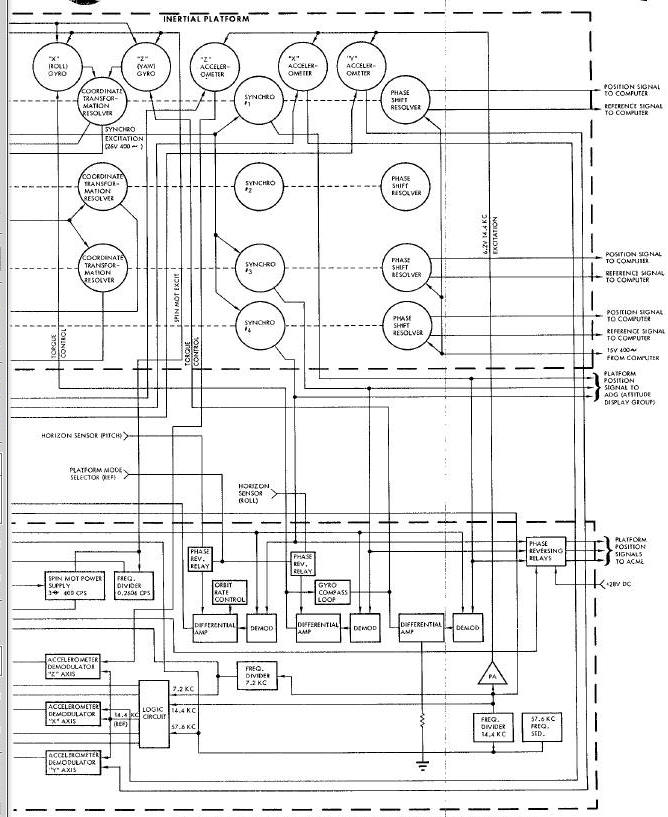
Four separate servo loops provide gimbal attitude control.
Figure
Below illustrates the signal flow through all four loops. Gyro signal
generator outputs are used either directly or through resolvers as the
reference for gimbal control. Both pbsse and amplitude of signal
generator outputs are functions of gimbal attitude. Gimbal number one
(pitch) is controlled directly by the pitch gyro
output. Error signals produced by the pitch gyro are amplified,
demodulated, and compensated, then used to drive the pitch gimbal torque
motor. The first amplifier raises the signal to the level suitable for
demodulation. After amplification, the signal is demodulated to remove
the 7.2 KC carrier. A compensation section keeps the signal within the
rate characteristics necessary for loop
stability. When the signal is properly conditioned by the compensation
section, it goes to a power amplifier. The power amplifier supplies the
current required to drive the gimbal torque motor. The torque motor then
drives the gimbal maintaining gyro Outputs at or very near null.
Roll and yaw servo loops utilize resolvers to correlate gimbal angles
with gyro outputs. Inner roll and yaw gimbals are controlled by a
coordinate transformation resolver mounted on the pitch gimbal. When the
spacecraft is at any pitch attitude other than 0 or 180 degrees, some
roll motion is sensed by the yaw gyro and some yaw motion is
sensed by the roll gyro. The amount of roll motion sensed by the yaw
gyro is proportional to the pitch gimbal angle. The resolver mounted on
the pitch gimbal angle. Resolver
output is then conditioned in the same manner as in the pitch servo loop
to drive inner roll and yaw gimbals.
The outer roll gimbal is servo driven from the inner roll gimbal
resolver. A coordinate transformation resolver mounted on the inner roll
gimbal, monitors the Angle between inner roll and yaw gimbals. If the
angle is anything other than 90 degrees an error signal is produced by
the resolver. The error signal is conditioned in the same manner as in
the pitch servo loop to drive the outer roll
gimbal. One additional circuit (phase sensitive electronics) is included
in the outer roll servo loop. The outer roll gimbal torque motor is
mounted on the platform housing and moves about the stable element with
the spacecraft. As the spacecraft moves through 90 degrees in yaw, the
direction that the outer roll gimbal torque motor must rotate to
compensate for spacecraft roll, reverses.
Phase sensitive electronics and a resolver provide the phase reversal
necessary for control. The resolver is used to measure rotation of the
yaw gimbal about the yaw axis. As the gimbal rotates through 90 degrees
in yaw, the resolver output changes phase. Resolver output is compared
to a reference phase by the phase sensitive electronics. When the
resolver output changes phase, the torque
motor drive signal is reversed.
The IMU is the inertial reference for hack-up ascent guidance and must therefore be aligned for that purpose. The platform is aligned to local vertical and the launch azimuth. Platform X and Y accelerometers are the reference for local vertical alignment. When the platform is aligned to the local vertical, X and Y accelerometers are level and cannot sense any acceleration due to gravity. If any acceleration is sensed, the platform is not properly aligned and must be torqued until no error signal exists. The accelerometer output is used by AGE equipment to generate torque signals for the gyros. When the gyro is torqued it produces an error signal which is used to align the gimbal. The outer roll gimbal synchro output is compared with a signal representing the launch azimuth by AGE equipment. The error signal is conditioned by AGE equipment and applied to the yaw gyro torque generator. The yaw gyro signal generator then produces a signal proportional to the input torque. Gyro output is coordinated by a resolver mounted on the pitch gimbal. Since the spacecraft is in a 90 degree pitch up attitude essentially all of the yaw gyro output is transferred to roll gimbal control electronics. The electronics drive the roll gimbals until no error exists between synchro output and the AGE reference signal. When no error signal exists, the platform is aligned to the launch azimuth.
Alignment of the platform in orbit is accomplished by referencing it to the horizon sensors. Placing the platform mode selector on SEF or BEF position will reference it to the horizon sensors. Pitch and roll horizon sensor outputs are compared with platform pitch and outer roll synchro outputs. Differential amplifiers produce torque control signals proportional to the difference between sensor and synchro outputs. Torque control signals are used to drive pitch and roll gyro torque generators. Gyro signal generator outputs are then used by gimbal control electronics to drive platform gimbals. When synchro and horizon sensor outputs balance, the pitch and roll gimbals are aligned to the local vertical. The yaw gimbal is aligned to the orbit plane through a gyro compass loop. If yaw errors exist, the roll gyro will sense a component of orbit rate. The roll gyro output is used through a gyro compass loop to torque the yaw gyro. Yaw gyro output is then used by gimbal control electronics to drive the yaw gimbal. When the roll gyro no longer senses a component of orbit rate, the yaw gimbal is aligned to the orbit plane. All three gimbals are now aligned and will remain aligned as long as SEF or BEF modes are used. The pitch gyro will be continuously torqued (at the orbit rate) to maintain a horizontal attitude.
Note: If horizon sensors lose track while the platform is in SEF or BEF modes, the platform is automatically switched to ORB RATE mode.
The orbit rate circuit is used to maintain alignment to the local
vertical during orbit maneuvers. Local vertical cannot be provided by
horizon sensors during maneuvers because they will lose track. To
maintain a horizontal attitude with no external reference, the pitch
gyro is torqued at approximately four degrees per minute. The torque
represents the spacecraft orbit rate. Torque is obtained by placing a DC
bias on the output of the pitch differential amplifier. The bias drives
the pitch gyro torque at approximately the orbit
rate. Orbit rate bias is adjustable and can be set to match orbits of
various altitudes.
Phase Angle Shift Technique (PAST) is a method of improving gyro
drift repeatability. One of the factors which affects gyro drift is spin
motor rotor unbalance. The effect of unbalance will vary with changes in
the point of lock on with the synchronous motor's rotating field. The
spin motor can lock on to a different point each time it is started.
Drift errors due to rotor unbalance are in the order of 0.5 degrees per
hour. PAST provides a means of reducing drift errors by a factor of ten.
To cancel drift errors, PAST shifts the phase of spin motor excitation
30 degrees at regular intervals. Shifting the phase causes the rotor to
lock on a different point each time the phase is shifted. Drifts now
tend to cancel and become predictable. (When drift is predictable it can
be compensated for. ) All three gyro torque control loops contain drift
compensation circuits. The drift compensation circuits apply a dc bias
to each
gyro torque generator. Drift compensation torques the gyro in the
opposite direction as predictable drift, maintaining a stable attitude.
Attitude Malfunction Detection
An attitude malfunction detection circuit performs self checks of
gyro signal generator excitation, gimbal control signals, logic
timing signals, and critical voltages. Gyro signal generator excitation
is checked for presence and proper amplitude. Gimbal control signals are
checked for the length of time signals are present. The logic timing
signal (28.8kc) is checked for presence. Critical voltages (+22vdc,
-3vdc, +12vdc) are checked for presence. If a malfunction is detected,
an ATT light on the control panel is automatically illuminated.
If momentary malfunctions occur, the ATT indicator cam be restored to
normal operation by pressing the RESET button.
Note: If the attitude measurement circuits malfunction, the acceleration indications are not reliable. Accelerometer axes will not be properly aligned and indications are along unknown axes.
Acceleration is measured along three mutually perpendicular axes of
the inertial platform. Sensing devices are three miniature pendulous
accelerometers. The accelerometers are mounted in the platform pitch
block and measure acceleration along gyro x, y, and z axes.
Accelerometer signal generators produce signals whose phase is a
function of the direction of acceleration. Signal generator
output is used to control torque rebalance pulses. The torque rebalance
pulses drive accelerometer pendulums toward their null position.
Rebalance pulses are dc current whose polarity is controlled by signal
generator output. The polarity of rebalance pulses indicates the
direction of acceleration and the algebraic sum of the pulses indicates
the amount of acceleration. Rebalance pulses are
supplied to the spacecraft digital computer where they are used for
computations and incremental velocity displays.
Three electrically identical torque rebalance loops are used to
control accelerometer pendulum positions. Normally an analog loop would
be used for this purpose; however, if an analog loop were used, the
output would have to be converted to digital form for use in the
computer. To eliminate the need for an analog to digital converter, a
pulse rebalance loop is used. Short duration 184 milliampere dc current
pulses drive the accelerometer pendulum in one direction until it passes
through null. Pulses are applied at the rate of 3.6kc. When the pendulum
passes through null, signal generator output changes phase. The signal
generator output is demodulated to determine the direction of the
pendulum from null. Demodulator output is used by logic circuits to
control the polarity of rebalance
pulses. If acceleration is being sensed, there will be more pulses of
one polarity than the other. If no acceleration is being sensed, the
number of pulses of each polarity will be equal. In addition to
controlling the polarity of rebalance pulses, logic circuits set up
precision timing of the pulses. Precision frequency inputs from the
timing circuits are the basis for rebalance pulse timing. Precise timing
is essential because the amount of pendulum torque depends on the length
of the current pulse. All pulses are precisely the same duration and
amplitude, therefore total torque is dependent only on the algebraic sum
of the applied pulses. Each time a rebalance pulse is applied to the
accelerometer torque, a pulse is also provided to the computer.
Algebraic su,_tion of the rebalance pulses is performed by the computer.
Pulse Rebalance Current Supply
A pulse rebalance current supply provides the
required current for torque rebalance. Since acceleration measurements
are based on the number of torque pulses it is essential that all pulses
be as near identical as possible. To maintain a stable current, a
negative feedback circuit is employed. The supply output is passed
through a precision resistor and the voltage drop across the resistor
compared to a precision voltage reference. Errors detected by the
comparison are used in the feedback circuit to correct any deviations in
current. To further enhance stability both the current supply and the
precession voltage reference are housed in a temperature controlled oven.
A pendulous accelerometer, unlike a gyro, has an
inherent mass unbalance. The mass unbalance is necessary to obtain the
pendulum action. Due to the unbalance, perfect flotation of the
pendulous gimbal cannot be achieved and consequently pressure is present
on the gimbal bearing. To minimize the stiction effect, caused by
bearing friction, a low amplitude oscillation is imposed on the gymbal.
The oscillation (dither) prevents the gimbal from resting on its bearing
long enough to cause stictlon. To obtain gimbal oscillation, two signals
are required: a 100 cps dither signal and a dc field current. The dc
field current is superimposed on the signal generator excitation and
creates a magnetic field around the gimbal. The I00 cps dither is
applied to a separate (modulator) coil. The dither signal beats against
the dc field, causing the gimbal to oscillate up end down. The dither
motion is not around the output axis and consequently no motion is
sensed by the signal generator.
Accelerometer Malfunction Detection
An acceleration malfunction detection circuit
performs self checks of incremental velocity pulses and critical
voltage. Incremental velocity pulses from each of the three axes are
checked for presence. If pulses are absent longer than 0.35 seconds, it
indicates that a flip flop did not reset between set pulses. The
critical voltage (+12 vdc) is checked for presence. If a malfunction is
detected,
an ACC light on the control panel is automatically illuminated. If
momentary malfunctions occur, the accelerometer malfunction circuit can
be restored to normal operation by pressing the RESET button.
Note: Malfunction of the accelerometer circuits does not affect attitude measurements.
The Auxiliary Computer Power Unit (ACPU) is used
in conjunction with the IGS power supply to maintain the correct dc
voltages at the computer. The computer cannot function properly On low
voltage either as a transient or a depression. Abnormal voltages can
cause permanent changes in the computer memory. Three types of circuits
are provided in the ACPU to prevent a low voltage condition
at the computer. The first circuit is a transient sense and auxiliary
power control circuit. The second circuit is a low voltage Sense and
power control circuit and the third is auxiliary power. The ACPU is
turned on and off with the COMPUTER ON-OFF switch.
The transient sense circuit is designed to sense and correct transient low voltage conditions. A series type transistor voltage regulator holds auxiliary power off the llne as low as IGS power supply computer voltage regulator voltage is normal. If regulator voltage momentarily drops below a minimum of 17.5 volts, the transient sense circuit detects the drop and turns on the series regulator. The regulator then places auxiliary power on the line, and maintains voltage at the desired level.
A low voltage sense circuit prevents the computer from operating on low voltage. When the computer is turned on, the low voltage sense circuit insures that spacecraft bus voltage is above 21 volts before allowing power to be applied to the computer. If the computer is already on when a low voltage condition occurs, the transient sense circuit will maintain normal voltage for 100 milliseconds. If spacecraft bus voltage is not back to normal after 2OO milliseconds the low voltage sense circuit initiates a controlled shutdown of the computer. Computer power is controlled through contacts of a relay in the low voltage sense circuit. When the low voltage sense circuit detects a voltage depression it deenergizes the relay. Contacts of the relay initiate a computer shutdown in a manner identical with the computer power switch. When the low voltage sense circuit turns off the computer it also breaks power to all ACPU circuits except low voltage sense. If power were not broken to the transient sense circuit it would attempt to maintain normal voltage at the c_puter. In attempting to maintain normal voltage the auxiliary power capability would be exceeded.
Auxiliary power consists of a battery and a trickle charger. A O.5 ampere-hour nickel cadmium battery is used to supply computer power during spacecraft bus low voltage transients. The battery will supply up to 9.8 amperes for periods of 100 milliseconds or less. A trickle charger is provided to maintain a full charge on the battery. The charger consists of a transistor oscillator, transformer, and rectifier. The oscillator changes static power supply dc voltage to ac. The ae voltage is then stepped up with a transformer and changed back to dc by a full wave diode rectifier. Rectifier output is then applied, through a current limiting resistor, to the battery. The resistor limits charging current to 25 milliamperes. Provision is included to charge the battery from an external source if desired.
The Digital Computer, hereinafter referred to as the computer, is a binary, fixed point, stored-program, general-purpose computer, used to perform on-board computations. The computer is 18.90 inches high, 14.50 inches wide, and 12.75 inches deep. It weighs 58.98 pounds. External views of the computer are shown in below.
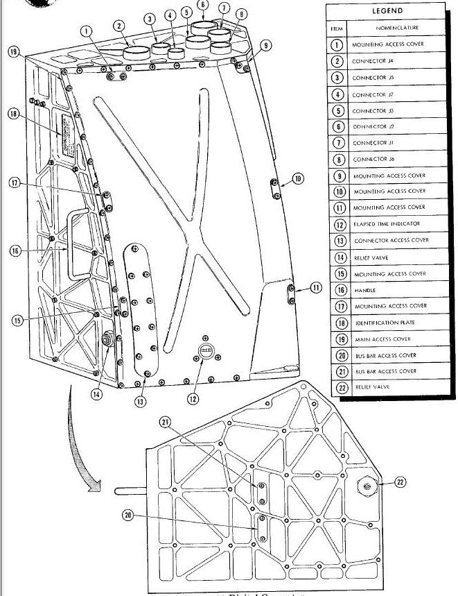
The major external characteristics are summarized in the accompanying legend.
Using inputs from other spacecraft systems, along with a stored program, the computer performs the computations required during the pre-launch insertion, catch-up, rendezvous, and re-entry phases of the mission. In addition, the comuputer provides back-up guidance for the launch vehicle during ascent.
The computer is interfaced with the Inertial Platform System Electronics, Inertial Guidance System Power Supply, Auxiliary Computer Power Unit, Manual Data Insertion Unit, Time Reference System, Digital Command System, Attitude Display, Attitude Control and Maneuver Electronics, Titan Autopilot, Auxiliary Tape Memory (spacecraft 8 through 12), Pilots' Control and Display Panel, Incremental Velocity Indicator, Instrumentation System, and Aerospace Ground Equipment. In connection with these interfaces, the computer inputs and outputs include the following:
Inputs
-
40 discrete
-
3 incremental velocity
-
2 high-speed data (500 kc)
-
1 low-speed data (3.57 kc)
-
1 low-speed data (182 cps)
-
1 input and read-back (99 words)
-
6 dc power (5 regulated, i unregulated)
-
1 ac power (regulated)
Outputs
-
30 discrete
-
3 steering command
-
3 incremental velocity
-
1 decimal display (7 digits)
-
1 telemetry (21 digital data words)
-
1 low-speed data (3-57 kc)
-
1 low-speed data (182 cps)
-
3 dc power (regulated)
-
1 ac power (regulated, filtered)
The major operational characteristics of the computer are as follows:
Type:
Binary, fixed-point, stored-program, general-purpose
Memory:
-
Random-access, nondestructive-readout
-
Flexible division between instruction and data storage
-
4096 addresses, 39 bits per address
-
13 bits per instruction word
-
26 bits per data word
Arithmetic Times:
-
Instruction cycle - 140 usec
-
Divide requires 6 cycles
-
Multiply requires 3 cycles
-
All other instruction require 1 cycle each
-
Other instructions can be progra=med concurrently with multiply and divide
Clock Rates:
-
Arithmetic bit rate - 500 kc
-
Memory cycle rate - 250 kc
The computer itself contains no controls and indicators with the exception of the elapsed time indicator. However, the computer can be controlled by means of four switches located on the Pilots' Control and Display Panel: a two-position ON-OFF switch, a seven-position mode switch, a push-button START Computation switch, and a push-button RESET switch.
The computer receives the ac and dc power required for its operation from the Inertial Guidance System (IGS) Power Supply. The regulated dc power supplied to the computer is buffered in the IGS Power Supply in a manner that eliminates any loss in regulation due to transients that occur in the spacecraft prime power source. Actual power interruptions and depressions arel buffered by the IGS Power Supply and the Auxiliary Computer Power Unit. The power inputs received from the IGS Power Supply are as follows:
-
26 vac and return
-
+28 vdc filtered and return
-
+27.2vdc and return
-
-27.2 vdc and return
-
+20 vdc and return
-
+9.S vdc return
The application of all power is controlled by the 0N-OFF switch on the Pilots' Control and Display Panel. When the switch is turned on, the computer elapsed time indicator starts operating and a power control signal is supplied to the IGS Power Supply by the computer. This signal causes power to be transferred to the computer. When the switch is turned off, the computer elapsed time indicator stops operating and the power control signal is terminated to remove power from the computer.
Within the computer, the 26 vac power is used by magnetic modulators to convert dc analog signals to ac analog signals. This power is also used by a harmonic filter to develop a 16 vac, 400 cps filtered gimbal angle resolver excitation signal. The +28 vdc power is used by computer power sequencing circuits. The +27.2 vdc, -27.2 vdc, +20 vdc, and +9-3 vdc power is used by power regulators to develop +25 vdc, - 25 vdc, and +8 vdc regulated power. This regulated power is used by logic circuits throughout the computer, and is supplied to some of the other spacecraft systems.
The basic computer timing is derived from an 8 mc oscillator. The 8 mc signal is counted down to generate four chock pulses (called W, X, Y, and Z)
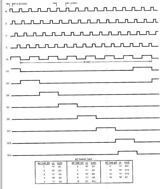
These clock pulses are the basic timing pulses from which all other
timing is generated. The width of each chock pulse is O.375 usec and the
pulse repetition frequency is 500 kc. The bit time is 2 usec, and a new
bit time is considered as starting each time the W clock pulse starts.
Eight gate signals (GI, G3, GS, GT, G9, G11, G13, and G14) are
generated, each lasting two bit times. The first
and second bit times of a particular gate are discriminated by use of a
control signal (called LA) which is on for odd bit times and off for
even bit times. Fourteen bit times make up one phase time, resulting in
a phase time length of 28 usec.
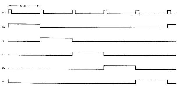
Five phases (PA through PE) are required to complete a computer instruction cycle, resulting in an instruction cycle length of 140 usec. Special phase timing, consisting of four phases (PH1 through PH4) , is generated for use by the input processor and the output processor.
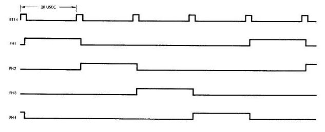
This timing is independent of computer phase timing but is synchronized with computer bit timing.
The computer memory is a random-access,
coincident-current, ferrite array with
nondestructive readout. The basic storage element is! a two-hole ferrite
core.
The nondestructive read property makes it possible to read or write
serially or in
series-parallel, thereby allowing operation with a serial arithmetic unit
without
a separate buffer register. The memory array can store 4096 words, or
159,744
bits. A1 memory words of 39 bits are divided into three syllables of 13
bits
each. Data words (25 bits and a sign) are normally stored in the first
two
syllables, and instruction words (13 bits) are intermixed in all three
syllables.
Once the spacecraft has been removed from the hangar area, it is not
possible to
modify the third syllable of any memory word. Modification of data
stored in
syllables 0 and i can be accomplished at the launch site through
interface with
the Manual Data Insertion Unit or the Digital Command System. It can also
be
accomplished in flight, on spacecraft 8 through 12, using the Auxiliary
Tape
Memory(ATM).
As shown below, the memory is a 64 x 64 x 39 bit array of nondestructive readout elements.
Computer Memory Functional Organization
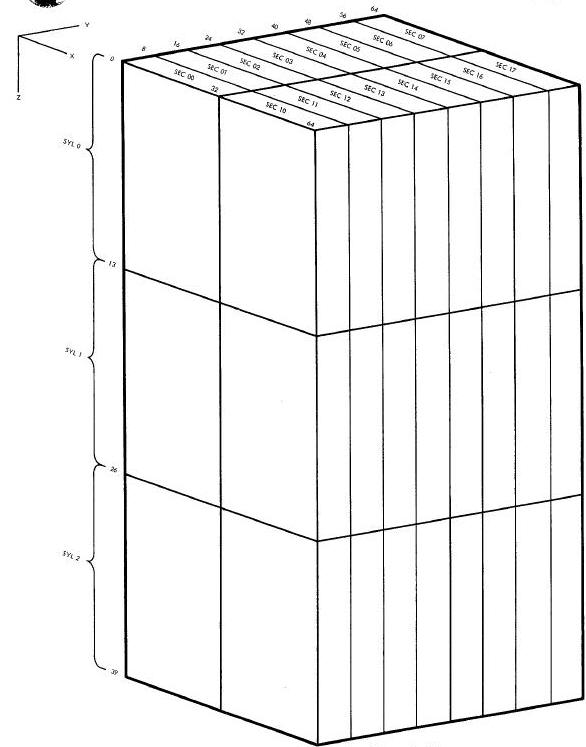
Physically, it consists of a stack of 39 planes (stacked in the Z dimension), with each plane consisting of a 64 x 64 array of cores. The memory is logically subdivided into smaller parts to increase the program storage efficiency. The Z dimension is divided into three syllables (SYL O through SYL 2), with each syllable consisting of 13 bits. The X-Y plane is divided into 16 sectors (SEC O0 through SEC 07, and SEC lO through SEC 17), with sector 17 being defined as the residual sector.
A memory word is defined as the 39 bits along
the Z dimension and is located at one of the 4096 possible X-Y grid
positions. An instruction word or command requires 13 bits, and is coded
in either syllable O, l, or 2 Of a memory word. A data word requires 26
bits, and is always coded in syllables O and I of a memory word.
Information requires 26 bits, and is always coded in syllables O and I
of a memory word. Information stored in syllable 2 can be read as a
short data word by using a special mode of operation primarily used to
check the contents Of the memory.
Note: The operation codes mentioned in the subsequent paragraphs are described in the Instruction and Data Words paragraph.
The instructions which can be executed by the computer are as follows:
| Operation Code | Instruction | ||||||||||||||||||||||||
| 0010 | PRO (process input or output). The input or output specified by the operand address is read into, or loaded from, the accumulator. An output command clears the accumulator to zero if address bit A9 is a 1. The accumulator contents are retained if A9 is a O. (Refer to Table 8-1 for a ]ist of the PRO instructions.) |
||||||||||||||||||||||||
| O011 | RSU (reverse subtract). The contents of the accumulator are subtracted from the contents of the specified memory location. The result is retained in the accmnulator. |
||||||||||||||||||||||||
| 0100 | ADD. The contents of the memory location specified by the operand address are added to the contents of the accumulator. The result is retained in the accumulator. |
||||||||||||||||||||||||
| 0101 | SUB (subtract). The contents of the memory location specified by the operand address are subtracted from the contents of the accumulator. The result is retained in the accumulator. |
||||||||||||||||||||||||
| 0110 | CLA (clear and add). The contents of the memory location specified by the operand address are transferred to the accumulator. |
||||||||||||||||||||||||
| 0111 | AND. The contents of the memory location specified by the operand address are logically ANDed bit-by- bit, with the contents of the accumulator. The result is retained in the accumulator. |
||||||||||||||||||||||||
| 1000 | MPY (multiply). The contents of the memory location specified by the operand address are multiplied by the contents of the accumulator. The 24 high-order bits of the multiplier and miltiplicand are multiplied together to form a 26-bit product which is available in the product delay line during the second word time following the MPY. |
||||||||||||||||||||||||
| 1O01 | TRA (transfer). The operand address bits (AI through AP) are transferred to the instruction address counter to form a new instruction address. The syllable and sector remain unchanged. |
||||||||||||||||||||||||
| 1010 | SHF (shift). The contents of the accumulator are shifted left or right, one or two places, as specified by the operand address, according to the following table: |
||||||||||||||||||||||||
|
|||||||||||||||||||||||||
| 1011 | TMI (transfer on minus accumulator sign). If the sign is positive (0), the next instruction in sequence is chosen (no branch). If the sign is negative (i), the nine bits of operand address become the next instruction address (perform branch). The syllable and sector remain unchanged. |
||||||||||||||||||||||||
| 1100 | STO (store). The contents of the accumulator are stored in the memory location specified by the operand address. The contents of the accumulator are also retained for later use. |
||||||||||||||||||||||||
| 1101 | SPQ (store product or quotient). The product is available on the second word time following an MPY. The quotient is available on the fifth word time following a DIV. The product or quotient is stored in the memory location specified by the operand address. |
||||||||||||||||||||||||
| 1110 | CLD (clear and add discrete). The state of the discrete input selected by the operand address is read into all accumulator bit positions. (Refer to Table 8-2 for a list of the CLD instructions. ) |
||||||||||||||||||||||||
| 1111 | TNZ (transfer on non-zero). If the contents of the accumulator are zero, the next instruction in sequence is chosen (no branch); if the contents are non-zero, the nine bits of operand address become the next instruction address (perform branch). The syllable and sector remnln unchanged. |
||||||||||||||||||||||||
NOTE: The instructions mentioned in the subsequent paragraphs (e.g., HOP, TRA, TMI, and TNZ) are described more completely in the
Instruction Information Flow paragraph.
Instruction Sequencing
The instruction address is derived from an instruction counter and its associated address register. To address an instruction, the syllable, sector, and word position within the sector (one of 256 positions) must be defined. The syllable and sector are defined by the contents of the syllable register (two-bit code, three combinations) and sector register (four-bit code, 16 combinations). These registers can be changed only by a HGP instruction. The word position within the sector is defined by the instruction address counter. The instruction address count is stored serially in a delay line; and normally each time it is used to address a new instruction, a one is added to it so that the instruction locations within a sector can be sequentially scanned. The number stored in the counter can be changed by either a TRA, TMI, or TNZ instruction, With the operand address specifying the new number. A HOP instruction can also change the count, with the new instruction location coming from a data word.
CLD Instruction Programing
| Operand Address | Signal | |
| X (Bits AI-AB) | Y (Bits A_-A6) | |
| 0 | 0 | Radar read |
| 0 | 1 | Computer Mode2 |
| 0 | 2 | Spare |
| 0 | 3 | Processor timing phase 1 |
| 0 | 4 | Spare |
| 1 | 0 | Data ready |
| 1 | 1 | Computer mode 1 |
| 1 | 2 | Start computation |
| 1 | 3 | X zero indication |
| 1 | 4 | ATM clock |
| 2 | 0 | Enter |
| 2 | 1 | Instrumentation System sync |
| 2 | 2 | Velocity error count not zero |
| 2 | 3 | Aerospace Ground Equipment request |
| 2 | 4 | Spare |
| 3 | 0 | Readout |
| 3 | 1 | Computer mode 3 |
| 3 | 2 | Spare |
| 3 | 3 | ATM on |
| 3 | 4 | ATM data channel 2 |
| 4 | 0 | Clear |
| 4 | 1 | ATM mode control 1 |
| 4 | 2 | Simulation mode command |
| 4 | 3 | ATM end of tape |
| 4 | 4 | ATM data channel 3 |
| 5 | 0 | Time to start re-entry calculations |
| 5 | 1 | ATM mode control 2 |
| 5 | 2 | Y zero indication |
| 5 | 3 | ATM data |
| 5 | 4 | Spare |
| 6 | 0 | Digital Command System ready |
| 6 | 1 | Fade-in discrete |
| 6 | 2 | Z zero indication |
| 6 | 3 | Umbilical disconnect |
| 6 | 4 | Spare |
| 7 | 0 | Instrumentation System request |
| 7 | 1 | Abort transfer |
| 7 | 2 | Aerospace Ground Equipmnent input data |
| 7 | 3 | Spare |
| 7 | 4 | Spare |
Instruction and Data Words
The instruction word consists of 13 bits and can be coded in any syllable of any memory word. The word is coded as follows :
| Bit Position | 1 | 2 | 3 | 4 | 5 | 6 | 7 | 8 | 9 | 10 | 11 | 12 | 13 |
| Bit Code | A1 | A2 | A3 | A4 | A5 | A6 | A7 | A8 | A9 | OP1 | OP2 | OP3 | OP4 |
The four operation bits (0P1 through 0P4) define one of 16 instructions, the eight operand address bits (A1 through A8) define a memory word within the sector being presently used, and the residual bit (A9) determines whether or not to read the data residual. If the A9 bit is a 1, the data word addressed is always located in the last sector (sector 17). If the A9 bit is a 0, the data word addressed is read from the sector defined by the contents of the sector register. This feature allows data locations to be available to instructions stored anywhere in the memory.
The data word consists of 25 magnitude bits and a sign bit. Numbers are represented in two's-complement form, with the low-order bits occurring at the beginning of the ward and the sign bit occurring after the highest-order bit. The binary point is placed between bit positions 25 and 26. The bit magnitude number also denotes the binary weight of the position. For example, M16 represents 2 to the -16. For the HOP instruction, the next instruction address is coded in a data word that is read from the memory location specified by the operand address of the HOP word. The codings of a numerical data word and a HOP word are as follows :
| Bit Position | 1 | 2 | 3 | 4 | 5 | 6 | 7 | 8 | 9 | 10 | 11 | 12 | 13 |
| Data Word | M25 | M24 | M23 | M22 | M21 | M20 | M19 | M18 | M17 | M16 | M15 | M14 | M13 |
| HOP Word | A1 | A2 | A3 | A4 | A5 | A6 | A7 | A8 | A9 | S1 | S2 | S3 | S4 |
| Bit Position | 14 | 15 | 16 | 17 | 18 | 19 | 20 | 21 | 22 | 23 | 24 | 25 | 26 |
| Data Word | M12 | M11 | M10 | M9 | M8 | M7 | M6 | M5 | M4 | M3 | M2 | M1 | S |
| HOP Word | SYA | SYB | S5 |
For the HOP word, eight address bits (A1 through A8) select the next instruction (one of 256) within the new sector, the residual bit (A9) determines whether or not the next instruction is located in the residual sector, the sector bits (S1 through S4) select the new sector, and the syllable bits (SYA and SYB) select the new syllable according to the following table :
| Sylable | SYA | SYB |
| 0 | 0 | 0 |
| 1 | 0 | 1 |
| 2 | 1 | 0 |
The special syllable bit (S5) determines the mode in which data words are to be read. If the S5 bit is a 0, normal operation of reading data words from syllables 0 and 1 is followed; however, if the S5 bit is a 1, data words are read from syllable 2 only. These data words contain information from syllable 2 in bit positions 1 through 13, but contain all 0's in bit positions 14 through 26. This special mode is followed until a new HOP command places the computer back in the normal mode of reading data words. (While in the special mode, any HOP word addressed always has 0's coded in the SYA, SYB, and S5 positions due to the short data word that is read; therefore, any HOP word coded while in this mode terminates the mode and operation is resumed In syllable 0.). The computer itself does not have the capability to store information in Syllable 2; therefore, ST0 and SPQ commands are not executed while in the special mode. The mode is used only to allow the computer arithmetic circuits to check the entire memory contents to verify the fact that the proper information is in storage.
In a HOP word, the residual bit (A9) overrides the sector bits (S1 through S4). If the A9 hit is a 1, the next instruction is read from the residual sector. If, however, the A9 bit is a 0, the S1 through S4 bits determine the sector from which the next instruction is read.
For convenience, the data and instruction words can be coded in an octal form that is easily converted to the machine binary representation. The order in which the bits are written is reversed to conform to the normal method of placing lower significance
bits to the left so that, while performing arithmetic, the low-order bits are accessed first.) The coding structure Is as follows:
| Instruction Word | OP4 | OP3 | OP2 | OP1 | A9 | A8 | A7 | A6 | A5 | A4 | A3 | A2 | A1 | |
| Data Word | S | M1 | M2 | M3 | M4 | M5 | M6. | ... | .M20 | M21 | M22 | M23 | M24 | M25 |
| *Y Address *X Address | ||||||||||||||
| *Addresses for CLD and PRO instructions | ||||||||||||||
where each group of three bits is expressed as an octal character (from 0 to 7). An instruction word is thus expressed as a five-character octal number. The operation code can take on values from 00 to 17, and the operand address can take on values from 000 to 777. Any operand address larger than 377 addresses the residual sector (sector 17) because the highest-order address bit (A9) is also the residual identification bit. A data word is expressed as a nine-character octal number, taking on values from 000000000 to 777777776. The low-order character can take on only the values of O, 2, 4, and 6.
Arithmetic Elements
The computer has two arithmetic elements: an add-subtract element (accumulator), and a multiply-divide element. Each element operates independently of the other; however, both are serviced by the same program control circuits. Computer operation times can be conveniently defined as a number of cycles, where a cycle time represents the time required to perform an addition (140 usec). All operations except MPY and DIV require one cycle; MPY requires three cycles, and DIV requires six cycles. Each cycle, the program control is capable of servicing one of the arithmetic elements with an instruction. An MPY or a DIV instruction essentially starts an operation in the multiply-divide element, and the program control must obtain the answer at the proper time since the multiply-divide element has no means of completing an operation by itself. When an MPY is commanded, the product is obtainable from the multiply-divide element two cycle times later by an SPQ instruction. When a DIV is commanded, the quotient is obtainable five cycle times later by an SPQ instruction.
It is possible to have one other instruction run concurrently between the MPY and the SPQ during multiply, and four other instructions run concurrently between the DIV and the SPQ during divide. However, an MPY or a DIV is always followed with an SPQ before a new MPY or DIV is given.
Basic Information Flow
Refer to Figure below for the following description of information flow during the five computer phase times. The description is limited to those operations requiring only one cycle time, and thus does not pertain to MPY and DIV.
Basic Information Flow Diagram
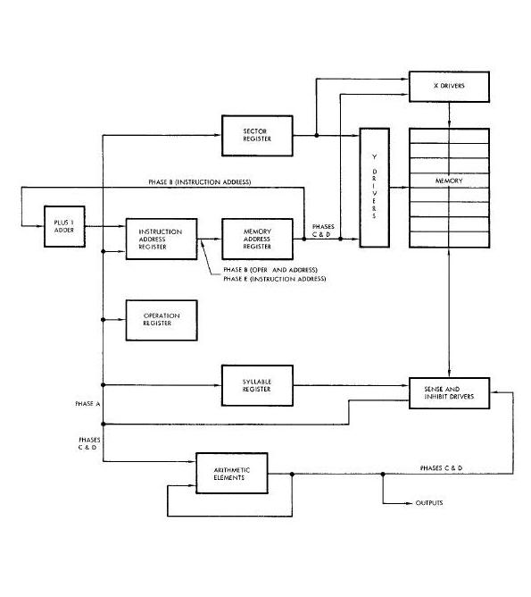
During phase A, the 13-bit instruction word is read from memory and stored in the During phase A, the 13-bit instruction word is read from memory and stored in the instruction address register. The address of the instruction is defined by the During phase A, the 13-bit instruction word is read from memory and stored in the During phnse A, the 13-bit instruction word is read from memory and stored in the During phnse A, the 13-bit instruction word is read from memory and stored in the During phase A, the 13-bit instruction word is read from memory and stored in the During phase A, the 13-bit instruction word is read from memory and stored in the During phase A, the 13-bit instruction word is read from memory and stored in the During phase A, the 13-bit instruction word is read from memory and stored in the During phase A, the 13-bit instruction word is read from memory and stored in the During phase A, the 13-bit instruction word is read from memory and stored in the instruction address register. The address of the instruction is defined by the contents of the memory address register, the sector register, and the syllable register. The four operation code bits (OP1 through 0P4) are stored in the operation register. During phase B, the operand address bits (A1 through A8) are serially transferred from the instruction address register to the memory address register. Simultaneously, the instruction address stored in the memory address register is incremented by plus one and stored in the instruction address register. The operation specified by the operation code bits is performed during phases C and D. During phase E, the next instruction address Stored in the instruction address register is transferred to the memory address register.
Four of the one-cycle operations do not strictly adhere to the above information flow. These operations are HOP, TRA, TMI, and TNZ. For the HOP instruction, data read from memory during phases C and D is transferred directly to the instruction address register, the sector register, and the syllable register. For the TRA, TMI, and TNZ operations, the transfer of the next instruction address from the
instruction address register during phase E is inhibited to allow the operand address to become the next instruction address.
Instruction Information Flow
Flow Diagram: The instruction information flow diagram (Figure Below) should be used along with the following descriptions.
Instruction Information Flow Diagram
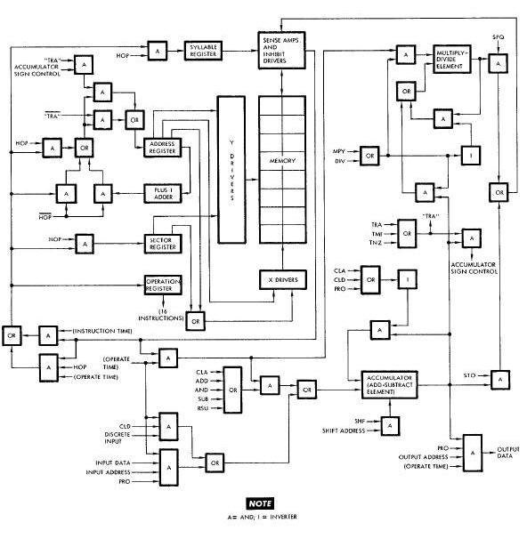
CLA Operation
During phases C and D, the data that was contained in the accumulator during phases A and B is destroyed. Simultaneously, new data from the selected memory location is transferred through the sense amplifiers and into the accumulator. During phases E and A, the new data is recalculated so as to be available in the accumulator during phases A and B.
ADD Operation
During phases C and D, new data from the selected memory location is transferred through the sense amplifiers and into the accumulator. Here, the new data is added to the data that was contained in the acctamulator during phases A and B. During phases E and A, the sum data is recalculated so as to be available in the accumulator during phases A and B.
SUB Operation
During phases C and D, new data from the selected memory location is transferred through the sense amplifiers and into the accumulator. Here, the new data is subtracted from the data that was contained in the accumulator during phases A and B. During phases E and A, the difference data is recirculated so as to be available in the accumulator during phases A and B.
RSU Operation
During phases C and D, new data from the selected memory location is transferred through the sense amplifiers and into the accumulator. Here, the data that was contained in the accumulator during phases A and B is subtracted from the new data. During phases E and A, the difference data is recalculated so as to be available in the accumulator during phases A and B.
AND Operation
During phases C and D, new data from the selected memory location is transferred through the sense amplifiers and into the accumulator. Here, the new data is ANDed with the data that was contained in the accumulator during phases A and B. During phases E and A, the ANDed data is reelrculatedlso as to be available in the accumulator during phases A and B.
SHF Operation
During phases C and D, the data that was contained in the accumulator during phases A and B is shifted left or right, one or two places, as specified by the operand address. During phases E and A, the shifted data is recalculated so as to be available in the accumulator during phases A and B.
STO Operation
During phases C and D, the data that was contained in the accumulator during phases A and B is transferred through the inhibit drivers and stored in the memory
H0P Operation
During phases C and D, new data from the selected memory location is transferred through the sense amplifiers and into the address, sector, and syllable registers. Here, the new data is used to select the address, sector, and syllable of the memory location from which the next instruction will be read.
TRA Operation
During phases A and B, the instruction from the selected memory location is transferred through the sense amplifiers and into the address register. Here, the instruction is to select the address of the memory location from which the next instruction will be read. The sector and syllable remain unchanged.
TMI Operation
During phases A and B, the instruction from the selected memory location is transferred through the sense amplifiers and into the address register. Here, if the accumulator sign is negative, the instruction is used to select the address of the memory location from which the next instruction will be read. However, if the accumulator sign is positive, the next instruction address in sequence is selected in the normal manner. The sector and syllable remain unchanged.
TNZ Operation
During phases A and B, the instruction from the selected memory location is transferred through the sense amplifiers and into the address register. Here, if the contents of the accumulator are not zero, the instruction is used to select the address of the memory location from which the next instruction will be read. However, if the contents of the accumulator are zero the next instruction address in sequence is selected in the normal manner. The sector and syllable remain unchanged.
CLD Operation
During phases C and D, the data that was contained in the accumulator during phases A and B is destroyed. Simultaneously, the state of the discrete input selected by the operand address is transferred into all accumulator bit positions. During phases E and A, the new data is reeirculated so as to be available in the accumulator during phases A and B.
PRO Operation (Inputs; when A9=1)
During phases C and D, the data that was contained in the accumulator during phases A and B is destroyed. Simultaneously, the data on the input channel selected by the operand address is transferred into the accumulator. During phases E and A, the new data is recirculated so as to be available in the accumulator during phases A and B.
PRO Operation (Inputs; when A9=O)
During phases C and D, the data on the input channel selected by the operand is transferred into the accumulator. Here, the new data is ORed with the data that was contained in the accumulator during phases A and B. During phases E and A, the ORed data is recirculatad so as to be available in the accumulator during phases A and B.
PRO Operation (Outputs)
During phases C and D, the data that was contained in the accumulator during phases to the output channel A end B is transferred selected by the operand address. If the A9 bit of the operand address is a i, the data that was contained in the accumulator during phases A and B is then destroyed. However, if the A9 bit is a 0, the data is reclrculated so as to be available in the accumulator during phases A and B.
MPY Operation
During phases A and B of the first instruction cycle, the data that is contained in the accumulator is transferred into the multiply-divide element as the multiplier. During phases C and D of the same cycle, new data from the selected memory location is transferred through the sense amplifiers and into the multiply divide element as the multiplicand. During the remainder of the first instruction
cycle and the next two instruction cycles, the multiplicand is multiplied by the multiplier. The product is available in the multiply-divide element during phases C and D of the third instruction cycle.
DIV Operation
During phases A and B of the first instruction cycle, the data that is contained in the accumulator is transferred into the multiply-divide element as the divisor. During phases C and D of the same cycle, new data from the selected memory address is transferred through the sense amplifiers and into the multiply-divide element as the dividend. During the remainder of the first instruction cycle and the next five instruction cycles, the dividend is divided by the divisor. The quotient is available in the multiply-divide element during phases C and D of the sixth instruction cycle.
SPQ Operation
During phases C and D, the product or quotient that is contained in the multiply divide element is transferred through the inhibit drivers and stored in the memory location selected by the operand address.
NOTE; In the subsequent program and interface descriptions, the signals that are programmed by CLD and PRO instructions are
sometimes referred to as DI (Discrete Input) or DO (Discrete Output) signals. The two digits following the DI or DO are the Y and X addresses, respectively, of the instructions.
OPERATIONAL PROGRAM
General
Two different programs are used with the rendezvous configuration of the spacecraft. For spacecraft 6, the sixth operational program is utilized. For spacecraft 8 and up, the seventh operational program is used. The primary difference between the two is that the latter is a modular program and is used in conjunction with the Auxiliary Tape Memory (ATM).
Sixth Operational Program
The sixth operational program consists of six basic routines, called executor, pre-launch, ascent, catch-up, rendezvous, and re-entry. Eech routine is made up of several subroutines. Some of the subroutines are common to all routines while some are unique to a particular routine. Each subroutine consists of a series of program instructions which, when executed, cause specific computer circuits
to operate. The initiation of a particular routine is controlled by the COMPUTER mode switch on the Pilots' Control and Display Panel. Once a routine is initiated, the subroutines within the routine are executed automatically.
Executor Routine
The executor routine selects, and handles the functions common to, all other routines. The program flow for this routine is shown on Figure Below. The individual blocks shown on the figure are explained as follows:
Executor Routine Program Flow Diagram
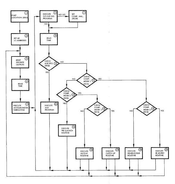
(a) Block 1. When the computer is turned on, the first memory location addressed is address 000, sector 00, syllable O. This memory
location is the first memory address utilized by the executor routine .
(b) Block 2. The operational program utilizes special predetermined memory locations which are designed as Logical Choice (LC) addresses. At certain times, the sign bits at these LC addresses are set minus (1) or plus (0). The sign bits of specific LC addresses are then checked during the execution of the routines and, depending on whether they are plus or minus, special series of program instructions are executed.
(c) Block 3. The following discrete outputs are set plus: start computation, computer running, second stage engine cutoff, autopilot
scale factor, AGE data clock, and Time Reference System gate.
(d) Block 4. The processor real time count is read for utilization by the individual routines.
(e) Block 5. The accelerometer subroutine is executed to verify that the X, Y and Z velocity signals from the accelerometers equal zero.
(f) Block 6. A special go, no-go diagnostic program is executed to determine if the basic computer arithmetic circuits are functioning
properly. If these circuits fail, the NO GO path is followed; if there is no failure, the GO path is followed.
(g) Block 7. Program instruction PR034 is executed. The execution of this instruction causes the computer malfunction circuit to be conditioned.
(h) Block 8. The processor real time count is read and updated for utilization by the individual routines.
(i) Block 9. Program instruction CLD32 is executed to determine the condition of the AGE request discrete input. If the input is a
1, the YES path is followed; if the input is a O, the NO path is followed.
(J) Block 10. Special check-out tests are executed by the AGE. Both the Gemini Launch Vehicle and the computer can be checked out.
(k) Blocks 11 through 14. Program instructions CLD10, CLD11, and CLD13 determine the condition of the discrete inputs from the Computer mode switch. This switch is manually controlled by the pilot and, depending upon which mode is selected, causes a particular routine to be executed until the switcl setting is changed or until the computer is turned off. The combinations of COMPUTER mode switch discrete inputs required to select a particular routtne are as follows.
| Routine | Descrite Inputs | ||
| D110 | D111 | D113 | |
| Pre-Launch | 0 | 0 | 0 |
| Ascent | 1 | 0 | 0 |
| Catch-Up | 1 | 0 | 1 |
| Rondezvous | 0 | 1 | 0 |
| Re-Entry | 0 | 1 | 1 |
(l) Blocks 15 through 19. Depending on the setting of the COMPUTER mode switch, one of these operationaliroutines is selected. The l
individual routines are discussed in Subsequent paragraphs.
Pre-launch Routine
The pre-launch routine provides the instructions required to check out the computer prior to launch and to read in special data for future use. This routine performs sum-checks on all sectors within the computer memory. These checks are performed by adding the contents of all memory addresses within a sector and comparing the sum with a pre-stored constant. If the constant and the sum are not equal, the computer malfunction latch is set by program instruction PR034. If the sum check is successful, special data is stored in predetermined memory addresses by the common subroutines. These subroutines are discussed in later paragraphs.
Ascent Routine
The ascent routine provides the computations required for back-up ascent guidance. After the computer has been placed in the ascent mode, special data is transferred to the computer via the Digital Command System. This data is then continually updated
and used to keep track of the orbit plane and the platform attitude with respect to Earth. Thirty seconds after the special data is first transferred to the computer, the Inertial Guidance System is placed in the inertial mode. The computer continually monitors and stores the platform gimbal angle values during this time. After lift-off, the computer performs a back-up guidance function. If necessary, however, the computer can he used to perform prlmary guidance during ascent.
Catch-up Routine
The catch-up routine provides the computations required to properly position the spacecraft for rendezvousing. During the catch-up mode, gimbal angle values and incremental velocity values are computed. Calculated data is then supplied to the Attitude Display so that the spacecraft can be properly positioned for rendezvousing.
Rendezvous Routine
The rendezvous routine provides the computations required for achieving a rendezvcus. The routine performs essentially the same function as the catch-up routine, with the addition of radar data computations. The radar data is transferred to the conjurer from the rendezvous radar and utilize line computations. These computations are used to achieve a rendezvous between the spacecraft and the target. During the re-entry mode, the retrograde velocity is monitored and retrograde velocity errors are calculated. The distance and heading of the spacecraft with respect to the desired landing site are calculated, and the down range travel to touchdown is predicted. The routine also provides signals to command the spacecraft roll maneuvers during re-entry and provides a display of attitude errors.
NOTE; The following subroutines are common to the previously described routines: gimbal angle, accelerometer, Digital Command System, Instrumentation System, and manual data. Therefore, a description of each of these subroutines follows.
Gimbal Angle Subroutine
The gimbal angle subroutine reads and processes the gimbal angles for the pitch, yaw, and roll axes of the Inertial Platform. During a computer word time, the gimbal angle processor reads in one gimbal angle value and transfers a previously read glmbal angle value to the accumulator. This method enables a faster processing operation than if the angle for each axis were processed, individually.
Approximately 5 ms elapses between the processing of lone gimbal angle value and the processing of the next gimbal angle value. (The gimbal angle value is the binary equivalent of the actual gimbal angle. )
Accelerometer Subroutine
The accelerometer subroutine processes velocity signal inputs from the Inertial Measuring Unit. These signals, which represent velocity for the X, Y, and Z axes of the spacecraft, are generated by accelerometers. Due to the construction and adjustment of the accelerometers, the signals contain inherent bias and alignment errors. The subroutine corrects these errors and stores the corrected velocity values in predetermined computer memory locations. The computer input processor reads the X, Y, and Z velocity signals, and transfers them to the processor delay line. The delay line is then read by the subroutine at periodic intervals which depend on the selected mode or routine.
Digital Command System Subroutine
The Digital Command System subroutine reads and processes data furnished by the Digital Command System (DCS). The DCS furnishes the computer with special 24-bit words consisting of 6 address bits and 18 data bits. The address bits indicate where the data bits are to be stored in the computer memory. The subroutine first determines if data is available from the DCS. If data is available, the subroutine then reads the data into the accumulator. Next, the address and data bits are separated. The data bits are then stored in the computer memory address specified by the address bits. After this data is stored, it is used as constants by other subroutines.
The DCS subroutine also contains instructions which provide extended DCS addresses. (Address 100-117). The recognition of addresses 20 and 21 exercises the proper operational program loops to store the data in the computer. For each DCS extendsd
address insert, it is necessary to make two transmissions and this must be accomplished in the proper order (i.e., DCS address 20 first, 21 next). On the first cycle through the DCS subroutine, address 20 is recognized and the associated data is stored as high order data. On the second cycle, address 21 is recognized and the associated data yields low order data plus the DCS extended
address word. With the DCS extended address, it is possible to insert 26-bit words into the computer.
Instrumentation System Subroutine
The Instrumentation System subroutine assembles special data and transfers it to the Instrumentation System. Every 2.4 seconds, 21 data words are transferred to the Instrumentation System by the subroutine. The transferred data words are the stored results of other subroutines. The types of data words transferred include velocity changes for the X, Y, and Z axes, gimbal angle values for the
pitch, roll, and yaw axes, and radar range. Once every 2.4 seconds, the Instrumentation System sync discrete input occurs. When the input occurs, the data words to be transferred are assembled in a special instrumentation System memory buffer. The buffer consists of 21 predetermined memory addresses. A special memory address is used as a word selection counter tO determine which data words
in the Instrumentation System memory buffer are to be transferred to the Instrumentation System.
Manual Data Subroutine
The manual data subroutine determines when data is transferred from the Manual Data Keyboard (MDK) to the computer and from the computer to the Manual Data Readout (MDR). The subroutine consists of approximately I000 instructions which are used to govern the generation of signals that control circuit operation in the MDK and MDR.
Seventh Operational Program
The seventh operational program consists of six modules. At this time, spacecraft 8 and 9 are scheduled to use modules I, IV and V. Spacecraft i0 is scheduled to use all six modules. Each module contains certain routines and subroutines as discussed below and under Sixth Operational Program.
Module I
Module I represents that portion of the program which is always maintained in the computer memory. It contains the programming required for the pre-launch mode as well as that associated with the executer functions, diagnostic subroutines, computational subroutines and the ATM read programs.
Module II
Module II consists of the ascent computer mode, a simplified catch-up mode (no radar interface) and that portion of the re-entry mode required for ascent/abort re-entry guidance. For ascent/abort re-entry, the computer mode selector remains in ASC.
Module III
Module III consists of the catch-up and rendezvous modes as described under Sixth Operational Program.
Module IV
Module IV contains the touchdown predict and re-entry modes. The touchdown predict mode provides an on-board capability for predicting the half-llft touchdown point on the basis of ground-computed orbital initial condition data and a selected trial retrograde time. The calculated time-to-go to retrograde and the associated retrograde initial conditions may be automatically transferred
to the Time Reference System (TRS) and re-entry program, respectively, for subsequent initialization of the re-entry mode. The re-entry mode is generally the same as that described for the Sixth Operational Program.
Module V
Module V contains the ascent mode of module II, without the ascent/abort capability, and the catch-up and rendezvous modes of module III without the rendezvous self test. The purpose of modnle V is to insure that ATM load failure will not Jeopardize completion of rendezvous mission objectives.
Module VI
Module VI contains the orbit predict, orbit navigation, and orbit determination modes.
The orbit predict mode provides the capability to calculate the velocity and position of the spacecraft or target vehicle (or their relative velocity and position) as much as three orbits into the future or 0ne orbit into the past. This mode also provides the capability to simulate impulsive velocity changes in the spacecraft orbit. This is accomplished by accepting velocity change inputs in the guidance axes while the orbit computation is not in progress.
The orbit navigation mode provides the means to navigate the spacecraft during velocity and position changes by including the accelerometer outputs in the computer equations of motion.
The orbit determination mode provides the capability to improve the on-board navigation accuracy by processing the measurements of star to horizon angle or star to local verticle angle taken aboard the spacecraft.
INTERFACES
Figure below shows the equipment which interfaces with the computer. The diagram also contains references to the individual equipment interface diagrams.
Computer Interface Diagram
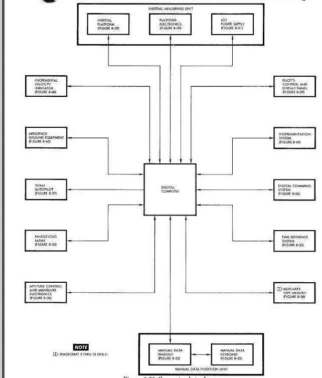
Inertial Platform (Figure Below)
The computer supplies 400 cps excitation to the rotors of three resolvers located on the pitch, roll, and yaw gimbal axes of the inertial Platform. Movement of the rotors of any of these resolvers away from their zero (platform-caged) reference causes the output voltage of the stator winding to be phase-shifted relative to the reference 400 cps voltage inputs to the computer: a reference voltage from the compensator winding (pitch, yaw, and roll references), and a phase-shifted voltage from the stator winding (pitch, yaw, and roll gimbal angles).
Inertial Computer Platform Interface Diagram
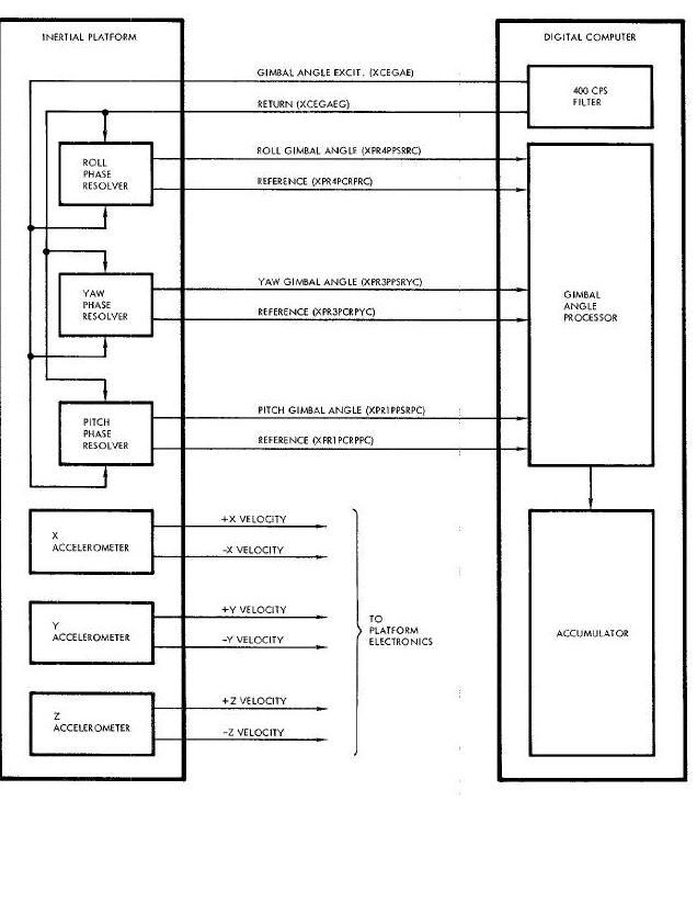
The following PRO instruction programming is associated with the Inertial Platform interface :
| Signal | Address | |
| X | Y | |
| Read pitch gimbal | 6 | 3 |
| Read roll gimbal | 6 | 4 |
| Read yaw gimbal | 6 | 5 |
The gimbal angles are read no sooner than 5 ms from each other, and the total reading time for all three angles is no greater than 30 ms. The angles are read once per computation in the catch-up, rendezvous, and re-entry modes, and once every 50 ms in the ascent mode. These angles are gated, as true magnitude, into the accumulator S, and I through 14 bit positions with the 15 through 25 bit
positions being zero. The accumulator value from the first PRO instruction is discarded. Each of the next three PRO instructions results in an accumulator value of the glmbal angle read by the previous PRO instruction, as follows:
(a) PROS6 (read pitch; process previously read angle)
(b) Discard previously read angle
(c) Wait 5 ms
(d) PR046 (read roll; process pitch)
(e) STO pitch
(f) wait 5 ms
(g) PRO56 (read yaw; process roll)
(h) STO roll
(i) wait 5 ms
(J) PRO36 (read pitch; process yaw)
(k) STO yaw
The computer inputs frcm the Inertial Platform are summarized follows:
(a) Roll gimbal angle (XPR4PPSRRC) and reference (XPR4PCRPRC)
(b) Yaw gimbal angle (XPR3PPSRYC) and reference ((XPR3PCRPYC)
(c) Pitch gimbal angle (XPRLPPSRPC) and reference (XPRIPCRPPC)
The computer output to the Inertial Platform is summarized as follows:
Gimbal angle excitation (XCEGAE) and return (XCEGAEG)
System Electronics (Figure below)
Outputs derived from each of the three platform accelerometers are supplied to the computer as incidental velocity pulses (+X and -X delta velocity, +Y and -Y delta velocity, and +Z and -Z delta velocity). An up level on one Line denotes a positive increment of velocity while an up level on the other line denotes a negative increment of velocity.
Computer- Platform Electronic Interface
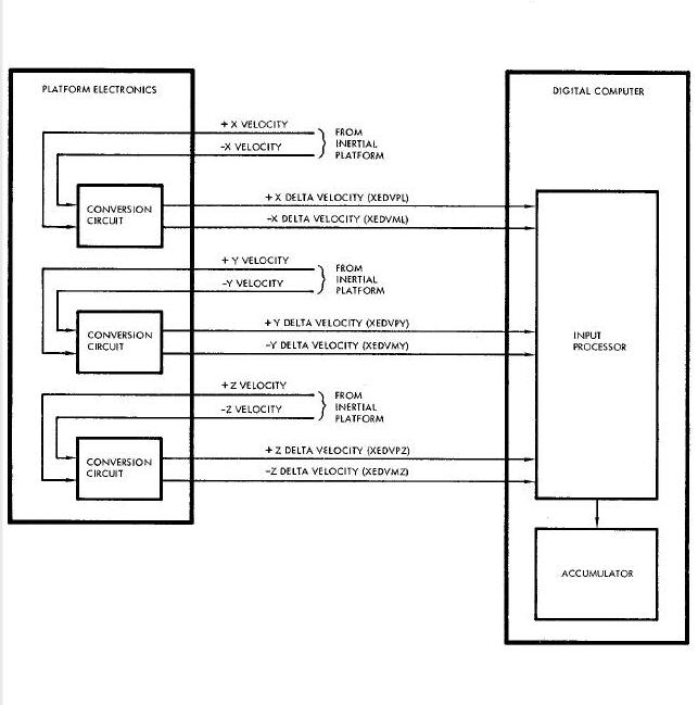
The following PRO instruction programming is associated with the System Electronics interface:
| Signal | Address | Processor | |
| X | Y | PHASETIME | |
| Read X delta velocity | 5 | 4 | 2 |
| Read Y delta velocity | 5 | 4 | 3 |
| Read Z delta velocity | 5 | 4 | 4 |
The input processor accumulates the incremental velocity pulses on the processor delay line in two 's-complement form. The velocity pulses have a maximum frequency of 3.6 kc per channel with a minimum separation of 135 usec between any plus and minus pulse for a given axis. Three input circuits are used to buffer the plus and minus pulses, one circuit for each axis. The buffered velocity pulse inputs are sampled during successive processor phases and read into a control circuit. This control circuit synchronizes the inputs with the processor timing and establishes an add, subtract, or zero control for the processor carry-borrow circuit. The accumulated velocity quantities are read into the accumulator S, and 1 through 12 bit positions in two's-complement form via a single PRO45 instruction as follows:
(a) Processor phase 2 - read accumulated X velocity
(b) Processor phase 3 - read accumulated Y velocity
(c) Processor phase 4 - read accumulated Z velocity
As the accelerometer values are read into the accumulator, the delay llne is automatically zeroed so that each reading represents the change in velocity from the previous reading.
The computer inputs from the System Electronics are summarized as follows:
(a) +X delta velocity (XEDVPL)
(b) -X delta velocity (XEDVML)
(c) +Y delta velocity (XEDVPY)
(d) -Y delta velocity (XEDVMY)
(e) +Z delta velocity (XEDVPZ)
(r) -Z delta veloclty (XEDVMZ)
IGS POWER SUPPLY (Figure Below)
The computer supplies a filtered 28 vdc signal to the IGS Power Supply to control the dc power supplied to the computer. The IGS Power Supply supplies power to the computer within 0.3 second after receiving the 28 vdc power control signal. When the computer power control signal drops to 2 vdc, the IGS Power Supply removes dc power from the computer within 0.3 seconds. The 26 vac, 4OO cps power furnished to the computer by the IGS Power Supply is not controlled by the computer power control signal, and is therefore present at the computer whenever the IGS Power Supply is operating.
Computer - Power Supply Interface Diagram
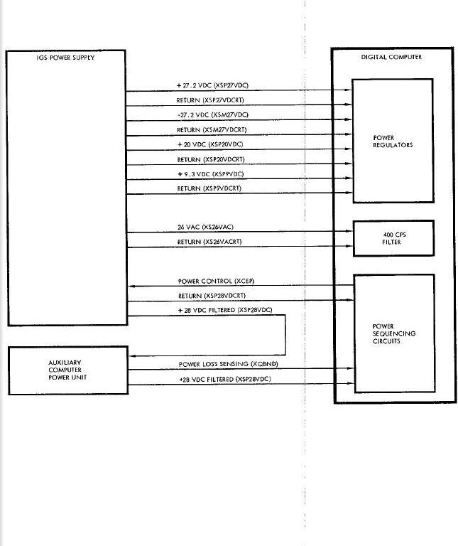
The computer inputs from the IGS Power Supply are summarized as follows:
(a) -27.2 vdc (XP27VDC) and return (XSP27VDCRT)
(b) -27.2 vdc (XSM27VDC) and return (XSM27VDCRT)
(c) -20 vdc (XSP20VDC) and return (XSP20VDCRT)
(d) +9.3 vdc (XSP9VDC) and return(XSP2VDCRT)
(e) 26 vac (XS26VAC) and return (XS26VACRT)
(f) +28 vdc filtered (XSP28VDC) and return (XSP28VDCRT)
The computer output to the IGS Power Supply is sumerized as follows:
Power Control (XCEP)
Auxiliary Computer Power Unit (ACPU) (Figure above)
The ACPU functions in conjunction with the IGS Power Supply to buffer power interruptions and depressions. When the ACPU senses a power interruption or depression, it supplies the power loss sensing signal to the power sequencing circuits in the computer. The ACPU then maintains the computer power constant until the power interruption or depression ends (up to a maximum of 100 msec). The computer output to the ACPU is summarized as follows:
- Power Control (XCEP)
The computer input from the ACPU is summarized as follows:
- Power loss sensing (XQBHD)
- +28 filtered Manual Data Insertion Unit (XSP28VDC)
Manual Data Insertion Unit (MDIU) (Figure Below)
The MDIU can insert into, and/or read out of, the computer up to 99 data words. It provides the crew with a means of updating certain data stored in the computer by inserting new data into the appropriate memory location.
Computer-MDIU Interface Diagram
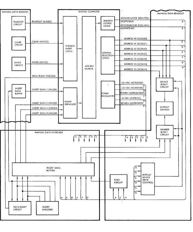
It also provides a capability to verify the data stored in a number of additional memory locations. Two of the quantities which may be inserted (TR and TX) are transferred to the Time Reference System by the computer, following insertion.
The MDIU consists of two units: The Manual Data Keyboard (MDK) and the Manual Data Readout (MDR). The MDK has a keyboard containing I0 push-button switches used during data insertion and readout. To insert data, the pilot always depresses seven data-insert push-button switches; the first two set up the address of the computer memory location in which data is to be stored, and the last five set up the actual data. Each digit inserted is also displayed for verification. Following the insertion and verification of the seventh digit, the ENTER push-button switch is pressed to store the data in the selected memory location. If verification of any digit cannot be made, the CLEAR push-button switch is pressed and the adress and data must be set up again. The MDR sequentially displays for verification the digits generated by the pilot. This unit can also be used to recheck quantities stored in the computer memory. This operation is accomplished by inserting and verifying only the first two (address) digits and then depressing the READ OUT push-button switch. The selected data is then displayed for verification. If the pilot attempts to insert data in an invalid address, attempts to read data out of an invalid address, inserts more than seven digits, or fails to insert a two-digit address prior to depressing the ENTER or READ OUT push-button switch, the seven digits displayed are all zero indicating a pilot error.
The following CLD instruction programming is associated with the MDIU interfaces;
| Signal | Address | |
| X | Y | |
| Data Ready | 1 | 0 |
| ENTER | 2 | 0 |
| READOUT | 3 | 0 |
| CLEAR | 4 | 0 |
The following PRO instruction programming is associated with the MDIU interface;
| Signal | Address | |
| X | Y | |
| Digit magnitude weight 1 | 0 | 3 |
| Digit magnitude weight 2 | 1 | 3 |
| Digit magnitude weight 4 | 2 | 3 |
| Digit magnitude weight 8 | 3 | 3 |
| Reset DIOI, DI02, ana DI03 | 0 | 4 |
| Display device drive | 1 | 4 |
| Digit select weight 1 | 0 | 5 |
| Digit select weight 2 | 1 | 5 |
| Digit select weight 4 | 2 | 5 |
| Read MDIU insert data | 3 | 4 |
The pilot must depress the CLEAR push-button switch for the first quantity to be inserted or displayed. Upon the recognition of DI04 on, the program sets DO4O off. Thls results in resetting DI01, DI02, and DI03,i and clearlng the MDIU buffer. The program then sets DO41 off to reset the display drivers.
When a digit push-button switch Is depressed, the Binary Coded decimal (BCD) is entered into the buffer and DIO1 is turned on. The program reads the buffer into accumulator blt positions 1 through 4 and sets D040 off. Followlng this, the program sends out a code by means of D050, D051, and D052 to select the digit to be displayed. The program then sets D041 on to turn the display drivers, and
sends a BCD digit to the buffer by means of D030, D031, D032, and D033. The program then waits 0.5 second and sets D040 and D041 off. The pilot must wait until the digit is displayed before entering the next digit. After all seven digits have been entered and displayed, the pilot depresses the push-button switch. This results in DIO2 being set on. The program then sets D040 off, and converts the five data digits to binary. This data is sealed and stored in memory according to the two-digit address.
To read data out of the computer the pilot enters the two-digit address of the quantity to be displayed and then depresses the READOUT push-button switch. This results in DI03 being set on. The computer then sets D040 off converts the requested
quantity to BCD, and sends the BCD data to the display buffer one digit at a time in 0.5-second intervals.
The computer inputs from the MDIU are summarized as follows;
(a) Readout (MZRC) - The up level of this signal denotes that the two previously inserted digits are to be used as the address of a
quantity to be displayed.
(b) Clear (XNZCC) - The up level of this signal denotes that the previously entered digit are incorrect and the insert sequence must
be repeated.
(c) Enter (XWZIC) - The up level of this signal denotes that the previously inserted digits have been verified and should be stored in
the computer memory.
(d) Data ready (XMZDA) - The up level of this signal denotes that a digit has been inserted. The computer samples this line at least
20 times per second to allow continuous insertion of data.
(e) Insert data 1, 2, 4, and, 8 (XNZR1, XMZB2, XMZB4, and XMZB8) - These four signals, denoteing one BCD character, are supllied to the computer for each decimal digit inserted.
The computer outputs to the MDIU are summarized as follows:
(a) Accumulator sign positive (XCDPOSAX) - The up level of this signal on a set input causes the addressed latch to be set.
(b) Accumulator sign negative (XCDNEGAX) - The up level of this signal on a reset input causes the addressed latch to be reset.
(c) Addressing - Seven lines provide the capability of addressing all latches in the MDIU. The following X iand Y address lines are provided:
(1) MDIU address XO (XCSAXO)
(2) MDIU address X1 (XCSAX1)
(3) MDIU address X2 (XCSAX2)
(4) MDIU address X3 (XCSAX3)
(5) MDIU address Y3 (XCSAY3)
(6) MDIU address Y4 (XCSAY4)
(7) MDIU address Y5 (XCSAYS)
By selecting one X and one Y address line at a time, a total of 12 addresses can be formed.
(d) Power - Regulated dc power is supplied to the MDIU as follows:
(1) +25 vdc (XCP 25VDC) and return (XCPM25VDCRT)
(2) -25 vdc (XCM25 VDC) and return (XCPM25VDCRT)
(3) +8 vdc (XCP8VDC) and return (XCP8VDCRT)
TIME REFERANCE SYSTEM (TRS) Figure 8-33 BELOW
The TRS counts Elapsed Time (ET) from lift-off through impact, counts down time to retrograde (TR) on command, and counts down time to equipment reset (TX) on command, all in I/8-second increments. The computer receives TR and TX data words from the MDIU end automatically transfers them to the TRS. When the computer receives a display request from the MDIU for TR, or when the computer program requires ET, the TRS transfers them to the computer.
Computer-TRS Interface Diagram
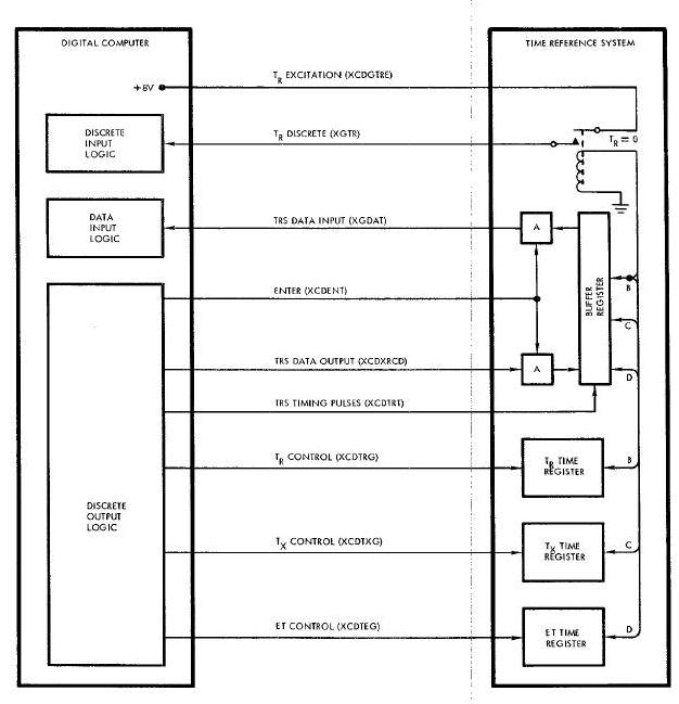
The following CLD instruction programming is associated with the TRS interface.
| Signal | Address | |
| X | Y | |
| TR discrete | 5 | 0 |
The following PRO instruction programming is associated with the TRS interface:
| Signal | Address | |
| X | Y | |
| ET control | 4 | 1 |
| TX control | 5 | 2 |
| TR control | 5 | 6 |
| Enter | 1 | 2 |
| TRS data and timing pulses | 0 | 2 |
| TRS control reset | 4 | 1 |
In the readout mode, the computer transfers TR or TX data words to the TRS. The mode is initiated by setting DO21 on. The 24 bits of data to be sent to the TRS are then placed in the accumulator by 24 consecutive sets of PRO20 and SHRI (shift right one place) instructions. With each PRO instruction, a timing pulse is automatically initiated 70 usec after the beginning of the data pulse. The
timing pulse is terminated so that its up level is 139 usec. After bit 24 has been sent to the TRS the program generates one of two control gates (TR or TX). Between 9 and 15 ms later, the computer terminates the TRS control gate.
The enter mode is initiated by setting D021 off. One of two control gates (ET or TR) is generated by the program and terminated between 9 and 15 ms later. After termination of the control gate, the program enters a subroutine consisting of consecutive sets of PRO1O and SHR1 instructions. Every time a PRO operation is called for, a timing pulse is generated by the same logic as in the readout mode. The timing pulse is sent to the TRS to cause the addressed data to be supplied to the computer. The first bit received is discarded wlth the final SHR1 instruction. The second bit received is the least significant bit and is shifted into accumulator bit position 25 at the completion of the twenty-fifth set of PRO20 and SHR1 instructions. When TR equals zero, a relay in the TRS connects the excitation line to the TR discrete line. The TR discrete signal then causes the computer to start re-entry calculatlons.
The computer inputs from the TRS are summerized as follows:
(a) TR discrete (XGTR) - The up level of this signal signifies that the computer should begin re-entry calculations.
(b) TRS data input (XGDAT) - All data transfers from the TRS to the computer occur on this line. The data word on the llne is determined by which control gate the computer actuates prior to the actual data transfer. The up level is a binary 1 .
The computer outputs to the TRS are summerized as follows:
(a) TR excitation (SCDGTRE) - The computer supplies +8 vdc through a resistor to the TRS as the TR excitation input. When TR equals
zero, the TR relay causes the TR excitation input to be transferred to the computer as the TR discrete signal.
(b) Enter (XCDENT) - The up level of this signal signifies that data is to be transferred from the TRS to the computer when the transfer clocks occur. The down level signifies that data is to be transferred from the computer to the TRS.
(c) TRS data output (XCDXRCD) - All data transfers from the computer to the TRS occur on this line. The data word on the line is determined by which control gate (TR or TX) the computer has actuated. The up level is a binary 1.
(d) TRS timing pulses (XCDTRT) - These 3.57 kc timing pulses cause the computer data to be shifted into or out of the TRS buffer register for transfer to or from the computer.
(e) TR control (XCDTRG) - The up level of this signal causes the transfer of data between the TRS buffer register and the TRS TR register. The direction of transfer is determined by the level of the enter signal.
(f) TX control (XCDTXG) - The up level of ithis signal causes the transfer of data between the TRS buffer register and the TRS TX register. The direction of transfer Is determined by the level of the enter signal.
(g) ET control (XCDTRG) - The up level of this signal causes the transfer of data between the TRS buffer register and the TRS ET register. The direction of transfer is determined by the level of the enter signal.
Digital Command System, DCS (Figure Below)
The DCS accepts BCD messages from the ground stations at a 1 kc rate, decodes the messages, and routes the data to either the TRS or the computer. In addition, the DCS can generate up to 64 discrete commands.
| Signal | Address | |
| X | Y | |
| DCS ready | 6 | 0 |
Computer-DCS Interface Diagram
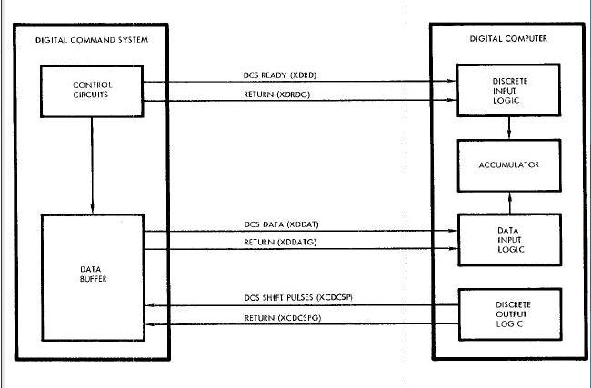
The following PRO instruction programming is associated with the DCS interface:
| Signal | Address | |
| X | Y | |
| Computer ready | 1 | 0 |
| DCS shift pulse gate | 0 | 0 |
When data is to be sent to the computer, the DCS supplies the computer with a DCS ready discrete input (DI06). This input is sampled very 50 ms or less in all computer modes except during the 1/8-second interval in the ascent mode when reading ET at lift-off. To receive DCS data, the computer supplies a series of 24 DCS shift pulses at a 500 kc repetition rate by setting D001 off and programming a PROO instruction. These shift pulses cause the data contained in the DCS buffer register to be shifted out on the DCS data line and read into accumulator bit positions 1 through 24, with position 19 through 24 containing the assigned address of the associated quantity and position 1 through 18 containing the quantity. Bit position 19 (address portion) and bit position 1 (data portion) are the most significant bits.
The computer inputs from the DCS are summarized as follows:
(a) DCS ready (XDRD) and return (XDRDG) - The down level of this signal signifies that the DCS is ready to transfer data to the computer.
(b) DCS data (XDDAT) and return (XDDATG) - This serial data from the DCS consists of 24 bits, with 6 being address bits and 18 being
data bits.
The computer output to the DCS is summarized as follows:
(a) DCS shift pulses (XCDCSP) and return (XCDCSPG) - The computer supplies these 24 shift pulses to the DCS to transfer data contained in the DCS buffer register out on the DCS data llne.
Rendezvous Radar (Figure Below)
The Rendezvous Radar supplies the computer with three data inputs: line-of -sight range to target, sine of azimuth, and sine of elevation. In the rendezvous mode, the computer uses radar data to compute and display velocity to be gained (in body coordinates).
Computer-Radar Interface Diagram
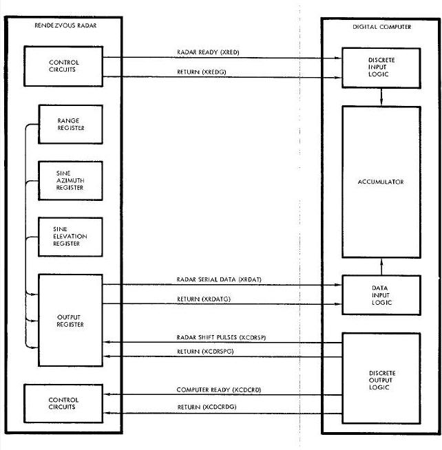
The following CLD instruction progr_mlng is associated with the Rendezvous Radar interface:
| Signal | Address | |
| X | Y | |
| Radar ready | 0 | 0 |
The following PRO instruction programing is associated with the Rendezvous Radar interface:
| Signal | Address | |
| X | Y | |
| Computer ready | 1 | 0 |
| Reset radar ready | 3 | 6 |
| DCS shift pulse gate | 0 | 0 |
When the computer requires radar data, the computer ready discrete output (DOO1) is supplied to the Rendezvous Radar. Prior to this, the program has reset the radar ready discrete input buffer with the PR063 instruction. The computer ready signal causes the radar to stop updating its internal data and to enter a hold mode following completion of a data acquisition cycle. The program waits 20 ms
and tests the radar ready discrete input (DI00). If the test is negative, three consecutive sets of PR000 and STO instructions are given. Each PRO instruction causes a burst of fifth-two 500 kc pulses to be sent to the radar to shift out the contents of the radar data output register. The data appears in the output register in the following sequence:
(a) Range - 15 bits
(b) Sine azimuth - 10 bits
(c) Sine elevation - 10 bits
A delay of 280 usec occurs before the leading pulse of each 500 kc burst to enable the computer to store the data it has received and to allow the next data word to be inserted into the radar data output register in preparation for transmission to the computer.
Radar range data is read in true magnitude form into accumulator bit positions 8 through 24. If bit positions 8 through 11 (four most significant bits) are 1's, the radar rate data is considered unreliable and is ignored. Sine azimuth and sine elevation data are read into accumulator bit positions 15 through 24.
The computer inputs from the Rendezvous Radar are summarized as follows:
(a) Radar ready (XRED) and return (XREDG) - The up level of this signal signifies that the radar has recognized the computer ready signal and is ready to transfer data. The radar ready pulse occurs between 0 and 4000 usec after the computer ready pulse, if radar lock-on has occurred.
(b) Radar serial data (XRDAT) and return (XRDATG) - This data consists of three words which occur in a fixed format as determined by the radar shift pulses. The first word is range to target (15 bits), the second word is sine of azimuth angle (10 bits), and the third
word is sine of elevation angle (10 bits).
The computer outputs to the Rendezvous Radar are summarized as follows:
(a) Radar shift pulses (XCDRSP) and return (XCDRSPG) - These 500 kc pulses are issued between 280 usec and 5 millisec after the computer receives the radar read signal. They are sent out as three groups of 52 pulses each, with a 280 usec delay before the leading edge of each group.
(b) Computer ready (XCDCRD) and return (XCDCRDG) - The up level of this signal signifies that the computer requires radar data inputs.
Attitude Display/Attitude Control add Maneuver Electronics (ACME) (Figure Below)
During the ascent mode, the computer generates pitch, roll, and yaw attitude error signals and supplies them to the Attitude Display. The pilot utilizes the Attitude Display to monitor the performance of the ascent guidance equipment.
Computer-Attitude Display/ACME Interface Diagram
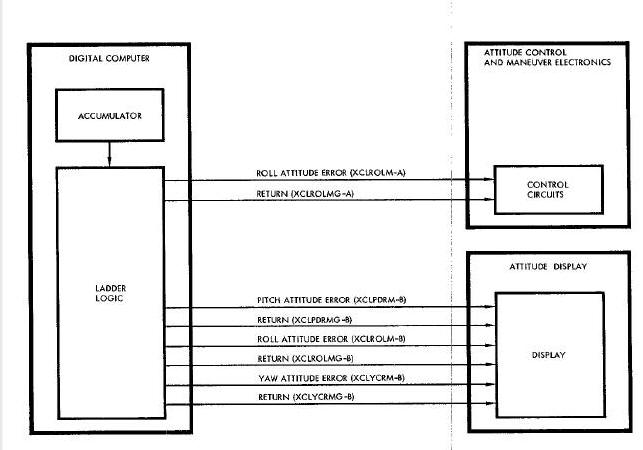
During the catch-up and rendezvous modes, the computer generates pitch and yaw attitude error signals and is capable of supplying them to the Attitude Display and the ACME.
During the re-entry mode, the computer generates a roll attitude error or bank rate signal and supplies it to the Attitude Display and the ACME. If range to touchdown with zero lift is equal to the computed range to the desired touchdown point, a bank rate command equivalent to a 15 degree per second roll rate is provided on the roll attitude error output line. If the range to touchdown with zero lift is not equal to that for the desired touchdown point, the appropriate roll rate or roll attitude signal is supplied on the output line. Also, during the re-entry mode, the computer generates cross range end down range error signals and supplies them to the Attitude Display for the pilots' use in mannually controlling the re-entry flight path of the spacecraft.
The following PRO instruction programing is associated with the Attitude Display and ACME interfaces:
| Signal | Address | |
| X | Y | |
| Pitch error command | 7 | 0 |
| Yaw error command | 7 | 1 |
| Roll error command | 7 | 2 |
| Pitch resolution | 2 | 0 |
| Yaw resolution | 3 | 0 |
| Roll resolution | 4 | 0 |
The pitch, yaw, and roll error commands are written into a seven-bit register from accumulator bit positions S, and 8 through 13 with a PRO instruction having an X address of 7. The outputs of the register are connected to ladder decoding networks which generate a dc voltage equivalent to the buffered digital error. This analog voltage is then sampled by one of three sample and hold circuits; while one circuit is sampling the ladder output, the other two circuits are holding their previously sampled value. The minimum sample time is 2 ms, and the maximum hold time is 48 ms. The Y address of the previously mentioned PRO instruction selects the one sample and hold circuit that is to sample the ladder output. The output of each sample and hold circuit is fed into an individual ladder amplifier where the DC analog voltage for each channel is made available for interfacing with the Titan Autopilot.
The dc analog outputs are also fed through individual range switches and magnetic modulators where the dc voltages are converted to 400-cycle analog voltages. The range switches, which are controlled by means of discrete outputs, can attenuate the dc voltages being fed into the magnetic modulators by a factor of 6-to-1. The addressing of the discrete outputs for controlling the range switches is as follows:
(a) Pitch or down range error (D002) - plus for low range; minus for high range.
(b) Yaw or cross range error (DO03) - plus for low range; minus for high range.
(c) Roll error (D004) - plus for low range; minus for high range.
The error commands are written every 50 ms or less. The updating period, however, The error commands are written every 50 ms or less. The updating period, however, The error commands are written every 50 ms or less. The updating period, however, is dependent upon the computer mode of operation. For the catch-up, rendezvous, and re-entry modes (and the orbital insertion phase of ascent guidance), the error commands are updated once per computation cycle or every 0.5 second or less. For first and second stage ascent guidance, the error co_nds are updated every 50 ms or less.
The computer outputs to the Attitude Display and ACME are summarized as follows:
(a) Pitch attitude error (SCLPDRM) and return (XCIPDRMG) - Two identical sets of outputs (A and B) are time-shared between
pitch attitude error (during ascent, catch-up and rendezvous) and down range error (during Re-entry).
(1) Pitch attitude error (ascent) to Attitude Display
(2) Pitch attitude error (catch-up and rendezvous) to Attitude Display
(3) Down range error (re-entry) to Attitude Display
(b) Roll attitude error/bank rate command (XCLROLM) and return (XCIROLMG) - Two identical sets of outputs (A and B) are timeshared
between roll attitude error and bank rate command. During ascent, it represents only roll attitude error. During re-entry, however, it represents roll attitude error when the computed range is less than the desired range, and a 20 degree per second bank rate command when the computed range equals or exceeds the desired range.
(1) Roll attitude error (ascent) to Attitude Display
(2) Roll attitude error (re-entry) to Attitude Display and ACME
(3) Bank rate comand (re-entry)to Attitude Display and ACME
(c) Yaw attitude error (XCLYCRM) and return (XCLYCRMG) - Two identical sets of outputs (A and B) are time-shlred between yaw attitude error (during ascent, catch-up, and rendezvous) and cross range error (during re-entry).
(1) Yaw attitude error (ascent) to Attitude Display
(2) Yaw attitude error (catch-up and rendezvous) to Attitude Display
(3) Cross range error (re-entry) to Attitude Display
Titan Autopilot (Figure Below)
During ascent, the computer performs guidance computations in parallel with the Titan guidance and control system. If a malfunction occurs in the Titan system, the pilot can switch control to the Inertial Guidance System. For a description of the program requirements and operation associated with the Titan Autopilot interface, refer to the Attitude Display and ACME interface description.
Computer-Autopilot Interface Diagram
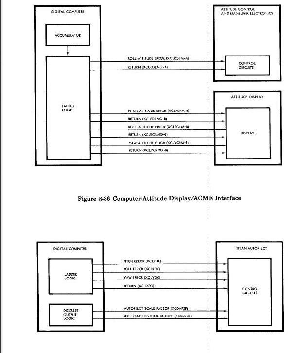
The computer outputs to the Tital Autopilot are summarized as follows:
(a) Pitch error (XCLPDC) - These signals are provided during backup ascent guidance.
(b) Roll error (XCLRDC) - These signals are provided during backup ascent guidance.
(c) Yaw error (XCLYDC) - These signals are provided during backup ascent guidance.
(d) Common Return (XCLDCG)- These signals are provided during backup ascent guidance.
(e) Autopilot scale factor (XCDAPSF) - This signal changes the autopilot dynamics after the point of maximum dynamic pressure is
reached.
(f) Second stage engine cutoff (XCDSSCF) - This signal is generated when velocity to be gained equals zero.
Auxiliary Tape Memory (ATM) (Figure Below)
The ATM is interfaced with the Digital Computer and the following controls and indicators on the Pilots' Control and Display Panel (PCDP):
ATM mode switch
ATM 0N/RESET switch
ATM ERROR indicator
ATM RUN indicator
The crew, via the PCDP and the computer, controls the modes of ATM operation. The Incremental Velocity Indicator (IVI) and the ATM ERROR and RUN indicators are used to provide information on ATM status. The crew also uses the Manual Data Insertion Unit (MDIU) for commuication with the computer and subsequent computer commuicatioin with the ATM.
The following CID instruction programming is associated with the ATM interface;
| Signal | Address | |
| X | Y | |
| ATM clock | 1 | 4 |
| ATM on | 3 | 3 |
| ATM data channel 2 | 3 | 4 |
| ATM mode control number 1 | 4 | 1 |
| ATM beginning or end of tape | 4 | 3 |
| ATM data channel 3 | 4 | 4 |
| ATM mode control number 2 | 5 | 1 |
| ATM data channel 1 | 5 | 3 |
Computer-ATM-PCDP Interface (S/C 8 thru 12 Only)
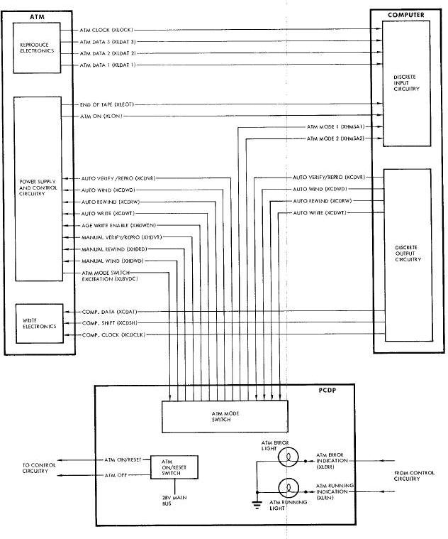
The following PRO instruction programming is associated with the ATM interface:
| Signal | Address | |
| X | Y | |
| ATM wind/rewind reset | 4 | 1 |
| ATM verify/reprogram command | 4 | 4 |
| ATM wind command | 5 | 1 |
| ATM rewind command | 5 | 2 |
The computer inputs from the ATM are minimrized as follows:
(a) ATM clock (XLOCK) - A two millisecond pulse for each three-bit parallel data output frame, delayed 1520 microseconds from the
nominal beginning of each frame. Up level six to twelve volts; down level less than one volt. Rise and fall times less than 20 microseconds each.
(b) ATM data 1 (XLDAT 1), data 2 (XLDAT 2), data 3 (XLDAT 3) - Parallel NRZ data output on three lines at a rate of 200 bits per second on each line. Individual bit periods are written +/- 2% of normal. Other specifications same as for data outputs.
(c) End-of-tape (XLEOT) - A logic level from the ATM to the computer. An up level indicates that either end of the tape has been reached.
(d) ATM on (XLON) - A logic signal from the ATM to the computer. An up level indicates that the ATM has reached proper operating speed in the read and write modes. This signal appears approximately five seconds after a command is given to the AS to read or write. It is inhibited when either lend of the tape is reached.
The computer outputs to the AS are summarized as follows:
(a) Auto verify/reprogram (XCDVR) - A command line from the computer, through the AUTO position of the AT TAPE mode switch, to the ATM. An 8 vdc signal on this line causes the AS to operate in the record or write mode in the forward direction at a nominal tape speed of 1. 5 ips.
(b) Auto wind (XCDWD) - An 8 vdc signal from the computer through the AUTO position of the AUX TAPE mode witch, to the ATM. This signal causes the tape to move in the forward direction at a nominal tape speed of 12 ips. The AS functions internally in the read mode during this operation.
(c) Auto rewind (XCDRW) - An 8 vdc signal from the computer, through the AUTO position of the AUX TAPE mode switch, to the AS. This signal causes the tape to move in the reverse direction at a nominal tape speed of 12 ips.
(d) Auto write (XCDWT) - A signal from the computer, through the AUTO position of the AUX TAPE mode switch, to the ATM. The signal is used by the ATM to set up internal controls such that computer data can be recorded on the tape.
(e) Computer data (XCDAT) - Groups of four serial NRZ data bits, each group or frame totaling 1120 microseconds duration at a rate of 200 frames per second. Up level greater than seven volts; down level less than one volt. Rise time less than 15 microseconds;
fall time less than ten microseconds.
(f) Computer shift (XCDSH) - Groups of four serial pulses, each pulse having a period of 139 microseconds and spaced 141 microseconds from the next pulse. Shift input pulses begin 70 microseconds after the start of the data pulses. Up level greater than seven volts; down level less than one volt. Rise time less than 15 microseconds; fall time less than 0.4 microseconds.
(g) Computer clock (XCDCLK) - Serial pulses having a duration of 18 microseconds each at a rate of 200 pulses per second or one per
frame. These pulses are delayed 280 or 560 microseconds after the beginning of bit number four in each frame. Up level is seven to
14 volts; down level less than one volt. Rise time less than ten microseconds; fall time less than O. 5 microseconds.
Additional ATM - PCDP and PCDP - Computer interfaces are summarized as follows :
(a) ATM mode switch excitation (XL8VDC) - A nominal 8 vdc excitation voltage from the ATM to the AUX TAPE mode switch on the PCDP.
(b) AGE write enable (XHDWEN) - An 8 vdc discrete from the ATM, through the STANDBY position of the AUX TAPE mode switch, to the AGE to enable it to send a write command to the ATM.
(c) Manual verify/reprogram (XHDVR) - An 8 vdc discrete from the AUX TAPE mode switch to the A_ which causes the ATM to operate in the write mode at a nominal tape speed of 1.5 ips.
(d) Manuel wind (XHDWD) - An 8 vac discrete from the AUX TAPE mode switch to the ATM which causes the tap to move in a forward
direction at a nominal tape speed of 112 ips.
(e) Manual rewind (XHDRD) - An 8 vdc discrete from the AUX TAPE mode switch to the ATM which causes the tape to move in the reverse direction at a nominal tape speed of 12 ips.
(f) ATM on/reset - A momentary 28 vdc signal from the AUX TAPE OFF-ON/RESET switch to the ATM. This signal will either initiate
ATM operation (apply power) or re-initiate operation while extinguishing the ADX TAPE ERROR indicato r on the PCDP.
(g) ATM OFF - A momentary 28 vdc signal from the AUX TAPE OFF-ON/RESET switch to the ATM. It causes the ATM to cease operation.
(h) An error indication (XLERR) - A signal from the ATM to the PCDP When ever the error detection logic circuits in the ATM indicate
a disagreement between the recorded parity bits and the parity bits that are generated from the data during playback at either
tape speed. The signal causes the AS ERROR indicator on the PCDP to illuminate.
(j) ATM running indication (XLRN) - A signal from the ATM which is transmitted to the PCDP five seconds after the ATM is commanded
to operate in any mode. This signal illuminates the ATM RUN indicator on the PCDP whenever the tape is in motion. The signal is terminated when either end of the tape is reached.
(k) Two mode controls (XHMSA1 and XHMSA2) - Mode control signals supplied to the computer from the AUX TAPE mode switch on
the PCDP. The signals define the ATM mode selection.
| MODE POSITION | XHMSA1 | XHMSA2 |
| AUTO | 1 | 1 |
| REPRO | 0 | 1 |
| All Others | 0 | 0 |
Pilots' Control and Display Panel (PCDP) (Figure below )
The following CLD instruction programming is associated with the PCDP interface:
| Signal | Address | |
| X | Y | |
| Computer mode 1 | 1 | 1 |
| Computer mode 2 | 0 | 1 |
| Computer mode 3 | 3 | 1 |
| Start computation | 1 | 2 |
| Abort transfer | 7 | 1 |
| Fade-in discrete | 6 | 1 |
Computer - PCDP Interface Diagram
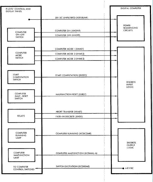
The following PRO instruction programming is associated with the PCDP interface:
| Signal | Address | |
| X | Y | |
| Computer malfunction | 4 | 3 |
| Computer running | 5 | 0 |
| Reset start computation | 2 | 6 |
The computer inputs from the PCDP are summarized follows:
(a) Computer on (XHONP) and computer off (XHOFF) - These signals from the COMPUTER ON-OFF switch control computer power.
(b) Computer mode - The computer receives three binary coded discrete signals from the COMPUTER mode switch, to define the following operational modes:
| Mode | Computer Mode 1 (XHMS1) |
Computer Mode 2 (XHMS2) |
Computer Mode 3 (XHSM3) |
| Pre -launch | 0 | 0 | 1 |
| Ascent | 0 | 1 | 0 |
| Catch-up | 0 | 1 | 1 |
| Rendezvous | 1 | 0 | 0 |
| Re -entry | 10 | 0 | 1 |
(c) Start computation (XHSTC) - This signal from the START pushbutton switch starts the closed-loop rendezvous operation and
initiates re-entry calculations.
(d) Malfunction reset (XHRST) - This signal from the computer malfunction RESET switch resets the c_uter malfunction latch. The
pilot uses the switch to test for a transient failure.
(e) Abort transfer (XHABT) - The signal automatlcally switches the computer from the ascent mode to the re-entry mode.
(f) Fade-in descrete (XHSFI) - This signal from a relay is supplied to the acmulator via the discrete input logic.
(g) 28 vdc unfiltered (XFP28UNF)
The computer outputs to the PCDP are summarized as follows:
(a) Computer running (XCDCOMP) - This program-controlled signal lights the computer running lamp which is used as follows:
(1) Pre-launch: The COMP (computer running) lamp remains off during this mode, except during mission simulation when its operation is governed by the mode being simulated.
(2) Ascent: The COMP lamp turns on following Inertial Platform release. The lamp remains on for the duration of the mode, and then turns off.
(3) Catch-up: The COMP lamp lights after the START pushbutton switch is depressed. The lamp remains on for the duration of the mode, and then turns off.
(4) Rendezvous: The COMP lamp lights after the START pushbutton switch is depressed. For the remainder of the mode, operation of the 1 Amp is dictated by the radar readings that occur in this mode. The lamp turns off when the mode is terminated.
(5) Re-entry: The COMP lamp lights when the START pushbutton switch is depressed or when time to start re-entry calculations is equal to zero. The lamp remains on for the duration of the mode, and then turns off.
(b) Computer malfunction (XCDMAL-A) - This signal turns on the computer MALF lamp. Either the computer diagnostic program, a
built-in timing check, or an AGE command actuates the signal.
(c) Switch excitation (SXDHSME) - This dc excitation is suppled to the COMPUTER mode switch, the START computation switch and the malfunction RESET switch.
Incremental Velocity Indicator (IVI) (Figure Below)
The IVI contains three incremental velocity counters that display velocity increments along the spacecraft (body) axes.
Power is applied to the IVI whenever the computer is turned on. During the first 30-second period (or less) following the application of power, the IVI automatically references its counters to zero. After this period, the IVI is capable of recognizing computer signals.
Computer-IVI Interface Diagram
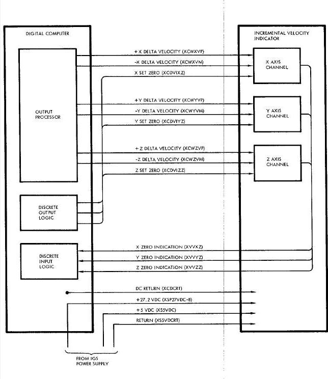
The IVI counters can be set manually by means of control knobs on the front of the unit, or they can be set automatically by the computer. After the counters are initally set, they are driven by incremental velocity pulses from the computer. These pulses are used to update the indications displayed by the counter. The computer can set the individual counters to zero by providing a 20 usec pulse on each of three set zero lines. A feed-back signal, denoting zero counter position, limits the computer to test for the proper counter reference prior to the insertion and dlsplay of a computed velocity increment.
The following CLD instruction programming is associated with the IVI interface:
| Signal | Address | |
| X | Y | |
| X zero indication | 1 | 3 |
| Y zero indication | 5 | 2 |
| Z zero indication | 6 | 2 |
| Velocity error count not zero | 2 | 2 |
The following PRO instruction programing is associated with the IVI interface:
| Signal | Address | |
| X | Y | |
| Select X counter | 2 | 1 |
| Select Y counter | 3 | 1 |
| Drive counters to zero | 1 | 1 |
| Write output processor | 5 | 3 |
The computer supplies three signals to the IVI, one for each counter, that are used to position the counters to zero. To generate these signals, the program sets DO11 minus and sets DO12 and D013 as follows:
| Signal | D012 | D013 |
| X set zero | Minus | Plus |
| Y set zero | Plus | Minus |
| Z set zero | Minus | Minus |
The IVI provides three feed-back signals to the cc_uter (DI31, D.125, and D126) to indicate that the counters are zeroed. The program tests the individual counters for zero position before attempting to drive them to zero.
The output processor provides a timed output to the IVI that represents velocity increments along the spacecraft axes. One output channel (phase 2) on the delay line is time-shared among the X, Y, and Z counters. Incremental velocities (in two's-complement form) are written on the delay line during phase 2 from accumulator bit positions S and 1 through 12. Discrete joutputs DOI2 and DOI3, which are set no more than 1 ms before the PRO35 operation, select the proper velocity signal as follows:
| Signal | D012 | D013 |
| X velocity | Minus | Plus |
| Y velocity | Plus | Minus |
| Z velocity | Minus | Minus |
Once data is written on the delay line, the output Of the delay line is sensed for data during bit times BTI through BTI2. Any bit sensed during this time indicates the presence of data which is theen gated into a buffer along with the sign bit (BT13) during phase 2. This buffer is sampled approximately every 21.5 ms and a pulse is generated if the buffer is set either plus or minus. During this
same time, an update cycle is initiated and a count of one is either added to or subtracted from the delay line data to decrease the magnitude by a count of one. If the buffer is set to zero during the update cycle, the data on the delay line is recirculated without affecting its magnitude. The zero output of the buffer is addressed as D122. When this discrete input is off, velocity data has been counted down to zero and the next velocity can be processed.
The computer inputs from the IVI are summarlzed as follows:
(a) X zero indication (XVVXZ) - The down level signifies that the X channel of the IVI is at the zero position.
(b) Y zero indication (XVVYZ) - The down level signifies that the Y channel of the IVI is at the zero position.
(c) Z zero indication (XVVZZ) - The down level signifies that the Z channel of the IVI is at the zero position.
The computer outputs to the M are summarized as follows:
(a) +X delta velocity (XCWXVP) - The up level denotes that the X channel should change by one foot per second in the fore direction.
(b) -X delta velocity (XCWXVM) - The up level denotes that the X channel should change by one foot per second in the aft direction.
c) X set zero (XCDVIXZ) - The up level drives the X channel to the zero position.
(d) +Y delta velocity (XCWYVP) - The up level denotes that the Y channel should change by one foot per second in the right direction.
(e) -Y delta velocity (XCYVM) - The up level denotes that the Y channel should change by one foot per second in the left direction.
(f) Y set zero (XCDVIYZ) - The up level drives the Y channel to the zero position.
(g) -Z delta velocity (XCWZVP) - The up level denotes that the Z channel should change by one foot per second in the down direction.
(h) -Z delta velocity (XCWZVM) - The up level denotes that the Z channel should change by one foot per second in the up direction.
(i) Z set zero (XCDVIZZ) - The up level drives the Z channel to the zero position.
Instrumentation System (Figure Below)
The computer is interfaced with the multiplexer encoder unit and the signal conditioning equipment of the Instrumentation System. COntinuous analog data is provided to the signal conditioning equipment, and stored digital quantities are sent upon request to the multiplexer encoder unit.
Certain computer data, as described below, is continually made available to the signal conditioning equipment. The signal conditioning equipment conditions this data for multiplexing and analog-to-digital conversion by the multiplexer encoder unit.
Computer-IS Interface Diagram
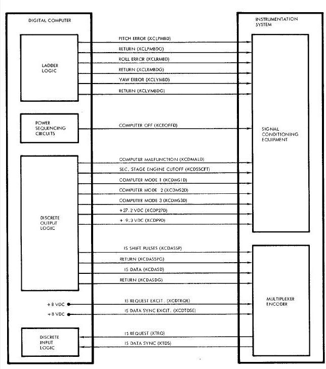
(a) Computer modes - The mode signals transmitted to the computer are monitored to determine that the computer was in the correct mode for a partlcularoperational mission phase.
(b) Computer input power - The 27.2 vdc and 9.3 vdc inputs supplied to the computer by the IGS Power Supply are monitored via the computer.
(c) Computer running - The computer running discrete output is monitored and recorded.
(d) Computer malfunction - The computer malfUnction discrete output is monitored and recorded.
(e) Attitude errors: The pitch, yaw, and roll ac analog attitude errors are monitored and recorded.
Twenty-one data word locations in the computer memoryiare allocated for the storage of Instrumentation System data. Data stored in these locations is dependent upon the computer mode of operation.
The following CLD instruction programming is associated with the Instrumentation System interface:
| Signal | Address | |
| X | Y | |
| Instrumentation System request | 7 | 0 |
| Instrumentation System sync | 2 | 1 |
The following PRO instruction programing is associated with the Instrumentation System interface:
| Signal | Address | |
| X | Y | |
| Instrumentation System Control Gate | 0 | 1 |
Every 50 ms or less, the computer program tests the Instrumentation System request discrete input (D107). If the discrete input is tested minus, the Instrumentation System sync discrete input (D112) is tested as follows:
(a) D112 minus - The program stores current specified values, according to the computer mode, in an Instrumentation System memory buffer of 21 locations. The contents of the first buffer location are placed in the accumulator so that the sign position of the data word corresponds to the sign position of the accumulator. Then a PRO10 in instruction is given. This instruction causes the information contained in accumulator bit positions S, and 1 through 23 to be supplied to the Instrumentation System. Twenty-four shift pulses are also supplied to the Instrumentation System.
(b) D112 plus - An Instrumentation System program counter is incremented by one and the contents of the next sequential buffer location are placed in the accumlator and sent to the Instrumentation System via the PRO10 instructions. Subsequent Instrumentation System requests advance the program counter until all 21 Instrumentation System quantities are tranmuitted.
The computer inputs from the Instrumentation System are svmmarized as follows:
(a) Instrumentation System request (XTRQ) - An up level on this line signifies that the Instrumentation System requires a computer data word. The word is transferred from the computer within 75 ms of the request. Requests can occur at rases up to I0 times per second.
(b) Instrumentation System data sync (XTDS) - An up level on this line signifies the beginning of the Instrumentation System data transfer operation.
The computer outputs to the Instrumentation System are summarized as follows:
(a) Instrumentation System shift pulses (XCDASSP) and return (SCDASSPG) This series of 24 pulses causes Instrusentation System data to be transferred to the Instrumentation System buffer.
(b) Instrumentation System data (SCDASD) and return (XCDASDG) - These 24 bits of data are transferred1in synchronism with the Instrumentation System shift pulses.
(c) Instrumentation System request excitatlon (SCDTRQE) - This +8 vdc signal is the excitation for the Instrumentation System request signal.
(d) Instrumentation System data sync excitation (SCIEDSE) - This +8 vdc signal is the excitation for the Instrumentation System data sync signal.
(e) Monitored signals - The following signals are supplies to the Instrumentation System for monitoring purposes:
(1) Pitch error (XCLPMRD) and return (XCLPMBDG)
(2) Roll error (SCLRMBD) and return (XCLRMBDG)
(3)Yaw error (XCLYMBD) and return (XCLYMBDG)
(4) Computer off (XCEOFFD)
(5) Computer malfuctotlon (XCDMALD)
(6) Second stage engine cutoff (XCDSSCFD)
(7) Computer mode 1 (XCDMSID)
(8) Computer mode 2 (XCDMS2D)
(9) Computer mode 3 (XCSMSSD)
(10)+27.2 vdc (XCDP27D)
(11) +9.3 vdc (XCDP9D)
Aerospace Ground Equipment (AGE) (Figure Below)
The AGE determines spacecraft-installed computer status by being able to read and display the contents of any memory location, initiate and terminate marginal tests of the memory timing, and command the computer to condition the computer malfunction circuit. These tests are accomplished by a hard-wlred computer/AGE data llnk.
Computer-AGE Interface Diagram
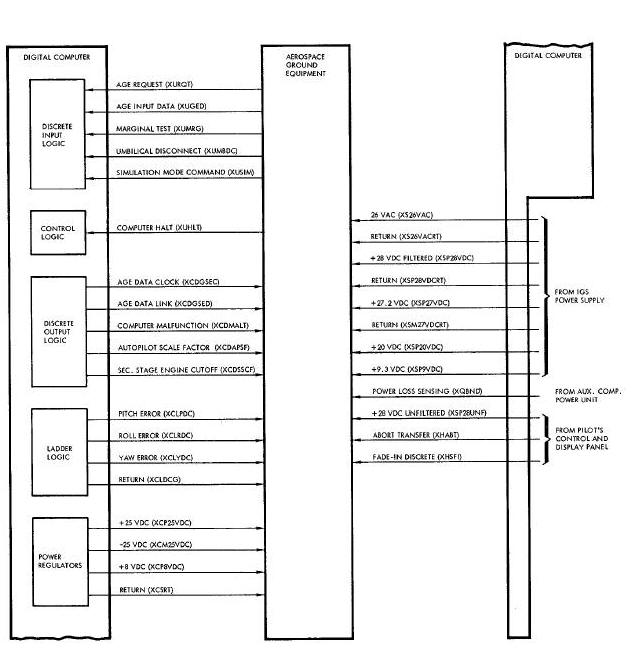
In conjunction with a voice link to the spacecraft, the AGE can control the various computer modes of operation to determine the status of the computer and its interfaces. To aid in localizing failures, the AGE monitors the following computer signals:
(a) All input and output voltages - (to Titan Autopilot)
(b) Second stage engine cutoff - (to Titan Autopilot)
(c) Autopilot scale factor - (to Titan Autopilot)
(d) Roll error command - (to Titan Autopilot)
(e) Yaw error command - (to Titan Autopilot)
(f) Pitch error command - (to Titan Autopilot)
(g) Computer malfunction - (to Titan Autopilot)
In addition, the AGE provides two hard-wlred inputs to the computer to reset the malfunction circuit and halt the computer and to force a marginal check of the memory t_m!ng. Early and late strobing of the memory iis effected using the cornputer/AGE data link.
The following CLD instruction programming is associated with the AGE interfaces:
| Signal | Address | |
| X | Y | |
| AGE request | 2 | 3 |
| AGE input data | 7 | 2 |
| Simulation mode Command | 4 | 2 |
| Umbilical Disconnect | 6 | 3 |
The following PRO instruction programming is associated with the AGE interface:
| Signal | Address | |
| X | Y | |
| AGE data link | 2 | 2 |
| AGE data clock | 3 | 2 |
| Computer Malfunction | 4 | 3 |
| Memory strobe | 0 | 6 |
| Autopilot scale factor | 1 | 6 |
| Second stage engine cutoff | 4 | 6 |
The AGE program commences when the AGE request (C132) is tested minus. To receive the 18 bit AGE data word, the program repeats the following sequence of operations 18 times:
(a) Turn on AGE data clock (D023)
(b) Wait 2.5 ms
(c) Reset AGE data clock (D023)
(d) wait 1.5 ms
(e) Read AGE input data (DI27)
(f) wait 1.5 ms
The above sequence causes the 18-bit AGE word to be shifted out of the AGE register and Into the computer. The first 4 bits of the AGE word are mode bits, and the remaining bits are data. The coding of the 4 mode bits is as follows:
| Mode Bits | Mode | ||||||||||||||||||||||||||||||||||||||||||||||||||
|
|
In the read any word mode, the 14 data bits of the AGE word are as follows:
| 18 | 17 | 16 | 15 | 14 | 13 | 12 | 11 | 10 | 9 | 8 | 7 | 6 | 5 |
| S5 | S4 | S3 | S2 | S1 | A9 | A8 | A7 | A6 | A5 | A4 | A3 | A2 | A1 |
where A1 through A8 define the address of the requested data, A9 sets up AGE internal clock pulse timing, Sl through S4 define the sector of the requested data, and S5 defines the syllable(s) of the requested data. The computer determines the requested data and sends it to the AGE. If the requested data is located in syllables 0 and 1, it is sent to the AGE starting with the high-order bit of syllable 1 and finishing with the in-order bit of syllable 0. If the requested data is located in syllable 2, the first 13 bits sent to AGE are O's, and the last 13 bits are data from syllable 2 (high-order bit first). Requested data is sent to the AGE by executing the following sequence of operations 26 times. There is a delay of 4.5 ms between resetting clock 18 and setting clock 19.
(a) Set AGE data link (D022) from accumulator sign position
(b) Turn on AGE data clock (D023)
(c) wait 2.5 ms
(d) Reset AGE data clock (D023)
(e) wait 2 ms
(f) Reset AGE data link (D022)
(g) wait 1 ms
In the set marginal early mode, the computer sets DO60 on. This signal, in conjunction with the marginal test signal provided by the AGE, causes early strobing of the computer memory.
In the set computer malfunction on mode, the computer sets D034 on to check the malfunction indication.
In the set marginal late mode, the computer sets D060 off. This signal, in conjunction with the marginal test signal, causes late strobing of the computer memory.
In the set ladder outputs modes, the 14 data bits of the AGE word are as follows:
| 18 | 17 | 16 | 15 | 14 | 13 | 12 | 11 | 10 | 9 | 8 | 7 | 6 |
| s | D6 | D5 | D4 | D3 | D2 | D1 | 0 | 0 | 0 | 0 | 0 | 0 |
where D1 through D6 are data bits and S is the sign bit. The data and sign bits are used to control the ladder output indicated by the 4 associated mode bits. The number is in two's-complement form where D1 is the lower order data bit.
The computer inputs from the AGE are summarized as follows:
(a) AGE request (XURQT) - An up level signifies that the AGE is ready to transfer a message to the computer.
(b) AGE input data (XUGED) - An up level denotes a binary 1 being transferred from the AGE to the cumputer.
(c) Marginal test (XUMRG)- An up level, in conjunction with the proper AGE message, causes the computer memory timing to be marginally tested.
(d) Umbilical disconnect (XUMBDC) - An open circuit on this line signifies that the Inertial Platform has been released (or that the
torqueing signals have been removed). The Inertial Platform then enters the inertial mode of operation and the computer begins to
perform the navigation guidance portion of its ascent routine.
(e) Simulation mode command (XUSIM) - This command causes the computer to operate in a simulated mode as determined by the COMPUTER mode switch.
(f) Computer halt (XUHLT) - An up level resets the computer malfunction circuit and sets the computer halt circuit.
The computer outputs to the AGE are summarized as follows:
(a) AGE data clock (XCDGSEC) - This line reads out the AGE register and synchronizes the AGE with the AGE data link.
(b) AGE data link (XCDGSED) - An up level denotes a binary 1 being transferred from the computer to the AGE.
(c) Computer malfunction (XCDMALT) - An up level indicates that the computer malfunction latch is set. The latch can be set by the computer diagnostic program, a timing error, program looping, or an AGE command.
(d) Monitored signals - The following signals and voltages are supplied to the AGE for monitoring or recording purposes:
(1) Autopilot scale factor (XCDAPSF)
(2) Second stage engine cutoff (SCDSSCF)
(3) Pitch error (XCLPDC) and common return (XCLDCG)
(4) Yaw error (XCLYDC) and common return (XCLDCG)
(5) Roll error (XCLRDC) and common return (XCLDCG)
(6) +25 vdc (XCP25VDC) and common return (XCSRT)
(7) -25 vdc (XCM25VDC) and common return (XCSRT)
(8) +8 vdc (XCP8VDC) and common return (XCSRT)
(9) 26vac (XS26VAC) and return (XS26VACRT)
(10) +28 vdc filtered (XSP28VDC) and return (XS28VDCRT)
(11) +28 vdc unfiltered (XSP28UNF)
(12) +27.2 vdc (XSP27VDC)
(13) -27.2 vdc return (XSM27VDCRT)
(14) +20 vdc (XCP20VDC)
(15) +9.3 vdc (XCP9VDC)
(16) Power Loss Sensing (XQBND)
(17) Abort Transfer (XHABT)
(18) Fade-in Descrete (XHSFI)
Manual Data Insertion Unit
SYSTEM DESCRIPTION
Purpose
The Manual Data Insertion Unit, hereinafter referred to as the MDIU, physically consists of the Manual Data Keyboard (Figure Below) and the Manual Data Readout (Figure Below), hereinafter referred to as the MDK and the MIIR, respectively. The MDIU enables the pilot to insert data into, and read data from, the computer memory.
Manual Data Keyboard Diagram
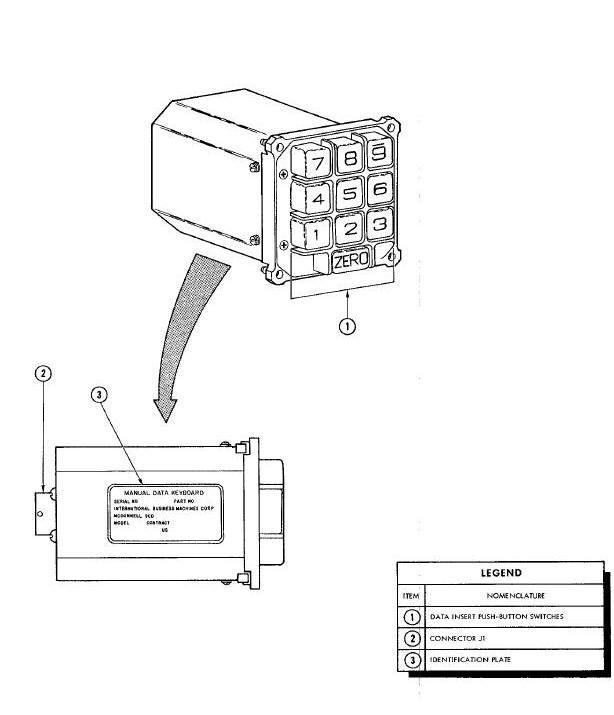
Manual Data Readout Diagram
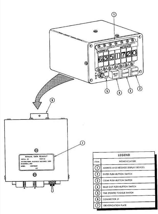
Performance
Data Insertion
Before data is set up for insertion into the computer, all existing data is cleared from the MDIU by pressing the CLEAR push-button switch on the MDR. Then the data insert push-button switches on the MDIU are used to set up a 7-digit decimal number. The first two digits from the left specify the address of the computer memory location in which the data is to be stored, and the last five digits specify the data itself. As the data is set up, it is automatically supplied to the computer accumulator. A digit-by-digit verification of
the address and data is made by means of the ADDRESS and MESSAGE display devices on the MDR. After verification, the ENTER push-button switch on the MDR is pressed to store the data in the selected memory location.
Data Readout
Before data is read from the computer, all existing data is cleared from the MDIU by pressing the CLEAR push-button switch. Then the data insert push-button switches are used to set up a 2-digit decimal number. The two digits specify the address of the computer memory location from which data is to be read. A digit-by-digit verification of the address is made by means of the ADDRESS display devices. After verification, the READ OUT push-button switch on the MDR is pressed and the data is read from the Selected memory location and displayed by the MESSAGE display devices.
MDK Physical Description
The MDK is 3.38 inches wide, and 5.51 inches deep. It weighs 1.36 pounds. External views of the MDK are shown on Figure Above. The major external characteristics are summarized in the accompanying legend.
MDR Physical Description
The MDR is 3.26 inches high, 5.01 inches wide, and 6.41 inches deep. It weighs 3.15 pounds. External views of the MDR are shown on Figure Above. The major external characteristics are summarized in the accompanying legend.
Controls and Indicators
The controls and indicators located on the MDK and MDR are illustrated on Figure below. The accompanying legend identifies the controls and indicators, and describes their purposes.
Manual Data Insertion Unit Front Panels Diagram
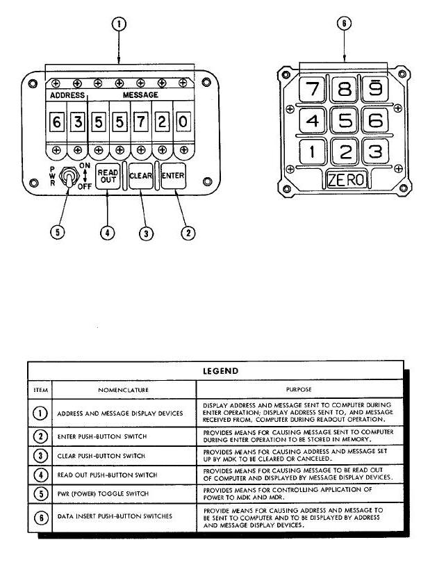
SYSTEM OPERATION
Power
The MDIU receives all of the power required for its operation from the computer. This power consists of the following regulated dc voltages :
(a) +25 vdc and common return
(b) -25 vdc and common return
(c) +8 vac and return
This power is available at the MDIU whenever the computer is turned on. However, it is not actually applied to the MDIU circuits until, the PWR switch on the MDR is turned on. When power is turned on at the MDR, the regulated dc voltages are filtered by a capacitor network and supplied to the MDK and MIR circuits.
MDK Flow(Figure Below)
The MDK has ten data insert push-button switches. These switches are used to select the address of a computer memory location in Which data is to be stored or from which data is to be read. For storing data, the push-button switches are numbered decimally, the insert button encoder is used to convert their outputs to binary coded decimal values that can be used by the computer. These values, called the insert data signals, are supplied Ito the insert serialize in the computer. The insert button encooer also develops the data available signal which is supplied to the discrete input logic of the computer.
Manual Data Keyboard Data Flow
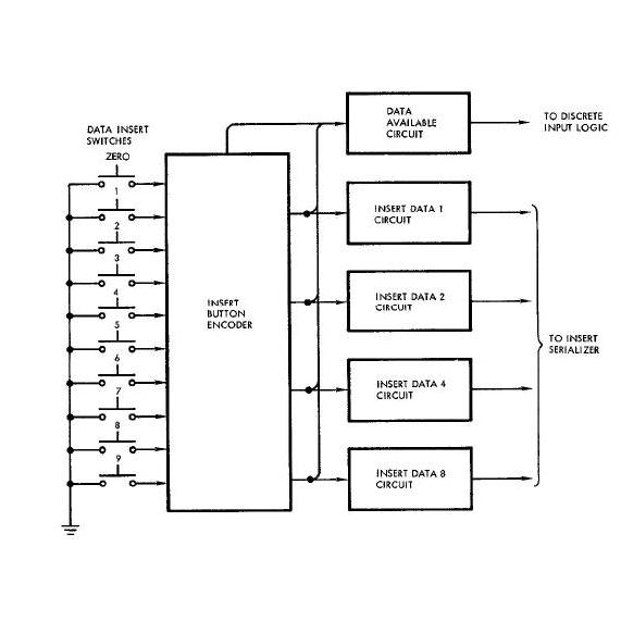
MDR Data Flow (Figure Below)
The MDR has seven digital display devices and three Command push-button switches. The display devices are used to display the address Set up by the data insert push-button switches on the MDK, and to display either the data set up by the data insert push-button switches or the data read from a computer memory location. The command push-button switches, called ENTER, READ OUT, and CLEAR, are used to determine whether data is entered into or read out of the computer, or whether the data that has been set up is to be cleared (or canceled). These push-button switches all supply inputs to the discrete input logic of the computer. Since the display devices provide a decimal display, the binary coded decimal values received from the computer must be decoded before they can be displayed. These values from the computer are supplied to three device select control circuits and three insert data circuits. Another signal from the computer is supplied to the display device drive control circuit. A combination of outputs from the device select control circuits is used in conjunction with the outputs of the display device drive control circuit to select a particular display device. This selection is accomplished by means of the device selector. A combination of outputs from the insert data circuits is used in conjunction with the outputs of the display device drive control circuit to select a particular number on the selected display device. This selection is accomplished by means of the number selector. Thus, through the combined operations of the device selector and the number selector, the binary coded decimal values received from the computer are decoded and an equivalent decimal display is presented on the display devices.
Manual Data Readout Data Flow Diagram
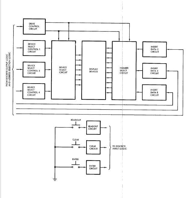
Manual Data Subroutine
The manual data subroutine, which determines when data is transferred between the MDIU and the computer, is described under the Operational Program heading in the DIGITAL COMPUTER SYSTEM OPERATION part of this section.
Interfaces
The MDIU interfaces, all of which are made with the computer, are described under the Interfaces heading in the DIGITAL COMPTER SYSTEM OPERATION part of this section.
AUXILIARY TAPE MEMORY
SYSTEM DESCRIPTION
General
The Auxiliary Tape Memory (ATM) is a self-contained magnetic tape recording system. It is used in spacecraft eight through twelve to provide additional program storage for the digital computer. It has a total storage capacity of over 85,000 thirteen-bit words. This is about seven times that of the computer core memory. The ATM is mounted on a cold plate in the adapter section of the spacecraft (Figure Above).
Physical Characteristics
The ATM is 10 inches x 10 inches x 7 inches and weighs 25.7 pounds (Figure below). It has three external connectors for its interfaces with the digital computer and the Pilots' Display and Control Panel (PCDP). The ATM is hermetically sealed with initial pressurization of one atmosphere, gage, at ambient room temperature and pressure.
Auxiliary Tape Memory Diagram
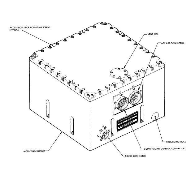
Internally, the ATM contains a tape transport, a drive motor, and the necessary electronics for the read, write and control functions
Functional Characteristics
The functional characteristics of the ATM are summarized as follows:
| Tape length |
525 feet |
| Tape type |
3M type m-1353, Heavy-duty high
resolution, Instrumentation tape |
| Tape speed |
Read/write - 1.5 ips +.0.5, Wind/rewind
- 8 times r/w speed |
| Channels |
16 (9 data, 3 parity, 3 clock, spare) |
| Storage capacity |
Total 12.5x 106 bits (15 channels)
Effective 90,000 13-bit computer words |
| Storage density |
133 bits/inch/channel |
| Data transfer rate |
600 bits/second |
| Ready time-per max program |
10 minutes (verify 3 syllables), 7
minutes (reprogram 2 syllables) |
| Total Read Time |
67 minutes |
| Total wind/rewind time |
10 minutes max. |
| Voltage |
21 - 30 vdc |
| Voltage interrupts | 115 milliseconds |
Controls and Indicators
The controls and indicators associated with the ATM are summarized as follows:
(a) AUX TAPE OFF - ON/RESET - A toggle switch on the PCDP, used to apply power to the ATM or to reset it.
(b) AUX TAPE mode selector - A five - position rotary switch used to select an operational control mode for the ATM. The five
modes are: (1) STDBY, (2) AUTO, (3)WIND (4) REWIND and (5) PROG (reprogram)
(c) Manual Data Insertion Unit (MDIU) - Used to select one of three ATM operational sequences stored in the computer memory. These are: (1) reprogram, (2) verify, and (3) reprogram/verify.
(d) Incremental Velocity Indicator (M) - Display tape position words (on the IVI LEFT/RIGHT channel) and module words (on the
IVI FORE/AFT channel) during the ATM search operation.
(e) AUX TAPE RUN indicator - A lamp on the PCDP which illuminates whenever ATM motor power is applied.
(f) AUX TAPE ERROR indicator - A lamp on the PCDP which illuminates when incorrect frame parity is detected by the ATM.
SYSTEM OPERATION
General
The ATM is used to store operational program modules for in-flight loading of the spacecraft digital computer. It is capable of replacing the majority of the data in syllables zero and one of the computer memory (approx 8,000 thirteen-bit words) in approximately seven minutes.
The program data is stored in the ATM by recording it on magnetic recording tape. Normally, this data is supplied by the Aerospace Ground Equipment (AGE) and recorded (written) on the tape prior to launch time. It is also possible, however, to write data onto the tape using the MDIU and digital computer.
There are two methods of loading the computer memory from the ATM. The first is the auto mode and is considered to be the primary one. The second is the manual mode and is provided as a hack-up method for loading the computer memory. The basic difference between the two is that the auto mode requires fewer manual operations.
Tape Transport
The ATM employs a reel-to-reel peripheral drive transport assembly and a single combination read/write head having 16 tracks with two windings per track. The drive motor accomplishes speed reversal by using a solid-state switch to switch the phase of one winding with respect to the other. A tape speed of 1.5 ips (nominal) is provided for both read and write modes of operation. High speed
wind/rewind operation is accomplished by supplying the drive motor with a frequency and voltage which are eight times those used for the read/write speed. The drive system power is provided by a dc-to-dc inverter and a fixed frequency oscillator. The oscillator output provides the frequency for high-speed operation. The frequency for the read/write speed originates from this same source hut it is reduced by 8:1 through a binary chain.
Write Electronics
Figure below shows the ATM write electronics. The ATM input accepts four-bit (Non-Return-to-Zero) data in serial form (one his in each four-bit frame is a parity bit) together with shift pulses and frame synchronizing clock pulses. The recording circuits convert the serial input into parallel form and record the four-bit frames in parallet NRZ format on the magnetic tape. Each four-bit frame plus a frame synchronizing clock pulse is recorded redundantly on the magnetic tape by triple redundant head drivers. Each data bit is spread across the tape width to minimize errors introduced by tape flaws or foreign matter on the tape surface.
ATM Write Electronics Block Diagram
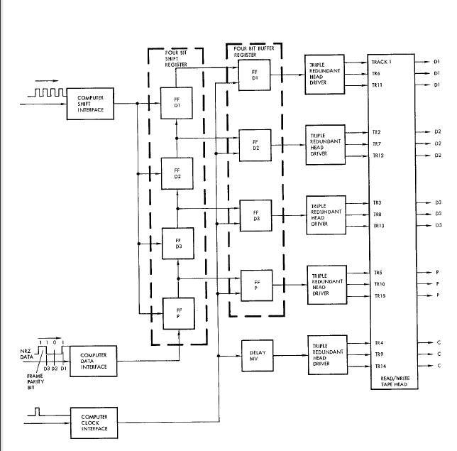
Read Electronics
The play-back (read) electronics (Figure below) uses the same tape head as the write electronics. Each data channel is read by a play-hack amplifier/level detector, and each redundantly recorded data bit (D1, D2, D 3, P, C) is majority voted on (2 out of 3 majority vote) by the ATM voting logic. Three voted outputs (D1, D2, and D3) and clock voters are supplied to output interface amplifiers and, subsequently, to the digital computer (the parity bit is not supplied to the computer). Each data voter output is also supplied to a parity generator. The output of the parity generator is then compared with the voted on parity bit read from the tape. If the recorded parity bit differs from the generated parity bit, the ATM issues an ATM error discrete which will illuminate the AUX TAPE ERROR lamp on the PCDP. A check for tape errors is also performed during the wind and rewind modes of operation by comparing the recorded parity bits with those developed from the voted data bits during playback.
ATM Read Electronics Block Diagram
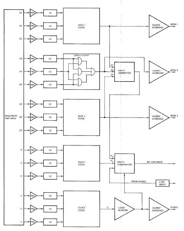
INTERFACES
The ATM interfaces with the digital computer and the PCDP are described in the DIGITAL COMPUTER INTERFACES part of this section.
INCREMENTAL VELOCITY INDICATOR
SYSTEM DESCRIPTION
Purpose
The primary purpose of the Incremental Velocity Indicator (Figure below), herein after referred to as the IVI, is to provide visual indications of incremental velocity for the longitudinal(forward-aft), lateral (left-rlght), and vertical (up-down) axes of the spacecraft. These indicated incremental velocities represent the amount and direction of additional velocity or thrust necessary to achieve correct orbit, and thus are added to the existing spacecraft velocities by means of the maneuver thrusters.
Incremental Velocity Indicator Diagram
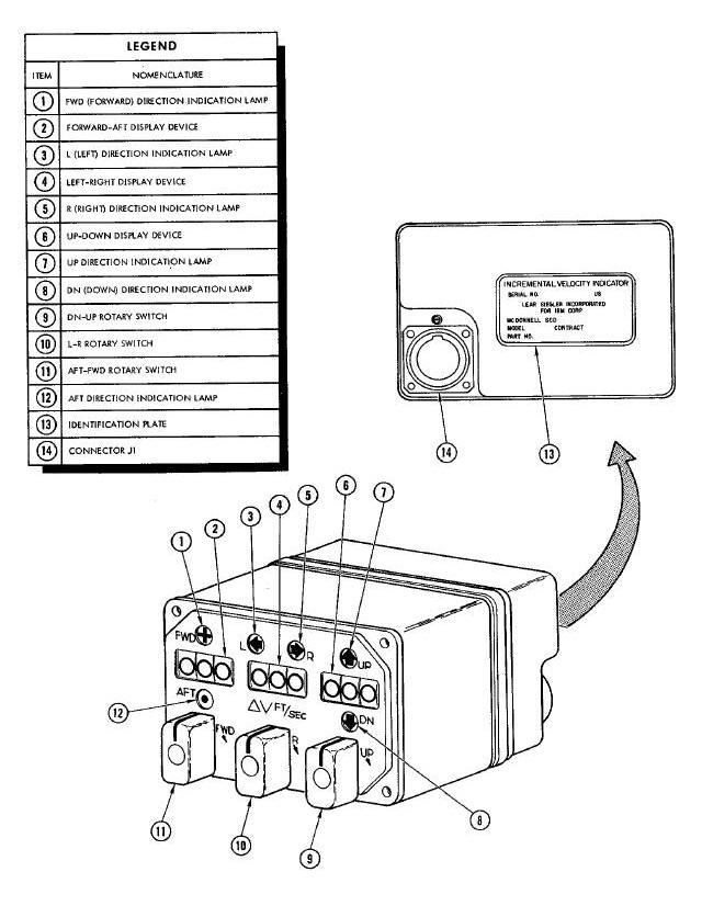
An additional use of the IVI is to display the tape position words and module words from the Auxiliary Tape Memory during its operation. Additional information concerning this usage can be found in the AUXILIARY TAPE MEMORY SYSTEM OPERATION part of this section.
Performance
A three-digit decimal display device and two direction indication 1.mps are used to display incremental velocity for each of the three spacecraft axes. Both the lamps and the display devices can be set up ieither manually by rotary switches on the IVI or automatically by inputs from the computer. Then, as the maneuver thrusters correct the spacecraft velocities, pulses are received from the computer which drive the display devices toward Zero. If a display device is driven beyond zero, indicating an overcorrection of the spacecraft velocity for the respective axis, the opposite direction indication lamp lights and the display device indication increases in magnitude to show a velocity error in the opposite direction.
Physical Description
The IVI is 3.25 inches high, 5.05 inches wide, and 5.99 inches deep. It weighs B.25 pounds. The major external characteristics are shown in Figure above and summarized in the accompanying legend.
Controls and Indicators
The controls and indicators located on the IVI are illustrated on Figure below. The accompanying legend identifies the controls and indicators, and describes their purposes.
Incremental Velocity Indicator Front Panel Diagram
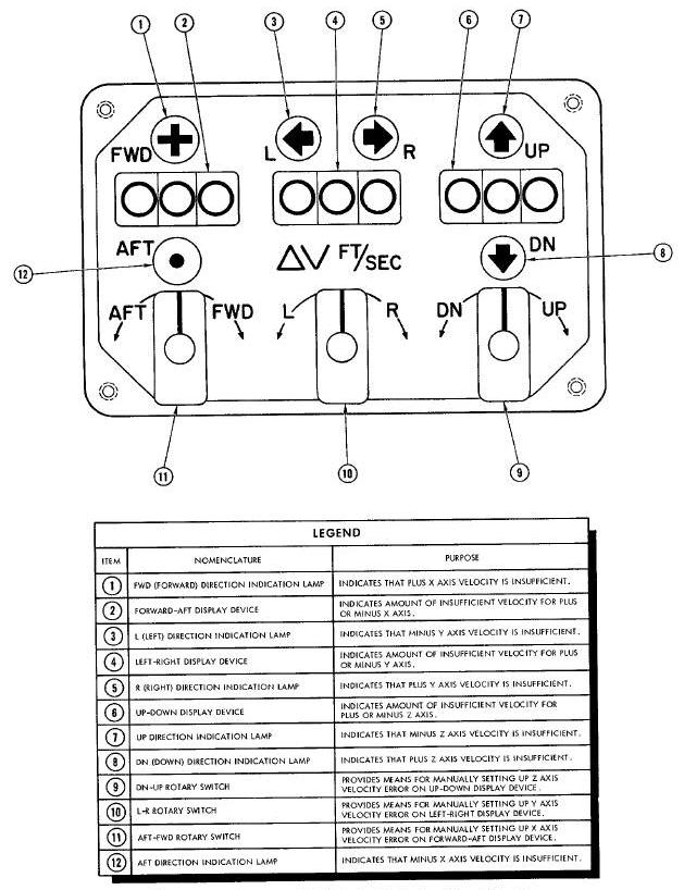
Power
The power required for operation of the IVI is supplied by the IGS Power Supply whenever the computer is turned on. The powered inputs are as follows :
(a) +27.2 vde and return
(b) +5 vdc and return
During the first 3O seconds (or less) following the application of power, the incremental velocity counters on the IVI are automatihally driven to zero. Thereafter, the IVI is capable of normal operation.
Basic Operation
The IVI includes three identical channels, each of which accepts velocity error pulses for one of the spacecraft axes and processes them for use by a decimal display device and its two associated direction indication lamps. The velocity error pulses are either received from the computer or generated within the IVI as determined by the position of the rotary switch aslsociated with each channel. With the spring-loaded switches in their neutral center positions, the IVI processes only the pulses received from the computer. However, rotation of the switches in either direction removes the pulses received from the computer and replaces them with pulses generated by an internal variable oscillator These pulses are generated at a rate of one pulse per second for every 13.5 degrees of rotation until the rate reaches 10 pulses per second. Rotation of the switches beyond the 10 pulse per second position removes the pulses generated by the variable oscillator and replaces them with pulses generated by an internal fixed oscillator. These pulses are generated at a rate of 50 pulses per second. Rotation of the switches beyond the 50 pulses per second position is limited by mechanical stops.
The first pulse received on any channel, from either the computer or one of the oscillators, causes the appropriate display device to display a count of one. Simultaneously, this same pulse causes one of the two associated direction indication lamps to light If the pulse was received on a positive input line, a forward, right, or down direction is indicated, depending on which channel (X, Y, or Z) received the pulse; and if the pulse was received on a negative input line, an aft, left, or up direction is indicated, depending on which channel received the pulse. Each additional pulse either increases or decreases the count depending on the relationship between the sign Of the existing value on the counters and the sign of the added pulse as determine( by the line on which it is received. A pulse having the same sign as the existing error increases the count; conversely, a pulse having the opposite sign of the existing error decreases the count. A series of pulses having the opposite sign indicates a corrective thrusting and eventually reduces the indicated error to zero. An overcorrection, causing still more pulses, causes the count to increase again but with the opposite
direction indication lamp lit.
Incremental Velocity Indicator Data Flow
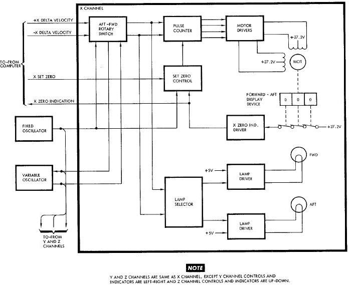
Zero Indication
As shown on Figure below, three series-connected switches are operated by the forward-aft display device. (The same thing is true for the Y and Z channels; however, since the three channels are identical, only the X channel is shown. ) When the display device indicates 000, all three switches are closed. A +27.2 vdc signal is then applied to the X zero indication driver which develops the X zero indication signal that is supplied to the computer. This signal indicates that the respective counter is at zero.
Pulse Count
Velocity error pulses are applied to the lamp selector and the pulse counter via the AFT-FWD rotary switch. If the switch is in the center position, these pulses are received from the computer on the +X delta velocity line and the -X delta velocity line. If the switch is not in the center position, the pulses are received from either the fixed oscillator or the variable oscillator. As previously explained 3 the oscillator that is used depends on the exact position of the switch. Regardless of the source of the pulses, the lamp selector and
the pulse counter operate the same. The lamp selector determines, by means of the sign of the error, which lamp should be lit. Power is then supplied to the selected lamp via the associated lamp driver. Meanwhile, the same pulses are being processed by the pulse counter and supplied to the motor drivers. The pulse counter and the motor drivers operate in a manner that causes the motor to be driven 90 degrees for each pulse that is counted. The direction in which the motor is driven is determined by the relationship between the sign of the existing velocity error count and the sign of the added velocity error pulse. The motor drives the display device so that it changes by a count of one for each 90 degrees of motor rotatlon. Thus the display device maintains an up-to-date count of the size of the velocity error for the assocleted axis (in this case the X axis), and the direction indication maintain an up-to-date indication of the direction of the error.
Zero Command
The IVI counters can be individually driven to zero by means of set zero signals (X set zero, on Figure 8-53) supplied by the discrete output logic of the computer. The set zero signal is supplied to the set zero control circuit which gates the 50 pps output from the fixed oscillator into the pulse counter, provided the display device counter is not already at zero. The pulses from the fixed oscillator then drive the motor in the normal manner until the counter is zeroed. The pulses are applied in such a manner that the count always
decreases, regardless of the initial value.
Interfaces
The IVI interfaces, which are made with the computer and the IGS Power Supply, are described under the Interfaces heading in the DIGITAL COMPUTER SYSTEM OPERATION part of this section.
Acronyms
A
ACE - Attitude Control Electronics (ACE)
ACME - Attitude Control and Maneuver Electronics (ACME)
ACPU - Auxiliary Computer Power Unit (ACPU)
ADG - Attitude Display Group (ADG)
ATM - Auxiliary Tape Memory (ATM)
ATDA - Augmented Target Docking Adapter (ATDA)
B
BEF - Blunt End Forward (BEF)
BCD - Binary Coded decimal (BCD)
C
CLA - clear and add
CLD - (clear and add discrete)
D
Digital Command System (DCS)
F
Flight Director Indicator (FDI)
I
IGS - Inertial Guidance System (IGS)
IMU - Inertial Measurement Unit (IMU)
IVI - Incremental Velocity Indicator (IVI)
L
LC - Logical Choice (LC)
M
MDK - Manual Data Keyboard (MDK)
MDR - Manual Data Readout (MDR)
MIDU - Manual Data Insertion Unit (MDIU)
MPY - (multiply)
O
OAME - Orbit Attitude and Maneuver Electronics (OAME)
OAMS - Orbit Attitude Maneuver System (OAMS)
P
PAST - Phase Angle Shift Technique (PAST)
PCDP - Pilots' Display and Control Panel (PCDP)
PRO - (process input or output)
R
RCS - Re-entry Control System (RCS)
REP - Rendezvous Evaluation Pod (REP)
RSU - (reverse subtract)
S
SEF - (Small End Forward)
SHF - (shift)
SPQ - (store product or quotient)
SSECO - Second Stage Engine Cut-0ff (SSECO)
STO - (store)
SUB - (subtract)
T
TMI - (transfer on minus accumulator sign)
TNZ - (transfer on non-zero)
TRA - (transfer)
TRS - Time Reference System (TRS)