PYROTECHNICS and RETRO ROCKET SYSTEM
Cartridge Diagram (Gas Pressure)
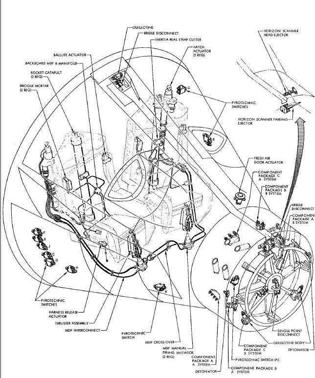
SEPARATION ASSEMBLIES and DEVICES
Spacecraft Pyrotechnic Devices Diagram (R & R Section)
SPACECRAFT/LAUNCH VEHICLE SEPARATION ASSEMBLY
Spacecraft/Launch Vehicle Separation Assembly Diagram
EQUIPMENT SECTION/RETROGRADE SECTION SEPARATION ASSEMBLY
Separation Assembly-Equipment Section/Retrograde Section
RETROGRADE SECTION/RE-ENTRY MODULE SEPARATION ASSEMBLY
Retrograde Section/Re-Entry Module Separation Assembly Diagram
RENDEZVOUS AND RECOVERY SECTION SEPARATION ASSEMBLY
Rendezvous and Recovery Section Separation Assembly Diagram
Wire Bundle Guillotine Diagram
WIRE BUNDLE GUILLOTINE (CABLE CUTTING)
Wire Bundle Guillotine Diagram (Cable Cutting)
HORIZON SCANNER FAIRING RELEASE ASSEMBLY
Horizon Scanner Fairing Release Assembly Diagram
HORIZON SCANNER RELEASE ASSEMBLY
Horizon Scanner Release Assembly
Fresh Air Door Actuator Diagram
Nose Fairing Ejector Assembly Diagram
Egress System and Devices Diagram
HATCH ACTUATOR INITIATION SYSTEM (MDF)
Hatch Actuator Initiation System Diagram
Hatch Actuator Assembly Diagram
Seat Ejector - Rocket/Catapult Diagram
THRUSTER ASSEMBLY-SEAT/MAN SEPARATOR
Harness Release Actuator Assembly Diagram
BALLUTE DEPLOY AND RELEASE SYSTEM
Ballute Deploy and Release System Diagram
DROGUE MORTAR-BACKBOARD JETTISON ASSEMBLY
Backboard Jettison Assembly Diagram
PARACHUTE LANDING SYSTEM PYROTECHNICS
Parachute Landing System Pyrotechnics Diagram
DROGUE PARACHUTE MORTAR ASSEMBLY
Pilot Parachute Mortar Assembly Diagram
DROGUE PARACHUTE REEFING CUTTERS
DROGUE PARACHUTE BRIDLE RELEASE GUILLOTINES
PILOT PARACHUTE MORTAR ASSEMBLY
PILOT PARACHUTE REEFING CUTTERS
Pilot Parachute Reefing Cutters Diagram
PILOT PARACHUTE APEX LINE GUILLOTINE
Pilot Parachute Apex Line Guillotine Diagram
Main Parachute Disconnects Diagram
Retrograde Rocket System Diagram
RETROGRADE ROCKET MOTOR ASSEMBLY
Retrograde Rocket Motor Assembly Diagram
RETROGRADE ROCKET IGNITER ASSEMBLY
Retrograde Rocket Igniter Assembly Diagram
DOCKING SYSTEM PYROTECHNIC DEVICES
EMERGENCY DOCKING RELEASE SYSTEM
Emergency Docking Release System Diagram
FUEL CELL HYDROGEN TANK VENT ACTUATOR
H 2 Tank Vent Actuator Assembly Diagram
The pyrotechnic devices and retrograde rockets, installed in the Gemini Spacecraft, provide the escape system propulsion modes, enable and disable systems, and separate various sections and assemblies. Pyrotechnics are installed in each of the major sections and in numerous locations throughout the spacecraft. The retrograde rockets retard the spacecraft'sorbital velocity to initiate re-entry into the earths atmosphere. The retrograde rockets are located in the retrograde section of the adapter.orbital velocity to initiate re-entry into the earths atmosphere. The retrograde rockets are located in the retrograde section of the adapter.
RECURRENT COMPONENTSRECURRENT COMPONENTS
Some pyrotechnic items are used extensively throughout the spacecraft. To avoid repetition in subsequent paragraphs, their description and operation will be presented at this time. When describing the various systems, these components shall be mentioned by name only.
The typical detonator (Figure Diagram) is a machined steel or aluminum cylinder containing an ignition mix, booster charge and an output charge. In some instances a pyrotechnic time delay column is used to provide a time delay between ignition and detonation. The case is threaded at one end for installation purposes. An electrical receptacle is provided at the other end. Electrically, the detonators are provided in two different configurations. One incorporates two independent, identical firing circuits. The other incorporates only one firing circuit. The circuits of both detonators are electrically insulated from and independent of the detonator body. Each firing circuit consists of two electrical connector pins, across which a bridge wire is incorporated. The detonator is used to initiate high explosive components.
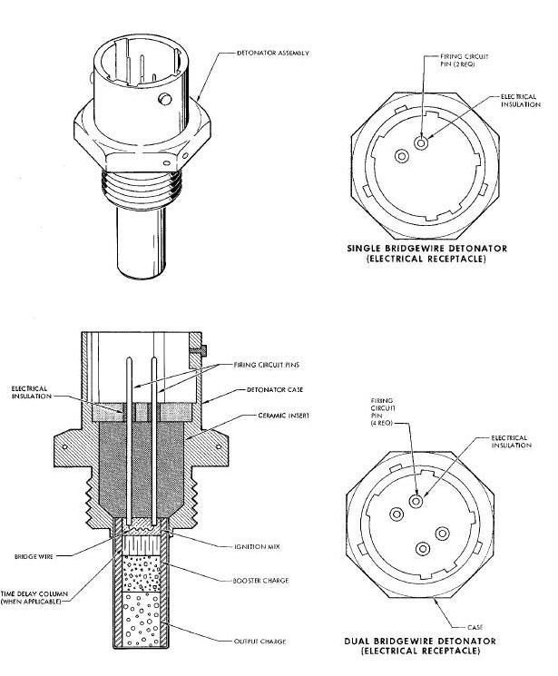
Upon receipt of a 28 vdc electrical signal, the firing circuit or circuits will cause the detonator to fire. Either circuit (detonators with dual circuits) will initiate the charge with the same performance characteristics as exist when both circuits are operative. The bridge wire ignites the ignition mix which in turn ignites the booster charge. The booster charge then propagates detonation to the output charge. If a delay column is installed, the ignition mix will ignite the delay column which ignites the booster charge. The output charge detonates and transmits the detonation wave to the assembly to which it is attached.
The typical cartridge (Figure Below) is a machined steel cylinder containing an ignition mix and an output charge. In some instances a pyrotechnic time delay column is used to provide a specific time delay between ignition and output. The cartridge is threaded at one end for installation purposes. An electrical receptacle is provided at the opposite end. Electrically, the cartridges are provided in two different configurations. One incorporates two independent, identical firing circuits. The other incorporates only firing circuit. The circuits of both cartridges are electrically insulated from and independent of the cartridge body. Each firing circuit consists of two electrical connector pins mounted in a high strength ceramic dielectric base and with a bridge wire connected between the two pins. The cartridge output is a hot gas pressure.
Cartridge Diagram (Gas Pressure)
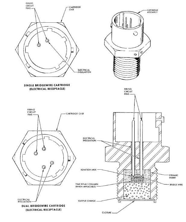
When initiated by a 28 vdc electrical signal, the firing circuits will cause the cartridge to function. Either circuit (cartridges with dual circuits) will fire the charge with the same performance characteristics as exist when both circuits are operative. The bridge wire ignites the ignition mix which propagates burning to the delay column if applicable, and to the output charge. The output charge produces gas pressure that is used to operate the specific device in which the cartridge is installed.
Flexible Linear Shaped Charge (FLSC) is a V-shaped, flexible lead sheathing containing a high explosive core. FLSC is used in separation assemblies to sever various types, thicknesses, and shapes of materials. The specific type, shape and thickness of the material to be separation, dictates the amount of explosive contained in the FLSC. In the Gemini Spacecraft and Agena Adapter, the FLSC is provided in four different core loadings: 7, 10, 20, and 25 grains per foot.
When installed, the open portion of the V-shaped FLSC is placed towards the item to be severed. The FLSC is detonated by a booster charge that has been initiated by a detonator. The explosive core of the FLSC detonates, resulting in collapse of the sheathing in the V groove, which produces a cutting jet composed of explosive products and minute metal particles. This Jet produces extremely high localized pressures resulting in stress far above the yield strength of the target material.
Mild Detonating Fuse (MDF) is a strand of high explosive encased in a lead sheathing with s circular cross section. MDF is used as a separation device and as an explosive interconnect. As a separation device, the strand contains 5 grains of explosive per foot. As an explosive interconnect, the strand contains 2 or 3.3 grains of explosive per foot. The interconnect type MDF is installed in either flexible woven steel mesh or nylon hose and rigid stainless steel tubing. Both rigid and flexible MDF have a small booster charge incorporated at each end. The booster charges are referred to as acceptor and donor. The acceptor being on the end that receives a detonation wave from an initiator. The donor being on the end that transmits a detonation wave to a component or other acceptor. The interconnects are attached to various devices by AN type or Bendix type electrical Connectors.
The MDF used as a separation device is placed in a groove milled in a magnesium ring. The ring is formed to the shape of the items to be separated and is placed between the mating surfaces. The assembly to be Jettisoned is attached to the main structure by frangible bolts. The bolts have been axially drilled to reduce tensile strength to a specified breaking point. When detonated, the MDF exerts a force against the mating surfaces greater than the tensile strength of the frangible bolts. The MDF, used as an explosive interconnect, is initiated when a detonator or booster charge propagates a detonation wave to the MDF booster. The booster strengthens the wave and transmits it linearly through the length of the MDF strand. The booster, at the opposite end, propagates the detonation wave to the device to which it is attached.
SEPARATION ASSEMBLIES and DEVICES
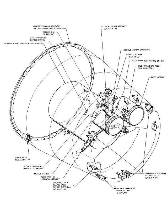
There are several different types of separation assemblies and devices used in the Gemini Spacecraft (Figure Below). These assemblies and devices are presented individually in the following paragraphs.
Spacecraft Pyrotechnic Devices Diagram(R & R Section)

SPACECRAFT/LAUNCH VEHICLE SEPARATION ASSEMBLY
The spacecraft/launch vehicle separation assembly (Figure Below) separates the spacecraft from the launch vehicle by severing the mating ring. The separation assembly primarily consists of two flexible linear shaped charges (FLSC) installed around the periphery of the mating ring, three detonators, three detonator blocks, three dual boosters, a molded backup retainer and a back blast shield. The dual boosters are inserted in the detonator blocks. The dual booster protrude into the molded backup retainer, indexed directly above the FLSC, when the detonator blocks are installed. The detonators are inserted in the detonator blocks with the output charge adjacent to the dual boosters. The back blast shield attaches the molded backup retainer and FLSC to the mating ring.
Spacecraft/Launch Vehicle Separation Assembly Diagram
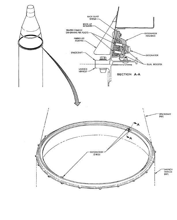
Upon receipt of the 28 vdc electrical signal,
the detonators transmit a detonation wave that is propagated to the dual
boosters. The dual boosters strengthen the detonation wave to achieve
proper detonation of the FLSC. The FLSC detonates and severs the mating
ring redundantly. The backup retainer absorbs the shock in the back
blast. The back blast shield protects the structure and equipment from
shrapnel. Proper detonation of only one strand of FLSC is sufficient to
sever the mating ring.
EQUIPMENT SECTION/RETROGRADE SECTION SEPARATION ASSEMBLY
The equipment section/retrograde section separation assembly (Figure Below) separates the equipment section of the adapter from the retrograde section of the adapter. The assembly basically consists of two main units: the shaped charge assembly and the tubing cutter assembly. The shaped charge assembly primarily consists of two flexible linear shaped charges (FLSC), three detonator blocks, containing three crossovers and six boosters, three detonators, ten segmented back-up strips and a molded backup retainer. The detonator blocks provide for installation of the detonators. One detonator block provides for the installation of the tubing cutter explosive interconnect. The tubing cutter assembly primarily consists of an explosive interconnect (MDF), two formed aluminum parallel housings, molded backup retainer, two flexible linear shaped charges with boosters attached, a detonator block and a detonator. The explosive interconnect (MDF) is a flexible nylon hose containing a strand of high explosive and end mounted booster charges. The interconnect has Bendix type connectors incorporated at each end for attaching the interconnect to the cutter and shaped charge detonator blocks. The interconnect is attached to the cutter detonator block with its booster charge adjacent to one of the boosters on the FLSC. The detonator is installed in the cutter detonator block with its output end adjacent to the other booster on the FLSC. The cutter assembly is bracket mounted to the inside of the retrograde section of the adapter, forward of the parting line. The shaped charge assembly is installed around the outer periphery of the adapter at the equipment section and retrograde section parting lin..
Separation Assembly-Equipment Section/Retrograde Section
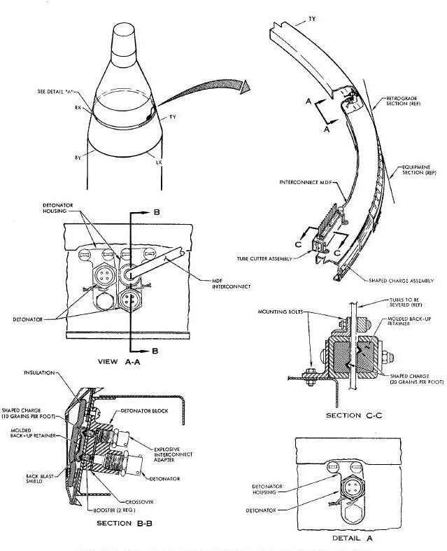
When initiated by a 28 vdc electrical signal, the detonators Mill fire. The detonators of the shaped charge assembly transmit a shock or detonation wave to the crossovers which in turn initiates the boosters. The boosters propagate the wave to the FLSC. The FLSC detonates and functions to sever the adapter at the parting line redundantly. The detonator of the tubing cutter assembly propagates detonation to the booster on one strand of FLSC in the cutter assembly. The explosive interconnect transmits detonation from the shaped charge assembly to the booster on the other strand of FLSC in the cutter assembly. The two boosters propagate the shock wave to the FLSC. The two strands of FI_C in the cutter assembly detonate and sever the twelve aluminum tubes and one nylon tube. Proper detonation of only one strand of FLSC in both the shaped charge assembly and tubing cutter assembly, is sufficient to achieve separation.
RETROGRADE SECTION/RE-ENTRY MODULE SEPARATION ASSEMBLY
The retrograde section/re-entry module separation assembly (Figure Below) functions to separate the retrograde section of the adapter from the re-entry module. Separation is accomplished by severing the three titanium straps and various tubes and wire bundles. The separation assembly primarily consists of three cutter assemblies, three detonator housings, three detonators, three parallel booster columns, six explosive interconnects, and three unions. The detonator housings containa booster column and a parallel booster column. The cutter assemblies consist of two parallel machined aluminum bars that contain four strips of FLSC. The bars are Joined by the detonator housings with the parallel boosters. A detonator is installed in each of the three detonator housings. The cutter assemblies are located in three places around the parting line and are linked by the explosive interconnects.a booster column and a parallel booster column. The cutter assemblies consist of two parallel machined aluminum bars that contain four strips of FLSC. The bars are Joined by the detonator housings with the parallel boosters. A detonator is installed in each of the three detonator housings. The cutter assemblies are located in three places around the parting line and are linked by the explosive interconnects.
Retrograde Section/Re-Entry Module Separation Assembly Diagram

When initiated by a 28 vdc electrical signal, the detonators propagate a detonation or shock wave to the boosters which relay propagation to cutter FLSC and simultaneously the shock wave is propagated to the explosive interconnects. The interconnects transmit the wave to all three cutter assemblies. This is to ensure detonation of all three cutters FLSC, in the event one or even two detonators do not function. Detonation of the cutter FLSC completely severs the titanium straps, wire bundles and tubing redundantly. Proper detonation of only two opposing strips of FLSC in each cutter is sufficient to achieve separation.
RENDEZVOUS AND RECOVERY SECTION SEPARATION ASSEMBLY
The rendezvous and recovery section separation assembly ((Figure Beloww)separates the Rendezvous and Recovery (R & R) section from the Re-entry Control System (RCS) section. The assembly primarily consists of Mild Detonating Fuse (MDF), MDF housing ring, two detonators, two detonator housings and two booster charges. Two strands of MDF are installed in parallel grooves milled in the housing ring face. The grooves intersect at the booster charges which are installed approximately 180 ° apart. The R & R section is attached to the RCS section by frangible bolts, with the MDF ring fastened to the R & R section at the mating surface. The detonator housings are installed in the RCS section, with the detonators indexed directly above the booster charges, when the sections are mated..
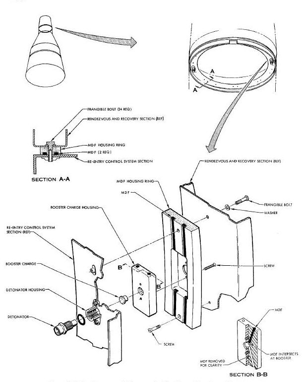
When initiated by a 28 vdc electrical signal, the detonators propagate a detonation wave to the two booster charges. The booster charges strengthen the detonation wave and transmit it to the dual strands of MDF. The MDF detonates, exerting a force against the RCS and R & R section mating surfaces. The force breaks all the frangible bolts and allows the pilot chute to pull the R & R section free of the spacecraft. Satisfactory propagation of either strand of MDF will successfully separate the R & R section.
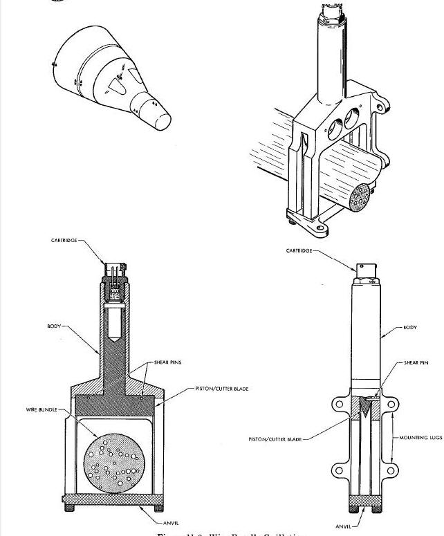
The wire bundle guillotine (Figure Below) is used throughout the spacecraft to sever various sized bundles of electrical wires. The guillotines are used in two sizes. One size can sever a wire bundle up to one and one quarter inches in diameter and the other can sever a wire bundle up to two and one half inches in diameter. Both sizes are similar in design, appearance and operation. The guillotines primarily consist of a body, end cap or anvil, piston/cutter blade, shear pin(s) and an electrically fired gas pressure cartridge. The body houses the piston/cutter blade, provides for installation of the cartridge, and attachment of the anvil. The anvil is removable to facilitate removal and installation of either the guillotine or wire bundle. Two guillotines are used on a wire bundle, one on each side of the separation plane. Lugs, for attaching the guillotine to the spacecraft structure, are an integral part of the guillotine body.
Wire Bundle Guillotine Diagram
WIRE BUNDLE GUILLOTINE (CABLE CUTTING)
The wire bundle guillotine (cable cutting) (Figure Below) is used to sever woven stainless steel cables. The guillotine primarily consists of the body, piston/cutter blade, shear pin, anvil and end cap, and two electrically fired gas pressure cartridges. The body provides a piston actuation area and provides for cartridge installation. The anvil is retained in the barrel section of the body by the end cap. The anvil and end cap is removable to permit guillotine and cable installation and removal. Lugs, for attaching the guillotine to the spacecraft structure, are an integral part of the body. The shear pin is provided to retain the piston/cutter blade in a retracted position.
Wire Bundle Guillotine Diagram (Cable Cutting)
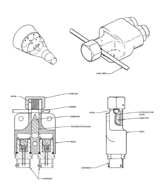
When Initiated by a 28 vdc electrical signal, the two cartridges fire and produce gas pressure. The gas pressure exerts force on the piston/cutter blade. When sufficient force is applied, the piston/cutter blade severs the shear pin. The piston/cutter blade travels the length of the barrel section and severs the cable installed in the guillotine. The cable is then free to pull out of the guillotine.
The tubing cutter/sealer (Figure
Below) is used to cut and seal two stainless steel, Teflon lined
tubes. The tubes contain hypergolic propellants used in the Orbit
Attitude and Maneuvering System (OAMS). Two tubing cutter/sealer
assemblies are located in the adapter, one on each side of the
retrograde/equipment section separation line. The tubing cutter/sealer
assembly primarily consists of the body, anvil, one electrically fired
gas pressure cartridge, four shear pins and cutter assembly. The cutter
assembly consists of the piston, crimper and blade. The crimper and
blade are attached to the piston by two of the shear pins, (sequencing
pins). The piston is secured in the body by the other two shear pins,
(initial lock pins). The body provides for the installation of the
cartridge, attachment
of the anvil, and housing for the cutter assembly. Lugs, for attaching
the tubing cutter/sealer to the spacecraft structure, are an integral
part of the body.
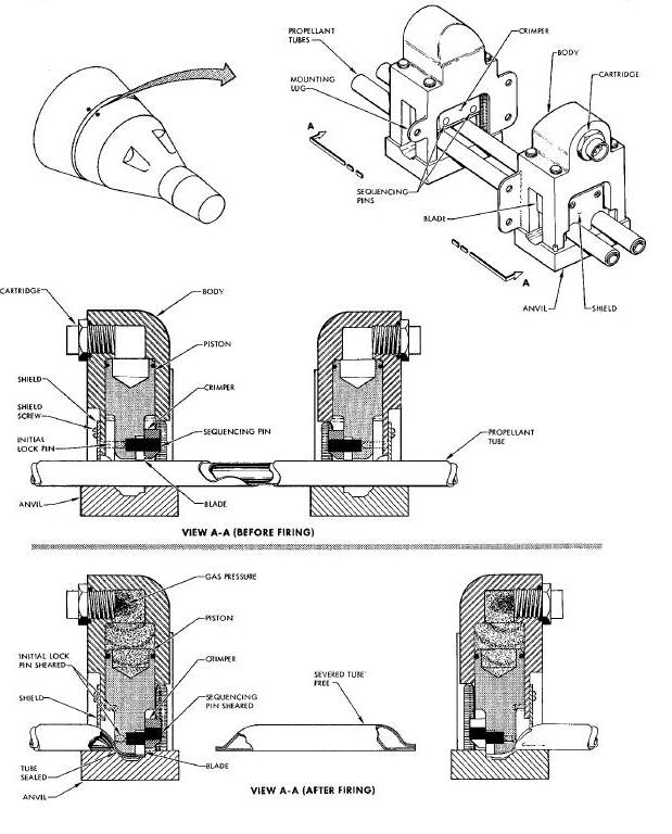
When initiated by a 28 vdc electrical signal, the cartridge fires and generates gas pressure. The gas pressure exerts a force on the piston of the cutter assembly. When sufficient force is applied to the piston, the initial lock pins are severed and the cutter assembly strokes to seal and cut the two tubes. The blade and crimper, extending past the end of the piston, contact the tubing first. As the cutter assembly moves down, the crimper flattens the tubing against the raised portion of the anvil. As the cutter assembly continues its travel, the sequencing pins are severed between the crimper and blade, stopping the travel of the crimper. The base of the piston and blade further crimp and seal the tubing with the blade severing the tubing. The sealed portion of the tubing remains in the tubing cutter/sealers at adapter separation. The severed portion of the tubing between the tubing cutter/sealers is free to pull out at adapter separation.
The pyrotechnic switch (Figure Below) functions to positively open electrical circuits and prevent current flow in various wire bundles prior to their being severed. The switches are located in various places throughout the re-entry module. The switches primarily consist of the body, actuator (piston), shear pin, spring lock, and electrically fired gas pressure cartridge. The shear pin secures the actuator in the switch closed position prior to switch actuation. Incorporated in opposite ends of the switch body are two electrical receptacles. The end mounted receptacles contain hollow spring leaf contacts. The contacts are axially connected by pins mounted in the actuator. All switches are identical in design and operation with the exception of the number of contacts in the receptacles. One model contains 41 contacts, and the other model contains 55 contacts. Lugs, for attaching the switch to the spacecraft structure, are an integral part of the body.
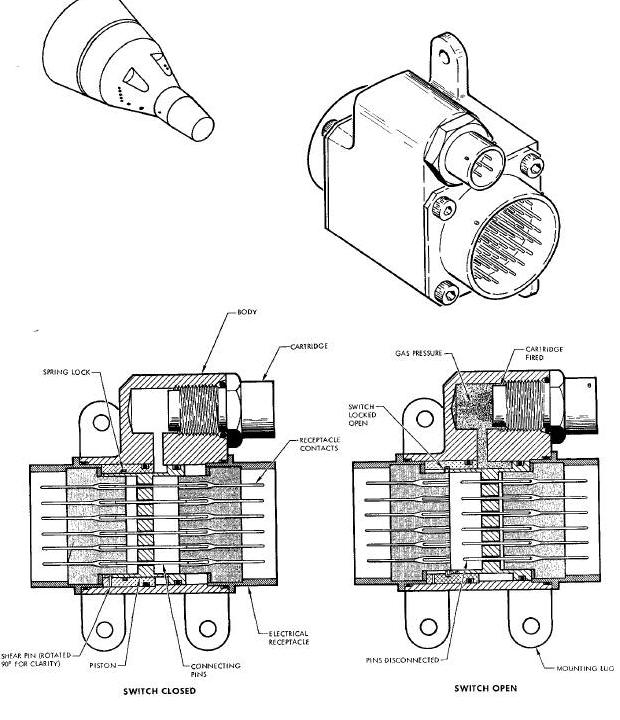
When initiated by a 28 vdcelectrical signal, the cartridge fires and generates gas pressure that is ported through the switch body to the actuator. The pressure exerts a force against a flange of the actuator. The force causes the actuator to sever the shear pin and move axially in the body. As the actuator moves, the connecting pins mounted in the actuator are disengaged from the hollow contacts at one end and are driven further into the hollow contacts at the other end. The spring lock drops into place behind the actuator and prevents it from returning to its original position. The actuator is thus held in the electrically open position..
HORIZON SCANNER FAIRING RELEASE ASSEMBLY
The horizon scanner fairing release assembly (Figure Below) secures the horizon scanner fairing to the spacecraft, and when initiated, Jettisons the fairing. The assembly primarily consists of the actuator housing, actuator, actuator extension, main piston, release piston, eight locking pins and two electrically fired gas pressure cartridges. The actuator extension forms a positive tie between the actuator and the scanner fairing. The actuator is locked to the main piston by four locking pins. The main piston is locked in the base of the actuator housing by four locking pins, that are held in place by the release piston. The release piston is spring energized in the locked position. The actuator housing provides for installation of the cartridges and mounting for the assembly.
Horizon Scanner Fairing Release Assembly Diagram
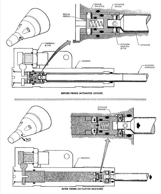
When imitated by a 28vdc electrical signal, the cartridges fire and produce gas pressure. The pressure is ported through a milled passage in the actuator housing, to the base of the piston. The gas pressure moves the release piston forward, which enables the four locking pins to cam inboard, releasing the main piston. The gas pressure causes the main piston, with attached actuator, to move through the length of the actuator housing. As the piston reaches the end of the housing, a shoulder stops the piston travel. The four locking pins, searing the actuator extension to the piston, cam outboard into a recess and release the actuator extension. The actuator extension being thus freed is Jettisoned with the scanner fairing attached.
HORIZON SCANNER RELEASE ASSEMBLY
The horizon scanner release assembly (Figure Below) secures the horizon scanners to the spacecraft and Jettisons the scanners when initiated. The horizon scanner release assembly primarily consists of the actuator housing, actuator, locking mechanism, cartridge housing, and two electrically fired gas pressure cartridges. The actuator is secured in the actuator housing by the locking mechanism. The locking mechanism consists of a tang lock, tang lock retainer and a shear pin. The tang lock is secured to and is located in the base of the actuator housing. The actuator housing is attached to and becomes a part of the spacecraft structure. The scanner base support and mounting platform are attached to the actuator prior to installing the cartridge housing on the actuator. The two cartridges are installed in the cartridge housing.
Horizon Scanner Release Assembly
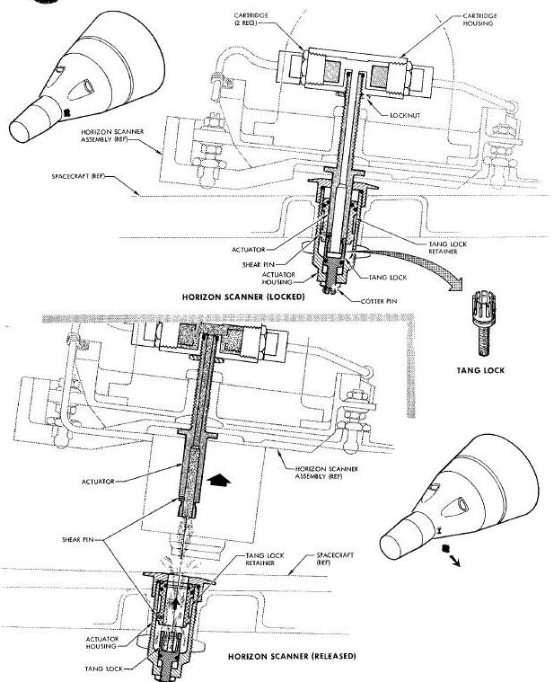
When initiated by a 28 vdc electrical signal, the two cartridges fire and produce gas pressure which is ported through the hollow actuator to the base of the actuator housing. Slots in the tang lock allow the gas pressure to flow to the base of the tang lock retainer. The gas pressure exerts a force against the base of the retainer. The retainer moves axially in the actuator housing, severing the shear pin and exposing the tines of the tang lock. The tines cam open, releasing the actuator and allowing the gas pressure to Jettison the actuator and horizon scanners.
The fresh air door actuator (Figure Below) is provided to retain the fresh air door to the spacecraft and to eject the door when initiated. The fresh air door actuator is located forward of the egress hatches, to the left of the spacecraft centerline and below the outer mold line. The actuator primarily consists of the breech, plunger, screw and two electrically fired gas pressure cartridges. The plunger forms a positive tie between the fresh air door and the breech. The plunger is retained in the breech by the screw which acts as a shear pin. The breech provides for installation of the two cartridges. Lugs, for attaching the actuator to the spacecraft structure, are an integral part of the breech.
Fresh Air Door Actuator Diagram
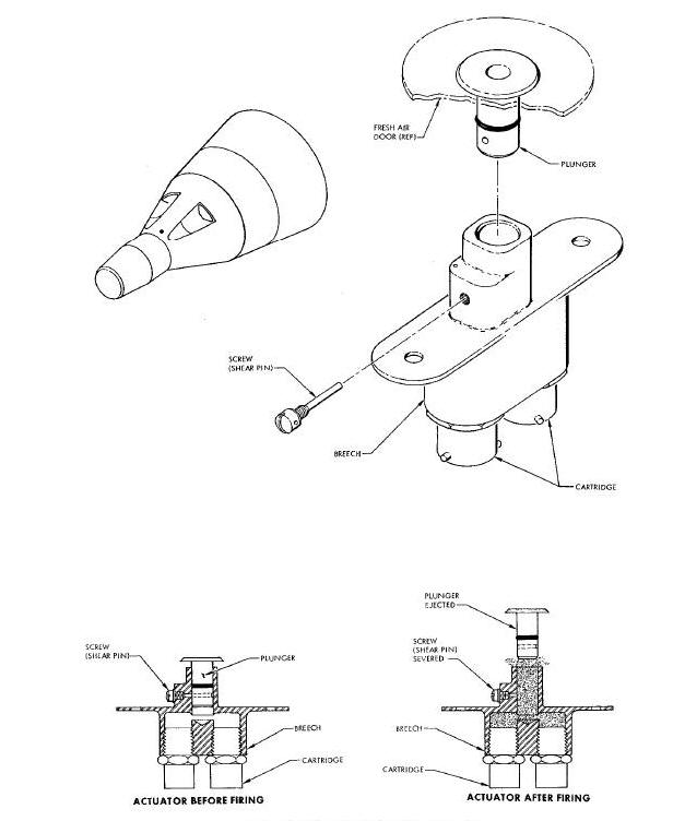
When initiated by a 28 vdc electrical signal, the cartridges are caused to fire and generate gas pressure that exerts a force on the plunger. When sufficient force is applied, the plunger severs the screw and is ejected out of the breech. The plunger and fresh air door are then Jettisoned free of the spacecraft.
The nose fairing ejector (Figure Below) is used to secure the rendezvous and recovery nose fairing to the spacecraft until initiated by a 28 vdc signal. When initiated the pyrotechnic ejector will positively Jettison the nose fairing. The nose fairing ejector assembly consists of a breech, ballistic hose, actuator assembly, crank assembly, and an electrically fired gas pressure cartridge. The nose fairing is attached to the crank assembly. An actuator shaft forms a positive tie between the actuator body and the crank assembly. The actuator shaft is locked to a piston in the actuator by two locking pins and held in place by a shear pin in the end cap of the actuator. The actuator assembly is connected to a breech by a ballistic hose. The breech provides for installation of the cartridges and is positioned approximately nine inches from the actuator. The actuator is installed on the antenna support and fairing actuator fitting of the R and R section and is located on the X axis, five inches from Y zero.
Nose Fairing Ejector Assembly Diagram
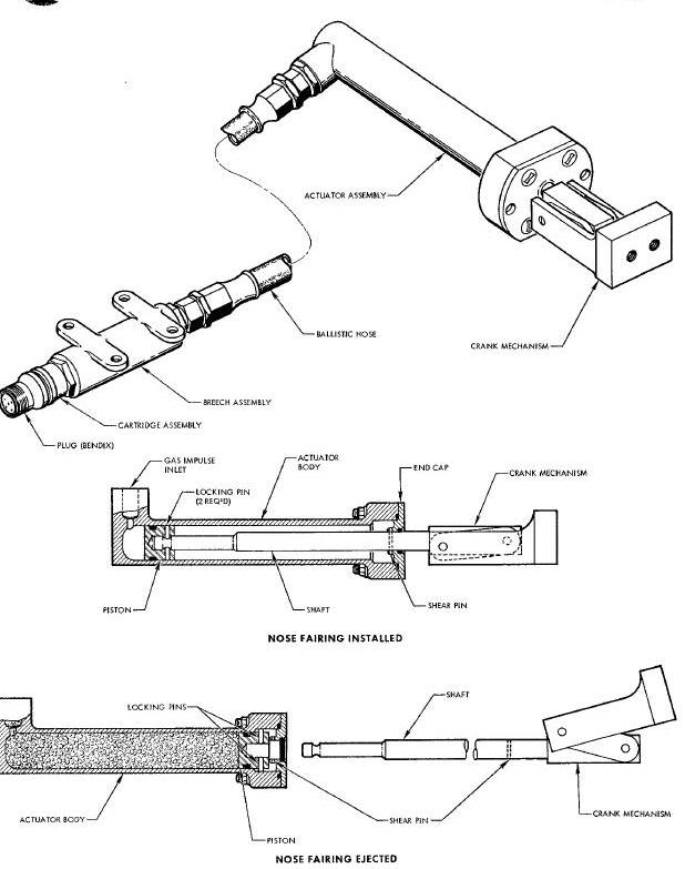
When initiated by a 28 vdc signal, the cartridge generates gas pressure which is transferred through a ballistic hose to the actuator housing and exerts a force on the actuator piston. The gas pressure causes the piston, with attached shaft, to move, severing the shear pin and continuing through the length of the actuator housing. As the piston reaches the end of the housing, the two locking pins, securing the shaft to the piston, cam outboard into a recess and release the actuator shaft: The actuator shaft, now free, is Jettisoned, with the nose fairing attached, by the crank mechanism. The crank mechanism provides an angled Jettisoning of the fairing from the axial movement of the ejector shaft, without recontact with the spacecraft. A hinge on the nose fairing, located on the outer mold line, releases and directs the path of the fairing away from the spacecraft.
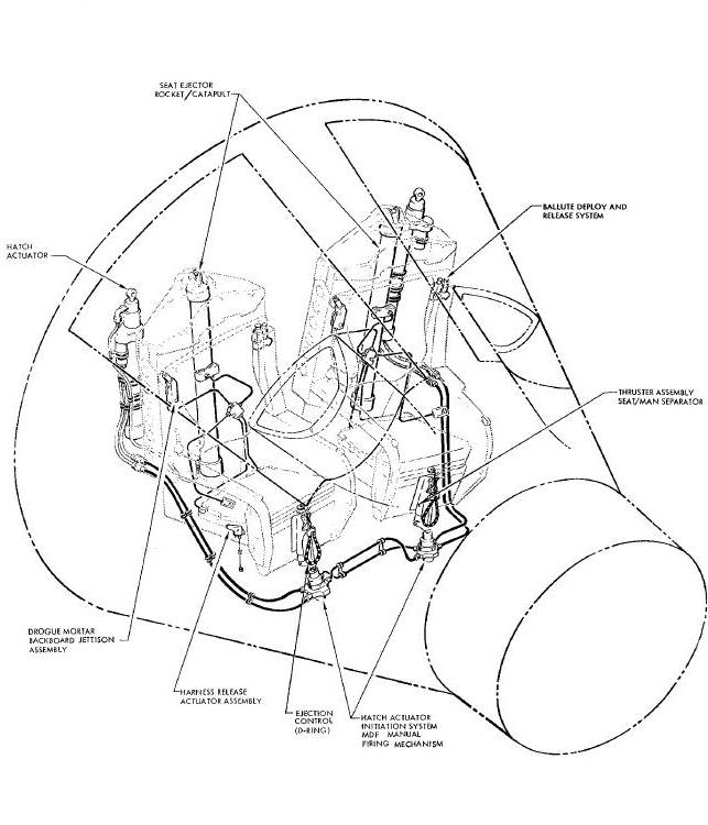
The egress systems and devices (Figure Below) provide the pilots with a rapid and positive method of escaping the spacecraft, should an emergency arise. The system is manually initiated and is used below an altitude of 15,000 feet only. Each system and device is presented in the sequence of their operation
Egress System and Devices Diagram
HATCH ACTUATOR INITIATION SYSTEM (MDF)
The hatch actuator initiation system (Figure Below) is used to initiate the firing mechanisms of both hatch actuators. The system is manually activated by either pilot. The system primarily consists of 8 MDF interconnects, two MDF crossovers and two manual firing mechanisms. The interconnects consists of four rigid and four flexible MDF assemblies that connect the firing mechanisms to the hatch actuators. The two crossovers are rigid MDF assemblies that cross connect the two initiation system firing mechanisms. The firing mechanisms each contain dual firing pins, dual percussion primers, and a booster charge. The firing mechanism is drilled and tapped for installing two MDF interconnects and two crossovers. The MDF interconnects and crossovers are installed so that the small booster on the end of each MDF is adjacent to the booster charge of the firing mechanism. The firing mechanism is attached to the spacecraft structure, located below the pilots feet.
Hatch Actuator Initiation System Diagram
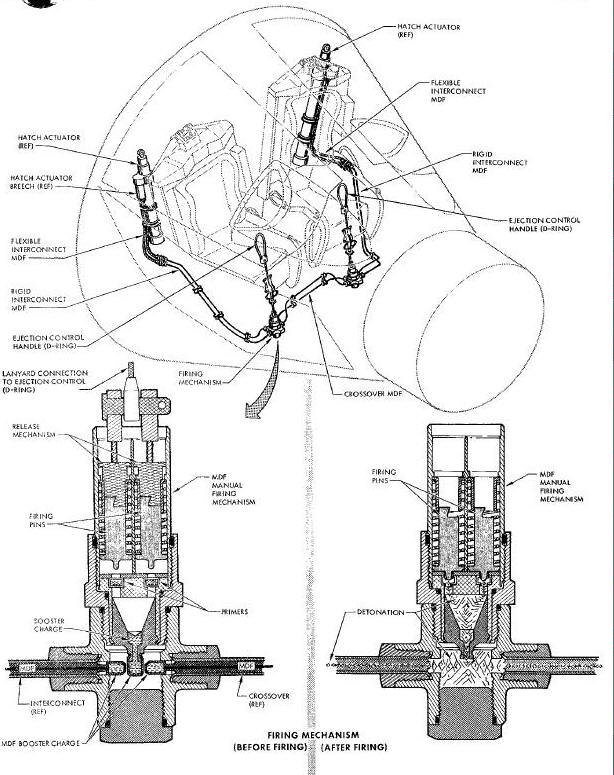
The hatch actuator initiation system is activated when either pilot pulls the ejection control handle (D-ring) located between the pilots knees and connected to the firing mechanism. Approximately one-half inch travel and approximately a 40 pound pull of the lanyard connecting the ejection control (D-ring) to the firing mechanism will cock and release the dual firing pins. The firing pins strike the dual percussion primers, causing the booster charge to detonate. The firing mechanism booster charge propagates detonation to the four MDF ends. The interconnecting MDF propagates the detonation wave to the firing pins of the hatch actuator breech assembly. The crossover MDF propagates the detonation wave to the other pilots firing mechanism. This insures initiation of both hatch actuators.
The hatch actuator assembly (The hatch actuator assembly (Figure Below) unlocks, opens and mechanically restrains the hatch in the open position. The assembly also furnishes sufficient pressure to initiate the firing mechanism of the seat ejector rocket/catapult. The assembly primarily consists of the breech end cap, breech, cylinder, stretcher assembly, end cap (base) and rod end assembly. The breech end cap assembly contains the locking mechanism for mechanically restraining the hatch in the open position; provides for installation of the seat ejector rocket/catapult ballistic hose; provides for installation of the breech assembly, and is thread mounted to the top of the cylinder. The breech contains two firing pins, two percussion fired cartridges, and a gas producing propellant charge. Two interconnects, from the hatch actuator initiation system, are attached to the breech adjacent to the firing pins. The stretcher assembly primarily consists of the piston and stretch link, and is located inside the cylinder. One end of the stretch link is attached to a web inside the piston. The other end is attached to the rod end assembly. The rod end assembly connects the stretcher assembly to the hatch. The end cap is attached to the lower end of the cylinder, and provides for attaching the hatch actuator assembly to the spacecraft structure. The end cap contains a latch piston that actuates the hatch unlock mechanism.
Hatch Actuator Assembly Diagram
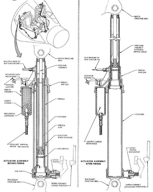
The hatch actuator functions when initiated by the initiation system MDF interconnects. The shock wave, propagated by the MDF interconnects, causes the two firing pins of the breech assembly to sever shear pins and strike the primers of the two percussion fired cartridges. The cartridges ignite and generate hot gas which ignites the main propellant charge of the breech. The propellant charge produces a large volume of high pressure gas. The gas pressure is exhausted into the area between the piston of the stretcher assembly and the cylinder. Orifices in the lower end of the piston wall admit the gas pressure to the base of the stretcher assembly. The gas pressure is ported through a drilled passage to the latch piston. The gas pressure extends the latch piston, which unlocks the hatch through a bellcrank/pushrod mechanism. The gas pressure then acts on the base of the stretcher assembly, moving it through the length of the cylinder. Immediately prior to the stretcher assembly reaching full extension, gas pressure is exhausted through a port to the ballistic hose. The ballistic hose delivers the pressure to the firing mechanism of the seat ejector-rocket/catapult. As the stretcher assembly reaches the fully extended position, the lock pin of the locking mechanism engages the piston of the stretcher assembly and holds the hatch open. The locking mechanism is also operative when the hatch is fully opened by hand. A lanyard, attached to the locking mechanism, permits the hatch to be unlocked, when manually actuated.
The seat ejector-rocket/catapult (Figure Below) is used to eject the man-seat mass from the spacecraft. The seat ejector-rocket/catapult basically consists of the catapult assembly and the rocket motor assembly. The catapult assembly primarily consists of the catapult housing, firing mechanism, main charge (gas producer), and locking assembly. The catapult housing contains all of the listed components in its base. The firing mechanism consists of dual firing pins, dual percussion fired primers, and relay charge. The firing pins are secured in place by retaining pins. The locking assembly consists of the lock ring and a spring to hold the ring in place. The base of the catapult assembly is attached to the spacecraft structure. The rocket motor assembly primarily consists of the motor case, nozzle, motor lock housing, lock ring, shear pins, upper and lower auxiliary igniters, and the main propellant charge. The nozzle is threaded to the motor case and is secured by four set screws. The nozzle is secured to the motor lock housing by locking tangs. The locking tangs are held in place by a lock ring that is retained by four shear pins. The motor lock housing is secured in the base of the catapult by tang locks. The tangs are held in place by the lock ring of the catapult. The main propellant charge is located in the motor case with an auxiliary igniter at each end of the charge. The top end of the rocket motor assembly Is attached to the upper aft portion of the seat.
Seat Ejector - Rocket/Catapult Diagram
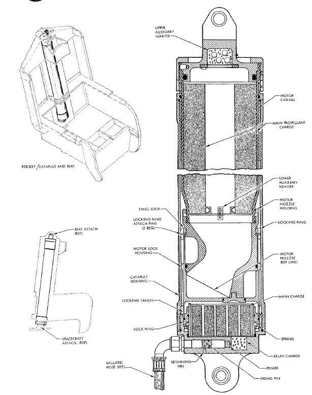
The seat ejection cycle is initiated when gas pressure is received via the ballistic hose from the hatch actuator. Sufficient gas pressure will cause the dual firing plns to shear their retaining pins and strike the dual percussion primers. The primers ignite the relay and main charges. Hot gas pressure, produced by the main charge, releases the motor lock housing by displacing the lock ring against the spring through piston action. With the motor lock housing released, the gas pressure propels the rocket motor through the length of the catapult housing. Prior to complete ejection from the catapult housing, the lock ring of the motor lock housing makes contact with a stop which severs its four shear pins. The tang locks of the motor lock housing cam open and release the rocket motor. Separation of the rocket motor from the motor lock housing allows the hot gas from the catapult main charge to ballistic hose to initiate the thruster assembly.
THRUSTER ASSEMBLY-SEAT/MAN SEPARATOR
The thruster assembly - seat man separator (The thruster assembly - seat man separator (Figure Below) is the active portion of the seat/man separation assembly. The thruster supplies a stroke of adequate length and power to a webbed strap that accomplishes seat/man separation. The thruster assembly primarily consists of the thruster body, thruster piston, firing mechanism and percussion fired gas pressure cartridge. The cartridge and firing mechanism is installed in the upper end of the thruster body. The firing mechanism contains a firing pin, retained by a shear pin. The ballistic hose from the harness release actuator is attached to the firing mechanism. The thruster piston is located in the thruster body and is retained in the retracted position by a shear pin. The thruster body is mounted on the front of the seat structure, between the pilots feet.
Harness Release Actuator Assembly Diagram
High pressure gas from the harness release actuator is transmitted through the ballistic hose to the thruster firing mechanism. The gas pressure causes the firing pin to sever its shear pin and strike the primer of the cartridge. The cartridge is ignited and generates gas pressure. The gas pressure exerts force on the thruster piston, causing the piston to sever its shear pin. As the piston extends out of the thruster body, the strap is pulled taut effecting seat/man separation.
BALLUTE DEPLOY AND RELEASE SYSTEM
The ballute deploy and release system (Figure Below) primarily consists of the firing assembly, deploy cutter and hose, and release guillotine and hose. Contained within the firing assembly, is the release aneroid firing mechanism and cartridge, the deploy firing mechanism and cartridge, and the sequencing housing and piston. The basic function of the system is to deploy and release the ballute between specified altitudes and prevent ballute deployment below specified altitudes. The system is located on the upper left side of each pilots backboard. The deploy firing mechanism and the release aneroid firing mechanism is linked to the pilots seat by individual lanyards.
Ballute Deploy and Release System Diagram
The system is initiated by the lanyard pull as seat/man separation is effected. When initiated above 7500 feet, the release aneroid is armed and the deploy firing mechanism Is activated. The firing pin of the deploy firing mechanism strikes the primer of the cartridge and causes ignition. The cartridge generates gas pressure after burning through the time delay column. The pressure is ported through the deploy hose to the deploy cutter assembly. The cutter severs a nylon strap that allows the ballute to deploy. The armed aneroid functions when an altitude pressure level of 7500 feet is reached. The aneroid sear releases the cocked firing pin of the ballute release firing mechanism. The firing pin strikes the primer, which ignites the cartridge and causes it to generate gas pressure. The pressure is ported through the release hose to the release guillotines The guillotine severs the ballute riser strap and allows the ballute to be carried away. When the system is activated by the lanyard pull below 7500 feet, both cartridges are immediately initiated. The time delay incorporated in the deploy cartridge permits the release cartridge to generate gas pressure first. The pressure is ported through the release hose to the release guillotine, whlch severs the ballute riser strap. Simultaneously gas pressure is ported to the sequencing housing and sequencing piston. The piston is actuated, causing it to block the gas exit of the deploy cartridge. The gas pressure, generated by the deploy cartridge, does not reach the deploy cutter, preventing deployment of the ballute.
DROGUE MORTAR-BACKBOARD JETTISON ASSEMBLY
The drogue mortar-backboard jettison assembly is provided to deploy the personnel drogue parachute and to separate the backboard and seat from the pilot.
The drogue mortar (Figure Below) functions to fire a weighted slug with sufficient velocity to forcibly deploy the personnel parachute and to initiate the backboard Jettison assembly firing mechanism. The drogue mortar primarily consists of the mortar body, mortar barrel, drogue slug main cartridge (gas pressure), initiator cartridge (detonator), aneroid assembly, main lanyard, manual lanyard, and the main and manual firing mechanisms. The mortar barrel is threaded into the mortar body and contains the drogue slug. The drogue slug is retained in the barrel by a shear pin. The aneroid assembly is attached to the mortar body and contains the main firing mechanism. The main lanyard is enclosed in a rigid housing to prevent Inadvertent pulling of the lanyard. The housing is attached to the main firing mechanism housing at one end and to a take-up reel at the other. The main lanyard, a fixed length of cable, is attached to the main firing mechanism at one end and to the take-up reel at the other. The take-up reel incorporates an extendable cable that is attached to the ejection seat. The main cartridge is threaded into the mortar body with the primer end, adjacent to the main firing mechanism and the output end in the mortar body pressure cavity. The manual lanyard is enclosed in a flexible conduit to prevent inadvertant pulling of the lanyar. The lanyard Is attached to the manual firing mechanism at one end and to a manual pull handle at the other. The manual firing mechanism Is threaded Into the mortar body. The primer end of the detonator is threaded into the manual firing mechanism, and its output end 90 degrees and adjacent to the main cartridge output area. The drogue mortar is attached to the upper right sled of each pilots backboard.. The lanyard Is attached to the manual firing mechanism at one end and to a manual pull handle at the other. The manual firing mechanism Is threaded Into the mortar body. The primer end of the detonator is threaded into the manual firing mechanism, and its output end 90 degrees and adjacent to the main cartridge output area. The drogue mortar is attached to the upper right sled of each pilots backboard.
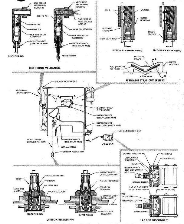
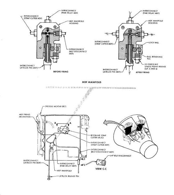
The backboard jettison assembly (Figure Below), functions to separate the backboard and seat from the pilot, when initiated by the pressure from the drogue mortar. The backboard Jettison assembly primarily consists of the MDF firing. mechanism, MDF time delay cartridge (detonator), interconnect (time delay MDF), MDF manifold assembly, Jetelox release pin, interconnect (Jetelox pin MDF), lap belt disconnect, interconnect (belt disconnect MDF), restraint strap cutter (FLSC), and interconnect (strap cutter MDF). The MDF firing mechanism Is attached to the drogue mortar body and contains a shear pinretained firing pin. The MDF time delay cartridge is a percussion fired cartridge and Is installed in the MDF firing mechanism. The interconnect (time delay MDF) is connected to the MDF firing mechanism and the MDF manifold. The interconnect (retained firing pin. The MDF time delay cartridge is a percussion fired cartridge and Is installed in the MDF firing mechanism. The interconnect (time delay MDF) is connected to the MDF firing mechanism and the MDF manifold. The interconnect (Jetelox pin MDF) is connected to the MDF manifold and the Jetelox release pin. The interconnect (belt disconnect MDF) is connected to the MDF manifold and the lap belt disconnect. The interconnect (strap cutter MDF) Is connected to the MDF manifold and the restraint strap cutter (FLSC). The three component interconnects terminate in the MDF manifold with their acceptor end adjacent to the interconnect (time delay MDF) donor end. The Jetelox release pin retains the Jetelox Joint to the seat until initiated. The Jetelox release pin primarily consists of the body, piston, four lock balls, and a shear pin. The lap belt disconnect is provided to unfasten the lap belt when properly initiated. The lap belt disconnect primarily consists of the housing, two lock pins, two cams, piston and a shear pin. The restraint strap cutter is provided to sever the pilots shoulder harness. The cutter primarily consists of the housing, two strips of FLSC and a booster.
Backboard Jettison Assembly Diagram
The drogue mortar is initiated by the pull of the main lanyard, at seat/man separation. The extendable cable, attached to the seat, uncoils from the take-up reel. Upon reaching the end of its travel, the cable pulls the take-up reel free of the rigid housing. The fixed length main lanyard attached to the reel is pulled, and if in excess of 5,700 feet, cocks the main firing mechanism and arms the aneroid. At an altitude pressure level of 5,700 feet, the aneroid releases the cocked main firing pin. The firing pin strikes the primer and ignites the main cartridge, which produces gas pressure. The gas pressure causes the drogue slug to sever its shear pin and travel out of the mortar barrel. Simultaneously, the gas pressure initiates the backboard firing mechanism. When initiated by the main lanyard below 5,700 feet, the main firing mechanism is cocked and immediately released to fire the main cartridge. The aneroid is in the release position because of the altitude pressure level, therefore is not armed and does not delay the cartridge firing. The drogue mortar may be initiated manually by pulling the manual lanyard handle at any altitude. The lanyard cocks and releases the manual firing pin, which strikes the primer of the initiator cartridge (detonator). The initiator cartridge detonates and ignites the output charge of the main cartridge, which produces the gas pressure for drogue slug ejection and backboard firing mechanism initiation.
The backboard jettison assembly is caused to function when the main cartridge of the drogue mortar is fired. Gas pressure from the drogue mortar main cartridge, causes the firing pin of the backboard firing mechanism, to sever its shear pin and strike the primer of the time delay cartridge. After the proper time delay, the cartridge propagates a detonation wave to the MDF interconnect, which transmits the wave simultaneously, to the three MDF interconnects attached to the MDF manifold assembly. Simultaneously, the detonation wave is propagated by the three MDF interconnects to the restraint strap cutter (FLSC), lap belt disconnect, and the Jetelox release pin. The detonation wave propagated by the interconnect (Jetelox pin MDF) acts upon the piston of the Jetelox pin, causing it to sever the shear pin. As the piston moves, a recess in the piston is aligned with the lock balls. The pressure exerted by the Jetelox Joint, forces the lock balls into the piston recess, and releases the Jetelox joint and egress kit. The detonation wave, propagated by the interconnect (belt disconnect MDF), is directed against the piston of the lap belt disconnect. The detonation wave moves the piston causing it to sever the shear pin. As the piston moves, the cams rotate and retract the pins from the lap belt adjuster. The lap belt separates and permits the pilot to be partially free of the backboard. The detonation wave, propagated by the interconnect (strap cutter MDF), is transmitted to the booster of the restraint strap cutter (FLSC). The booster strengthens and increases the reliability of the detonation wave for proper detonation of the two strips of FLSC. The FLSC detonates and severs the two restraint straps allowing the pilot to be completely free of the backboard. The seat may be released manually by the pilot actuating the seat single point release handle. Effective spacecraft 5 and 6 a cable from the single point release, pulls a ball retaining pin from the MDF manifold. The pressure of the interconnect (Jetelox pin MDF), moves the ball aside and pulls out of the MDF manifold.
PARACHUTE LANDING SYSTEM PYROTECHNICS
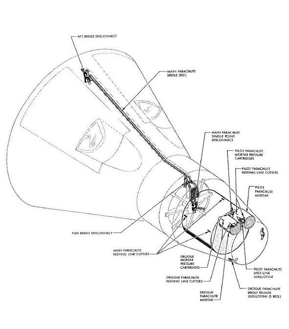
The Parachute Landing System (Figure Below) is provided to safely recover and land the re-entry module, after its entry into the earths atmosphere. The pyrotechnic portion of the system consists of the drogue, pilot, and main parachute reefing cutters; the drogue and pilot parachute mortars; the drogue parachute bridle release guillotines; the pilot parachute apex line guillotine; and the main parachute disconnects. Each of these pyrotechnic devices are presented in the following paragraphs.
Parachute Landing System Pyrotechnics Diagram
DROGUE PARACHUTE MORTAR ASSEMBLY
The drogue parachute mortar assembly is provided to positively deploy the drogue chute. The assembly is similiar to the pilot parachute mortar assembly (Figure Above) in design and operation.
Pilot Parachute Mortar Assembly Diagram
DROGUE PARACHUTE REEFING CUTTERS
The drogue parachute reefing cutters are provided to disreef the drogue chute. The cutters are similar to the pilot parachute reefing cutters (Figure Above) in design, operation, and number.
DROGUE PARACHUTE BRIDLE RELEASE GUILLOTINES
The drogue parachute bridle release guillotines are provided to sever the bridle at its three attach points. The release guillotines are similar in design and operation to the cable and wire bundle guillotine (Figure Above).
PILOT PARACHUTE MORTAR ASSEMBLY
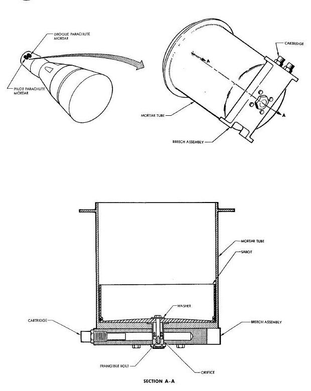
The pilot parachute mortar assembly (Figure Above) functions to deploy the pilot parachute in the event of a malfunctioning drogue chute. The mortar assembly is located in the forward end of the rendezvous and recovery section. The mortar assembly primarily consists of the mortar tube, sabot, breech, orifice, frangible bolt, washer and two electrically fired gas pressure cartridges. The base of the mortar tube is attached to the breech and the breech is attached to the rendezvous and recovery section structure. The flanged orifice passes through the base of the mortar tube and breech. The orifice is secured beneath the breech by a locknut. One end of the breech is drilled and tapped to provide for installation of the two cartridges. The sabot is located in the lower section of the mortar tube and is secured by a washer and a frangible bolt. The frangible bolt passes through the washers, the center of the sabot mortar tube base, and is threaded into the base of the orifice. The pilot chute is installed in the sabot.
The mortar functions when the cartridges are
initiated by a 28 vdc electrical signal. The cartridges generate gas
pressure that is ported through the breech and orifice to the base of
the sabot. When sufficient pressure is exerted on the sabot, the
frangible bolt will part and release the sabot. The gas pressure propels
the sabot and pilot chute out of the mortar tube, thus effecting
positive
chute deployment.
PILOT PARACHUTE REEFING CUTTERS
The pilot parachute reefing cutters (Figure Below) are provided to disreef the pilot chute by severing the reefing line. The reefing cutters primarily consist of the cutter body, cutter blade, firing mechanism and percussion fired time delay cartridge. Two cutter assemblies are sewn to the inside of the parachute skirt band 180 degrees apart. The reefing cutter is a tubular device, with all itst chute by severing the reefing line. The reefing cutters primarily consist of the cutter body, cutter blade, firing mechanism and percussion fired time delay cartridge. Two cutter assemblies are sewn to the inside of the parachute skirt band 180 degrees apart. The reefing cutter is a tubular device, with all its components contained within the cutter body. The firing mechanism is contained in one end of the cutter body and consists of a firing pin, lock ball, spring, and sear pin. The firing pin is retained in the cocked position by the lock ball. The lock ball is held in place by the sear pin. A lanyard is attached to the sear pin and to the parachute canopy. The spring is precocked and energizes the firing pin when the sear pin is pulled. The cartridge is installed in the center portion of the cutter body and is roll crimped in place. The cartridge consists of a percussion primer, time delay column and output charge. The cutter blade is stake locked in the cutter body, below and adjacent to the output end of the cartridge. A washer is crimp locked in the end of the cutter body, and serves as the anvil and stop for the cutter blade. A hole in each side of the cutter body, between the cutter blade and washer, permits installation of the reefing cable.
Pilot Parachute Reefing Cutters Diagram
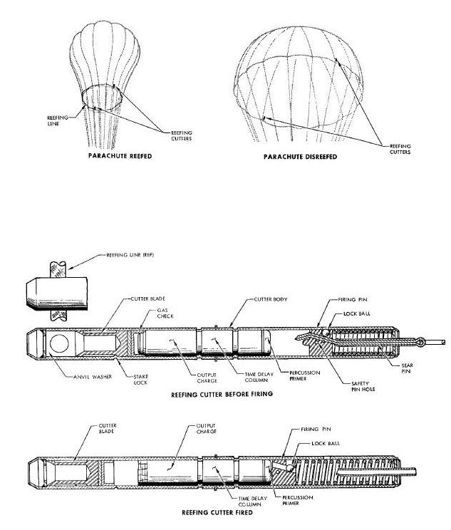
Deployment of the pilot chute causes the reefing cutters to be initiated. As the canopy extends, the lanyard is pulled taut and pulls the sear pin from the firing mechanism. The lock ball moves inboard and unlocks the firing pin. The spring energized firing pin is driven into the primer of the cartridge and ignites the time delay column. After the specified time delay, the cartridge produces gas pressure that exerts force on the cutter blade. When sufficient force is exerted the cutter blade shears the stake lock and strokes to sever the reefing cable. Proper functioning of only one of the two cutters is sufficient to perform pilot chute disreefing.
PILOT PARACHUTE APEX LINE GUILLOTINEE
The pilot parachute apex line guillotine (Figure Below) is provided to sever the pilot chute apex line, in the event of a drogue chute malfunction. The guillotine primarily consists of the body, cutter blade, and two electrically fired gas pressure cartridges. The cutter blade is retained by a shear pin. The body provides for the installation of the two cartridges, and incorporates drilled passages from the cartridges to the cutter blade. Design of the guillotine allows the apex line to pull free, when the pilot chute is deployed by the drogue chute. The guillotine is located in the forward section of the rendezvous and recovery section.
Pilot Parachute Apex Line Guillotine Diagram
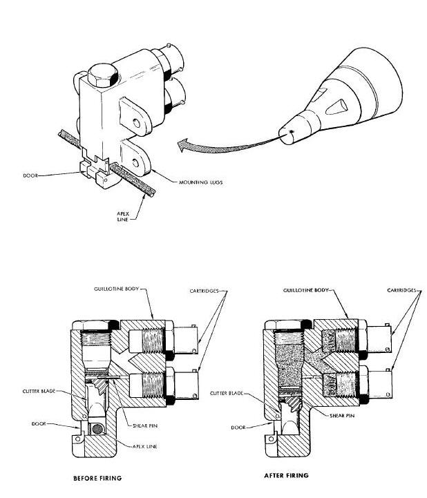
When initiated by a 28 vdc electrical signal, the cartridges produce gas pressure. The pressure is ported through a drilled passage to the head of the cutter blade. Sufficient pressure causes the cutter blade to sever the shear pin and stroke to cut the apex line. The apex line is thus free of the malfunctioned drogue chute, permitting mortar deployment of the pilot chute.
The main parachute reefing cutter (Figure Below) is provided to disreef the main parachute. Three reefing cutters are located on the inside of the canopy skirt band 120 degrees apart. The reefing cutters are similar in design and identical in operation to the pilot chute reefing cutters. Proper operation of only one of the three cutters is sufficient to dlsreef the parachute.
The main parachute disconnects (Figure Below) include the single point disconnect assembly and the forward and aft bridle disconnect assemblies. The disconnect assemblies are identical, in design and function. The disconnect assemblies primarily consist of the breech assembly, arm, and two electrically fired gas pressure cartridges. The breech assembly consists of the adapter, piston, lead slug, snubber disc, and plunger. The piston is retained in the adapter by a shear pin. The lead slug is located on the end of the piston. The snubber disc is located under the head of the plunger. The adapter is threaded into the spacecraft structure with the piston extending into the arm. The breech is threaded onto the adapter and the cartridges are installed in the breech. The single point disconnect is mounted on the hub of the main parachute adapter assembly. The adapter assembly is located on the forward ring of the Re-entry Control System section. The forward bridle disconnect is mounted at the top of the forward ring of the Re-entry Control System section. The aft bridle disconnect is located fox-ward of the heat shield between the crew hatches.
Main Parachute Disconnects Diagram
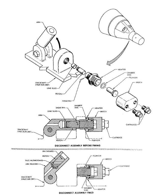
When initiated by a 28 vdc electrical signal, the disconnect cartridges are ignited. The cartridges produce gas pressure that is ported through drilled passages in the breech, to a common chamber at the head of the plunger. The gas pressure exerts a force on the head of the plunger, which in turn propels the piston by physical contact. The piston severs the shear pin and is driven into the arm. The plunger is prevented from following the piston, since the head of the plunger strikes a shoulder in the adapter. The snubber disc provides a cushioning effect, to prevent shearing the plunger head. As the piston strikes the back of the arm, the lead slug at the end of the piston mushrooms. Mushrooming of the slug, retains the piston in the arm, preventing the piston from hindering arm operation. The pull of the parachute causes the arm to cam open, thus releasing the riser or bridle.
Pyrotechnic valves(Figure
Below)are installed in the Orbit Attitude and Maneuvering
System(OAMS)and in the Re-entry Control System(RCS). The valves are one
time actuating devices, used to control the flow of fluids. The
spacecraft contains pyrotechnic valves that consist of the electrically
fired high explosive cartridge, valve body, nipple, ram, seal, and
screw. The nipple, either open or closed depending on the particular
valve, is installed in the valve body and welded into place. The ram,
incorporating the seal and screw at its head is located in the valve
body, indexed directly above the center of the nipple. The cartridge is
installed in the valve body at the top of the ram head. Two types of
valves are used; normally open and normally closed. The "A" packages of
the RCS and OAMS, contain a normally closed non-replaceable valve. The
"E" package of the OAMS contain a normally open, and a normally closed,
nonreplaceable valve. If the valves in the "A" and "E" packages are
defective, or the cartridge has been fired, the packages must be
changed. The "C" and "D" packages of the RCS and the 0AMS contain
normally closed replaceable valves. These valves are attached to the
exterior of the package, and if defective or the cartridge fired, may be
changed individually.
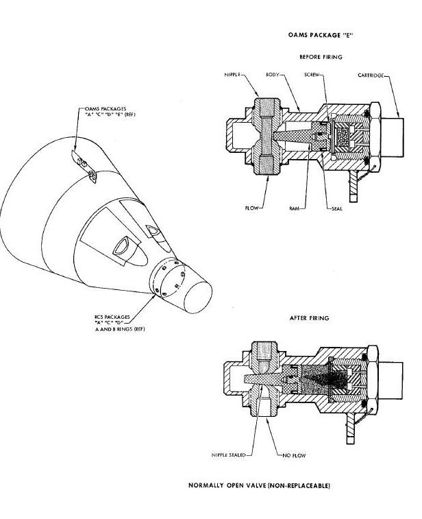
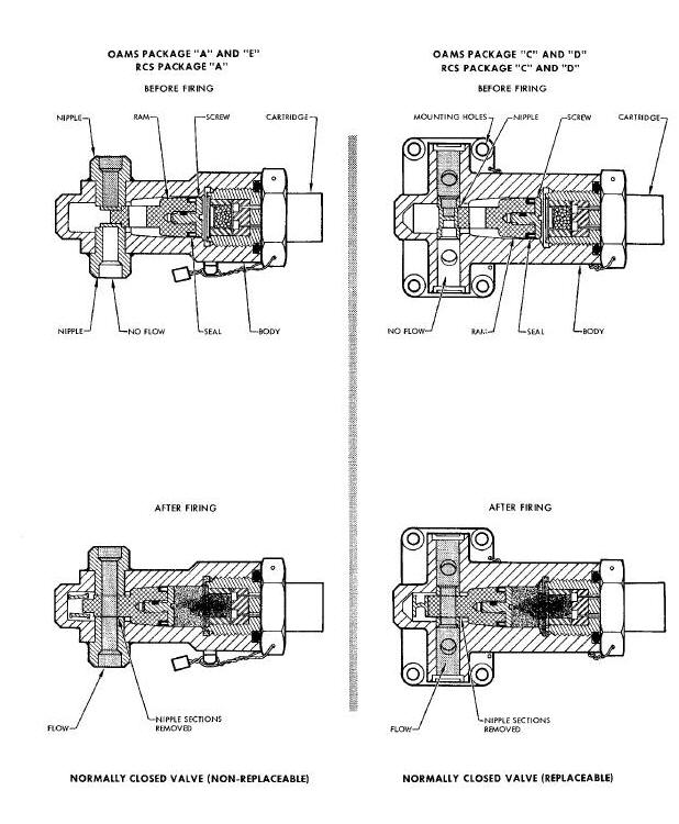
Normally open valve; the pyrotechnic valve is caused to function when the cartridge is initiated by a 28 vdc electrical signal. Ignition of the cartridge produces gas pressure that acts on the head of the ram. The ram is driven down on the nipple, severing and removing a section of the nipple. The ram, having a tapered cross section, is wedged in the nippled opening, completely sealing the nipple, thus stopping the flow of fluid. Normally closed pyrotechnic valves are all basically identical except for nipple design. The non-replaceable valve has two closed end nipples butted together. The ram severs and removes the end of each nipple and wedges itself between the ends. A hole is incorporated in the ram, allowing fluid flow after ram actuation. The replaceable pyrotechnic valve has a nipple installed with a bulkhead in the cross section that stops fluid flow. The ram removes the section of the nipple containing the bulkhead and wedges itself in place. A hole incorporated in the ram allows fluid to flow.
The retrograde rocket system (Figure Below) primarily consists of four solid propellant rocket motors and eight igniter assemblies. The retrograde rockets are provided to retard spacecraft orbital velocity for re-entry and to provide distance and velocity to clear the launch vehicle in the event of an abort during ascent. The rocket motors are symmetrically located about the longitudinal axis of the spacecraft and are mounted in the retrograde section of the adapter. The rocket motors are individually, optically aligned prior to mating the adapter to the re-entry module.
Retrograde Rocket System Diagram
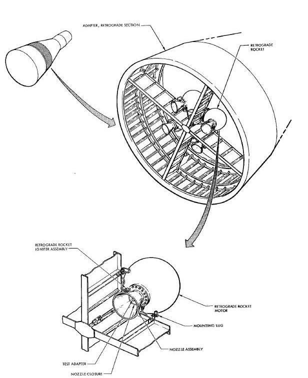
RETROGRADE ROCKET MOTOR ASSEMBLYY
The spacecraft contains four retrograde rocket motor assemblies (Figure Below) that are identical in design and performance, spherical in shape, and are approximately 13 inches in diameter.
Retrograde Rocket Motor Assembly Diagram
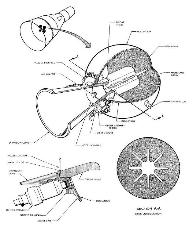
The motor case is formed from titanium alloy in two hemispherical sections. The halves are forged, machined, and welded together at the equator. Each hemisphere is insulated to reduce heat transfer during motor operation. The aft hemisphere is drilled and tapped to provide a mating flange for the nozzle assembly. The nozzle assembly, a partially submerged type, consists of the expansion cone, throat insert and nozzle bulkhead. The nozzle bulkhead is a machined titanium alloy, bolted to the flange at the aft end of the motor case. The bulkhead is threaded to provide for expansion cone installation. The expansion cone is compression molded of vitreous silica phenolic resin and is threaded into the nozzle bulkhead. The throat insert is machined from high density graphite and is pressed into the nozzle bulkhead. The throat insert is insulated from the bulkhead by a plastic material to reduce heat transfer during motor operation. The throat insert is recessed into the motor case to reduce nozzle assembly length. A rubber nozzle closure is sandwiched between the throat insert and the nozzle bulkhead. The closure incorporates a shear groove that permits ejection at a predetermined internal pressure level, or basically at motor ignition. A test adapter fitting is incorporated in the closure to permit pressure checking of the rocket motor.
The motor case is lined with a rubber material that provides propellant grain to case adhesion. The rocket motor propellant is cast and cured in the motor case. The propellant grain is cast in an internal burning eight pointed star configuration. The propellant grain is ignited by the two igniter assemblies, mounted 180 degrees apart on the aft end of the motor case, adjacent to the nozzle assembly.
The retrograde rocket motors function in two modes: normal and abort. In the normal mode of operation, the rocket motors are used to initiate spacecraft re-entry. The rocket motors are fired at 5.5 second intervals in 1-2-3-4 order. The propellant grain of the rocket motor is ignited by the hot gases from the igniter assemblies. The propellant grain burns over the entire surface of its eight pointed star configuration until exhausted. The thrust produced by the motors is transmitted to the spacecraft structure and retards spacecraft velocity. In the abort mode of operation, the rocket motors are fired in salve or as mission requirements may direct.
RETROGRADE ROCKET IGNITER ASSEMBLY
The retrograde rocket igniter assemblies (Figure
Below) are used to ignite the propellant grain of the retrograde
rocket motor. The spacecraft contains eight igniter assemblies that
primarily consist of the case, head cap, grain, booster pellets, pellet
basket, and initiator. The igniter assembly is essentially a small solid
propellant rocket motor. The case and head cap are individually machined
from a stainless steel alloy and have a threaded interface. On the
internal surface of the case, at the gas exit, a silica-phenolic
insulating material is bonded to reduce heat transfer during igniter
firing. The grain is cast and cured in a phenolic paper tube. The grain
is inserted into the igniter case prior to case and head cap assembly.
The booster pellets, consisting of boron potassium nitrate, are
contained in the pellet basket, located in the head cap. The pellet
basket is held in place by the head cap and is installed prior to
case and head cap mating. The initiator cartridge consists of the body,
one firing circuit (bridge wire), ignition mix, and output charge. The
basic function of the initiator is to fire the igniter. The initiator is
threaded into the head cap of the igniter at the time of igniter
assembly build up at the vendors.
Retrograde Rocket Igniter Assembly Diagram
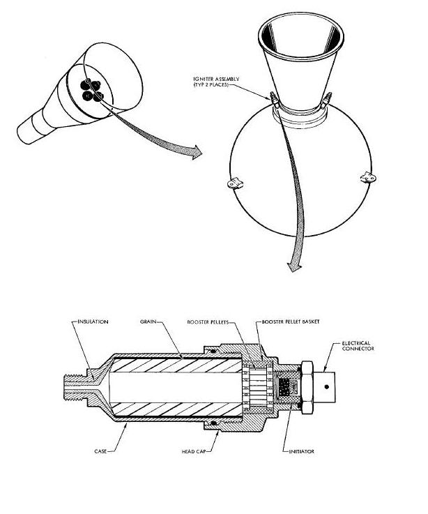
When initiated by a 28 vdc electrical signal, the initiator of the igniter assembly is activated. The initiator ignites the boron pellets, which boosts the burning to the igniter grain. The igniter grain generates hot gas which is exhausted into the retrograde rocket motor cavity. The hot gases provide the temperature and pressure for retrograde rocket motor propellant grain ignition. Either igniter is sufficient to initiate burning of the rocket motor.
DOCKING SYSTEM PYROTECHNIC DEVICES
The pyrotechnic devices utilized for docking are located in the R and R section of the spacecraft (Figure Above). The pyrotechnic devices utilized for docking consist of:
(a) A pyrotechnically actuated indexing bar to
aid the astronauts in matlng
the spacecraft with the TDA.
(b) Three pyrotechnically ejected latch receptacles.
(e) Three pyrotechnically actuated cable cutters to release the three latch covers.
The docking bar assembly (Figure Below) primarily consists of the cylinder, inner piston, inner piston extension, cutter piston, indexing bar, housing/manifold, two breeches, extension cartridge, two jettison cartridges, and a locking mechanism. The basic function of the assembly is to extend and lock the indexing bar, prior to the docking maneuver and to jettison the indexing bar after the docking operations are completed. The purpose of the indexing bar is to aid both visually and mechanically in the docking maneuver. The docking bar assembly is located in the rendezvous and recovery section and attached to the section structure. The housing/manifold, mounted at the top of the cylinder, contains the locking mechanism and provides for installation of two breeches. The breeches provide for the installation of cartridges. One extension cartridge is installed in the extension breech on the left hand side of the manifold and two jettison cartridges are installed in the jettison breech on the right hand side of the manifold.
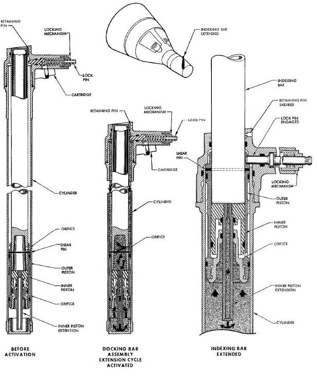

The hollow inner piston extension protrudes through the cutter piston base and is attached to the inner piston. The indexing bar is secured to the outer piston by a shear pin and retained in the cylinder by a retaining pin.
The indexing bar is extended by the gas pressure generated when the extension cartridge is initiated by a 28 vdc signal. The gas pressure is ported into the cylinder and enters an orifice in the base of the indexing bar. The gas pressure is then ported through the hollow inner piston extension and exerts force on the bottom of the outer piston, causing it to sever the retaining pin and extend the outer piston with indexing bar attached. When fully extended, the indexing bar is secured in place by the pin of the locking mechanism engaging a groove in the outer piston. The extension cartridge has dual bridge wires with a separate electrical circuit to each bridge wire for redundancy. The indexing bar is jettisoned when the dual jettison cartridges are initiated by a 28 vdc electrical signal. The gas pressure generated by the jettison cartridges is ported into the cylinder and through an orifice in the outer piston to a cavity between the inner and outer pistons. The thrusting action of the inner piston causes the index bar to sever the shear pin and be jettisoned. Both the inner piston and the indexing bar are Jettisoned. Initiation of only one jettison cartridge is sufficient to jettison the indexing bar. The jettison cartridges have a two second pyrotechnic time delay to assure that during an abort mode the extend cartridge will be firing first to extend the bar before the Jettison cycle is initiated.
EMERGENCY DOCKING RELEASE SYSTEMM
The emergency docking release system (Figure Below) contains three release assemblies located symmetrically about the longitudinal axis and attached to the rendezvous and recovery structure at the outer mold line. The basic function of the release system is to positively release the spacecraft from the docking vehicle in the event of normal release system failure. The release assemblies primarily consist of a latch pen, body, piston closure cap stud assembly and two gas pressure cartridges. The release body is attached at the opposite side of a common structural member of the rendezvous and recovery section. A stud assembly, torqued into the docking release piston protrudes out of the unit body. The latch pan is secured to the stud by a collar and shear pin. Installation of the closure cap seals the area above the release piston. Each unit is activated by two pyrotechnic cartridges, installed in the base of the release body.
Emergency Docking Release System Diagram
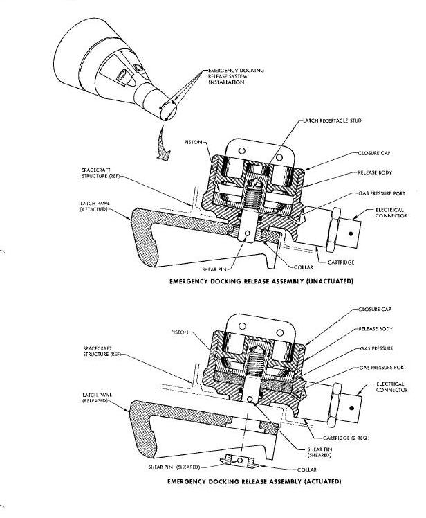
Malfunction of the normal docking release system requires the use of the emergency docking release system. Upon receipt of a 28 vdc electrical signal, the cartridges are ignited in all three release assemblies. The cartridges generate gas pressure that is ported through drilled passages in the body to the underside of the piston. The pressure displaces the piston, separating the shear pin from the latch pawl and moving the piston stud up into the body to clear the latch pawl. The latch pawl being held by the docking vehicle latch, is thus parted from the emergency release body. The spacecraft is then free to move out of the docked condition.
The Target Docking Adapter has a single Flexible Linear Shape Charge (FLSC) ring assembly to open and jettison the transponder cover. The jettison assembly consists of one FLSC, installed around the inside edge of the transponder cover, two detonator blocks, two detonators and an explosive ring. The explosive ring is bolted to the TDA under the transponder door. Detonators are inserted in the two detonator blocks, which are installed on the TDA under the explosive ring.
Upon receipt of a 28 vdc electrical signal, the detonators transmit a detonation wave that is propagated to the FLSC. The FLSC detonates, severs and jettisons the transponder door skin. The explosive ring absorbs the shock in back of the blast and protects the transponder and structure from shrapnel. One strand of FLSC is adequate to sever and Jettison the transponder door.
FUEL CELL HYDROGEN TANK VENT ACTUATOR
The fuel cell hydrogen tank vent actuator (Figure Below) is utilized to puncture the hydrogen tank punch-off tube to allow any gas in the void between the inner and outer tank walls to escape after the spacecraft is in orbit, thus increasing the thermal efficiency of system. The hydrogen tank vent actuator assembly consists of a body, piston/cutter blade, shear pin, guard, breech, ballistic hose, and an electrically fired gas pressure cartridge. The body houses the piston/cutter blade which is retained by a shear pin and provides for attachment of the blade guard. The actuator body assembly is bonded and strapped in place on the fuel cell hydrogen tank and connected to the breech by a ballistic hose. The breech contains the gas generating cartridge and is positioned approximately nine inches from the actuator.
H 2 Tank Vent Actuator Assembly Diagram
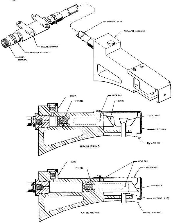
When initiateRd by a 28 vdc electrical signal, the cartridge generates gas pressure that is transferred through a ballistic hose to the actuator body which exerts a force on the piston/cutter blade. The gas pressure causes the piston/cutter blade to move severing the shear pin and splitting the vent tube. The blade guard is attached to the actuator body and forms a barrier which will stop the blade when the piston reaches the end of its stroke.
FLSC - Flexible Linear Shaped Charge (FLSC)
MDF - Mild Detonating Fuse (MDF)
OAMS - Orbit Attitude and Maneuvering System (OAMS)
RCS - Re-entry Control System (RCS)
R&R - Rendezvous and Recovery (R & R)