RENDEZVOUS RADAR SYSTEM
Rendezvous Radar System Diagram
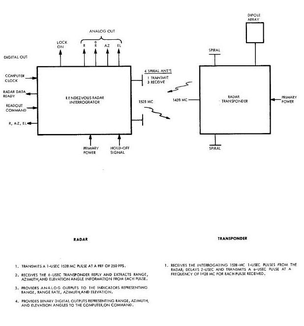
Basic Functions of Rendezvous Radar System Diagram
RADAR MODUIATOR AND TRANSMITTER
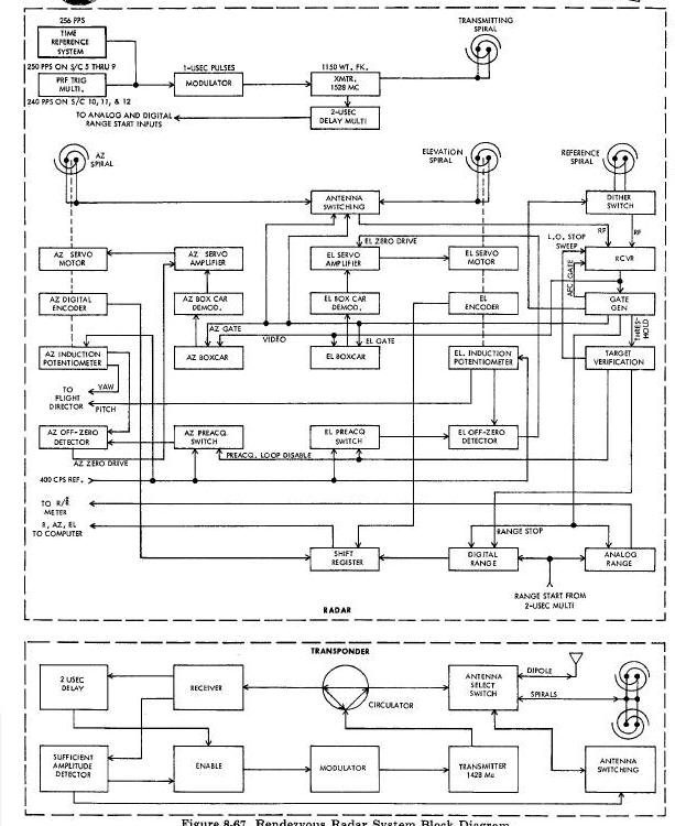
Rendezvous Radar System Block Diagram
Transponder Antenna System Coverage Diagram
Radar/Transponder Receiver Block Diagram
Voltage-Controlled Attenuators
Automatic Frequency Control (AFC)
Radar RF Switching and Return PulseTime Sharing Diagram
Receiver Operation Versus Range Diagram
TRANSPONDER MODULATOR AND TRANSMITTER
RADAR RECEIVING ANTENNA SYSTEM
Azimuth and Elevation Antenna Zeroing
Static Conditions Before Arrival of Return Pulse
Range Threshold Multivibrator Functions
One-Microsecond Multivibrator Functions
Azimuth Two-Microsecond Multivibrator Functions
Interferometer Measurement of Target Angle
ELEVATION TWO-MICROSECOND MULTIVIBRATOR FUNCTIONS
DITHER BISTABLE MULTIVIBRATOR FUNCTION
Interferometer Measurement of Angular Displacement
Spiral Rotation Nulls Error Voltage
Dither Senses Angular Direction
Range and Rang Rate (R/R) Meter
Range/Range Rate Meter and Operating Curve
Compression and Expansion of Meter Scales
Range Sweep Expansion and Compression
Relation of Range to Clock Time
Input Filter and Boost Regulator
Radar and Transponder Power Supply Block Diagrams
Transponder Power Supply Differences
The Rendezvous Radar System (Figure Below) is incorporated in the Gemini Project to facilitate a rendezvous maneuver of the Gemini Spacecraft with the target vehicle. The system is comprised primarily of two units, a radar located in the rendezvous and recovery section of the Gemini and a transponder located in the target docking adapter of the target vehicle. The co-operative operation of the two units enables the detection of the target vehicle by the Gemini and the determination of the range, relative velocity, and angular relationship of the two craft. The radar transmission is also used as a carrier for the command link intelligence; refer to the command link portion of Section VIII for a description of this system.
Rendezvous Radar System Diagram
The Rendezvous Radar System, as described herein is applicable to the rendezvous mission of spacecraft six and those planned for spacecrafts eight through twelve. Spacecraft five utilized a rendezvous evaluation pod to simulate the rendezvous mission. The difference between the rendezvous mission and the rendezvous evalution mission will be discussed in the rendezvous evaluation pod portion of Augmented Target Section.
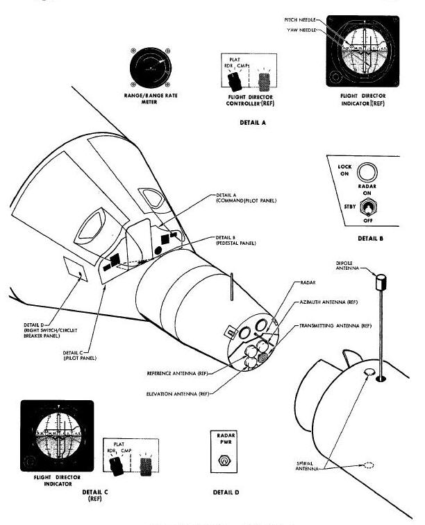
The Rendezvous Radar System is capable of acquiring lock-on when the
target vehicle is within 180 nautical miles of the Gemini and is within
8.5 degrees of the radar boresight axis. The angular acquisition
capability increases to 25 degrees relative to the radar boresight when
the range decreases to within 130 nautical miles. The radar provides
bi-level, analog, and digital outputs for
use during the catch-up and rendezvous portion of the Gemini flight (Figure
Below). The Gemini crew is provided with visual indications
of radar lock-on and Command Link message acceptance. Analog indications
of the target vehicle range and
differential velocity are presented on the Range and Range Rate
Indicator. Analog indications of the elevation and azimuth position of
the target vehicle, with respect to the Gemini, are presented on the
flight director indicators. Digital indications of range, elevation, and
azimuth are available to the computer for calculating the corrective
thrusts required for the rendezvous maneuver.
Basic Functions of Rendezvous Radar System Diagram
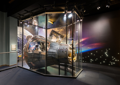
The radar is contained within a pressurized module. The module
dimensions are approximately 17 by 29 by 9 inches, the module area is
1.8 cubic feet, and the weight is 72 pounds. The radar is installed in
the small end of the Gemini Spacecraft on the forward face of the
Rendezvous and Recovery Section.
The radar antenna system consists of four spiral antennas, one uncovered transmit antenna and three covered receive antennas, mounted on the radar face plate. When installed in the spacecraft, the radar is covered with the nose fairing for thermal protection during the launch phase of the mission.
The transponder is contained within an unpressurized module. The module dimensions are approximately 9 by 10 by 24 inches, the module area is 1.25 cubic feet, and the weight is 34 pounds. The transponder is installed in the Target Docking Adapter of the target vehicle.
The transponder antenna system consists of one dipole and two spiral antennas electronically connected by coaxial cables. The dipole antenna is mounted on an extendable boom which is recessed until the extend command is given via the Digital Command System. The spiral antennas are mounted flush with the skin of the Target Docking Adapter and are mounted 180 degrees apart from each
The rendezvous radar will, at the time of launch, be deenergized and the radar will be covered with the nose fairing for thermal protection. At staging plus 45 seconds the pilot will depress the JETT FAIRING switch, thereby Jettisoning the nose fairing and exposing the radar.
During the initial portion of the orbital phase the spacecraft will maneuver to catch up with the target vehicle. This maneuver will place the Gemini and the target vehicle in co-planar, circular orbits. The Gemini will be lagging at a range of approximately 125 nautical miles and closing at a rate of approximately 1.5 nautical miles per minute. After completing the catch-up maneuver the Gemini crew will initiate radar transmlssion.
The radar is placed in the standby mode by switching the RADAR PWR
circuit breaker, located on the right switch/circuit breaker panel, to
ON and the RADAR switch, located on the main instrument panel center
console, to STBY. Those systems with which the radar is interfaced are
energized at this time. A time delay of 60 seconds is allowed for warm
up prior to positioning the RADAR switch
to ON. When turned ON, the radar commences transmission at a frequency
of 1528 megacycles. The transmitted interrogation signal has a pulse
width of 1 microsecond, a pulse repetition rate of 250 pulses per second
for radars in spacecraft five, six, seven, eight, and nine, while those
in spacecraft ten, eleven, and twelve operate at 240 pulses per second.
The transmitter has a peak power
output of 1150 watts.
The transponder will, at the time of launch, be deenergized and the
extendable dipole antenna will be retracted. After the target vehicle
enters the orbital phase the transponder is placed in a standby
condition and the dipole antenna is extended via the Digital Command
System. At this time the transponder is in standby and is connected to
the dipole antenna. A sufficient amplitude detector
is incorporated in the transponder, this circuit detects the initial
pulses from the interrogate radar and enables the high voltage power
supply. The period required for the transponder to become operational is
approximately 12 interrogate pulses or 50 milliseconds. When the high
voltage is energized the transponder is fully operational and will
respond to the interrogate pulses of the radar.
The initial pulses of the radar will energize the transponder high voltage power supply. Now energized, the transponder responds to the radar at the interrogate pulse repetition frequency. The initial reply pulses From the transponder cause the illumination of the LOCK ON lamp.
The rendezvous radar determines the range to the transponder by
observing the events which occur between radar transmission and receipt
of the reply pulse from the transponder. This period of time is
commenced by the time zero pulse, a pulse which occurs simultaneously
with the leading edge of the radar transmission, and is terminated by
the receiver video pulse, the detected transponder reply. The radar
determines analog range by the initiation of a ramp voltage with the
time zero pulse. The ramp voltage continues until stopped by the leading
edge of the transponder reply pulse. The ramp voltage is peak detected
and the resultant dc voltage is proportional to the range. Succeeding
pulses are differentiated to obtain the range rate. The radar analog
range and range
rate voltages are provided to the range and range rate meter and are, by
means of a voltage divider, utilized for telemetry purposes. The radar
measures digital range by counting the number of 50 megacycle computer
clock pulses which occur during the range gate. The digital data is
stored in the shift register for transmission to the computer.
The rendezvous radar determines the angular position of the target
vehicle to the Gemini by observing the phase difference of the rf
received at the reference antenna to the rf received at each of the two
angle antennas. Each of the two angle antennas rotate to nullify the
incoming phase difference. The amount of antenna rotation, from a zero
position, required to achieve this result corresponds directly to the
position error. An induction potentlometer and a Gray Binary Encoder,
used to provide analog and digital intelligence, is
connected to each of the antenna shafts. The analog angle information is
provided to the flight director indicator needles of the attitude
display group. The Gray binary information is converted to serial binary
and stored in the shift register for transmission to the computer.
The radar digital range and angle data is stored in the shift register. The register stores a series of three readings which are continuously updated so as to indicate the latest information. The computer sends a radar data pulse to indicate a request for radar information. The shift register, after receiving the radar data pulse, obtains three complete radar readouts and discontinues updating the information. The radar now transmits a data ready pulse. The computer, upon detecting that the radar data is ready, transmits a series of three bursts of 500 kc pulses to shift the radar data into the computer. The radar at this time returns to the state of continuous data updating.
The radar is utilized during the rendezvous maneuver with the target vehicle as a carrier for the command link information. For information concerning this system refer to the command link portion of Command Link Section. The operation of the radar, as a carrier, is explained herein.
The Command Link System, when energized, disables the radar pulse repetition frequency generator and interconnects the radar and the Time Reference System. The radar now operates at a pulse repetition rate of 256 pulses per second. The radar transmits data by pulse position modulation. The modulation is controlled by a portion of the Command Dink System, the encoder. The normal pulse repetition time of 3900 microseconds is indicative of a zero; a one is transmitted by lengthening this time to 3915.2 microseconds.
The transponder received information is provided to the sub-bit
detector, a portion of the Command Link System. The sub-bit detector
converts the pulse position modulation to binary form and sends the
message to the target vehicle programmer. The programmer verifies that
an acceptable message is received and provides a message acceptance
pulse to the transponder. The message acceptance pulse, when received by
the transponder, causes the transponder transmitted pulse to lengthen
from 6 to 10 microseconds and remain in this condition for three
transmissions. The radar detects the additional pulse width and effects
the illumination of the Message Acceptance (MSG ACPT) lamp.
The previously described system operation affects only the radar pulse repetition frequency. This operation results in no alteration or interruption to the radar system.
RADAR MODUIATOR AND TRANSMITTER
When the RADAR switch is in the STBY position a hold Off signal is applied to the high voltage portion of the radar power supply to prevent it from producing the high voltage required by the transmitter tube. When the pilot places the RADAR switch to the ON position, (Figure Below) the hold off signal is removed, the 1650 volts dc is produced and applied to the transmitter tube, and the radar commences transmitting in the search mode. In the search mode the pulse repetition frequency trigger multivibrator oscillates at 250 cycles per second for radars on spacecraft five, six, seven, eight and nine, while on spacecraft ten, eleven, and twelve the trigger mulivibrator oscillates at 250 cycles per second, generating a square wave which is used to triter the modulator. The modulator output is a series of one microsecond positive pulses which triggers the transmitter tube. The transmitter tube Output is a 1528 megacycle, 1 microsecond, 1150 watt pulse at a repetition rate equal to the output of the pulse repetition frequency trigger multivlbrator. The transmitter output pulse is coupled to the transmitting dual spiral antenna and radiated in order to interrogate the transponder.
Rendezvous Radar System Block Diagram
The transponder utilizes two antenna systems, (Figure Below) a
dipole antenna array and two dual spiral antennas. The selected antenna
system is connected to the transponder by an antenna select switch. The
dipole antenna array is located on an extendable boom which is retracted
until after the target vehicle enters the orbit phase of the mission.
The spiral antennas are located on either
side of the Target Docking Adapter and are mounted flush with the
surface of the adapter (Figure above).
Transponder Antenna System Coverage Diagram
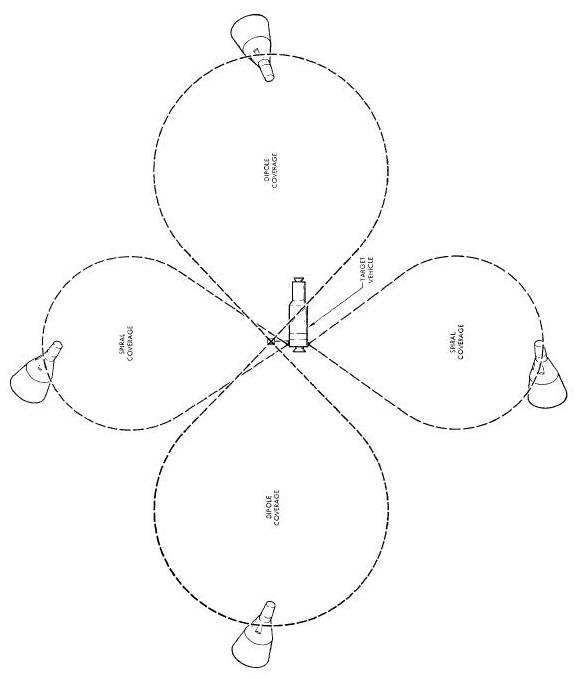
The dual transponder antenna systems are designed to provide
spherical coverage about the target vehicle. The dipole will provide
omnidirectional coverage in the horizontal plane. The dipole pattern is
doughnut shaped with the dipole located in the center. The beam width
considered in any horizontal direction is plus or minus 25 degrees at
the half power points. The array has a minimum
gain of 5.5 db. In order to provide effectively spherical coverage the
spirals will operate in the space above and below the dipole pattern.
The spiral beam width is plus or minus 35 degrees and the minimum gain
of each spiral is 7.5 db.
The initial condition of the transponder will be with the internal circuitry connected to the dipole array and the spiral antennas disconnected. The dipole array is selected since this provides coverage for the anticipated acquisition area. The initial radar pulses received by the transponder enables the sufficient amplitude detector. The detector turns on the high voltage required for transmitter operation, thereafter it monitors the received isignal to ensure adequate strength. Should the signal level decrease below a specific level the detector causes the transponder to switch to the opposite antenna system in search of greater strength.
The signal from the transponder Video circuit is applied to the
Sufficient Amplitude Detector (SAD). During the initial portion of the
mission, when the transponder is in standby, the SAD monitors the
antenna system for the initial interrogate pulse from the radar. When
the first pulses are received it places the transponder in the transmit
mode by activating the high voltage. While the
transponder is operating the SAD monitors the received signal strength;
if it decreases below a specific level it selects the opposite antenna
system in order to seek greater signal strength. Should the interrogate
signal be lost, the SAD causes the transponder to continually cycle from
one mtenna system to the other until lock-on re-occurs.
The transponder circulator (Figure
ABOVE) is a transmit/receive device which permits the receiver
and transmitter to operate by the same antenna. The circulator provides
a low attenuation path for the rf from the transmitter tube to the
antenna and a low attenuation path from the antenna to the receiver. The
directivity of the circulator provides a high attenuation and enables
the
blocking of the main bang from the receiver.
The transponder and radar receivers (Figure Below) are practically identical in most respects. There are some differences, principally in the input circuit. The receiver will he explained in the following way. The difference in the input circuitry will be discussed first, then the portion of the receiver from the bandpass filter to the video circuits output. Automatic frequency control and automatic gain control will conclude the discussion of the receiver.
Radar/Transponder Receiver Block Diagram
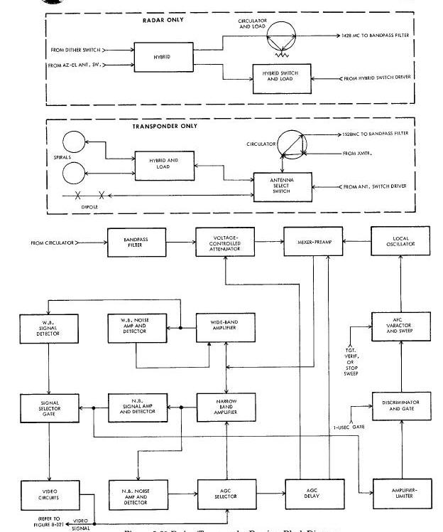
Figure Above shows the three
receiving spiral antennas and the manner in which the rf is connected to
the receiver. As will be discussed later in the radar receiving antenna
system paragraph, the radar compares phase relationships on two
receiving antennas at a time during each return pulse. Because the radar
compares phase relationships while the transponder does not, the input
circuits
are different. The two rf signals being compared in phase are combined
in the hybrid (Figure Above). The signal path of the combined rf is
through the circulator, the bandpass filter, the voltage controlled
attenuator and into the mixer. The load associated with the radar
circulator is required because of the voltage controlled attenuator.
(Refer to the discussion of the voltage controlled
attenuator below, where its operation in both receivers is explained. )
The load associated with the radar hybrid switch is explained in the
gate generator discussion.
As Figure below shows, both spirals are connected to a hybrid. Since only one spiral at a time will be directed toward the radar, the signal received on either one will pass through the hybrid to the antenna select switch. The signal is passed through the circulator, the bandpass filter, and the voltage controlled attenuator to the mixer. The loads associated with the transponder hybrid are required for equal power division in the hybrid. If neither spiral was directed toward the radar, the signal would be received on the dipole, passed through the antenna select switch and on to the mixer in the same way as was described for the spiral.
The bandpass filters in the transponder and the radar are identical; however, the frequencies to which they are tuned are different. Each filter is tuned at the transmit frequency of the other unit. The radar is tuned to 1428 magacycles and the transponder is tuned to 1528 megacycles. These filters provide the required interference rejection and help keep the transmitter main bang out of the receiver.
Voltage-Controlled Attenuators
The voltage controlled attenuators in the radar and the
transponder are identical. The purpose of the attenuator is to prevent
saturation of the mixer by holding the mixer input to a minus 12 dbm
maximum. The attenuator is inoperative at far and middle ranges.
Operation commences as the range decreases and the power at the receiver
increases. The attenuator is a solid-state device with
a maximum attenuation of 24 dbm. The attenuation is controlled by a
delayed automatic gain control voltage which varies from 0 to minus 6
volts.
The voltage-controlled attenuator produces attenuation by impedance mismatching. In the radar, the impedance mismatch tends to reflect the wave hack to the input, which is the circomlator. Due to the directional characteristic of the circulator described earlier, the reflected wave will not back up through the circulator the same way it enters. The path that the reflected wave takes through the circulator termiuatas in a load resistance; thus the reflected wave is prevented from becoming a standing wave. This precaution is taken in the radar because standing waves could upset stability and render the angular measurements inaccurate.
The voltage-controlled attenuator in the transponder functions in a similar manner; however, standing waves are not avoided. Never the less, attenuation is effective, and the mixer is prevented from saturating. Since no critical measurements are made in the transponder the standing waves produce no unfavorable effects.
Automatic Frequency Control (AFC)
The automatic frequency control circuit in the transponder and radar is comprised of the local oscillator, the mixer preamplifier, the narrow band amplifiers and detector, the amplifier limiter, the discriminator and gate, and the AFC varactor and sweep circuit (Figure Above ). The varactor, a solid-state voltage controlled variable capacitor, is the heart of the AFC circuit. A 0.2 cycle per second sweep voltage is applied to the varactor when the receiver is turned on. This voltage causes the local oscillator frequency to vary over a 1-megacycle band about its operating frequency.
In the transponder, when the 1528 megacycle interrogation pulse is
received, it is applied to the mixer. Here the 1557.5 to 1558.5
megacycle output of the local oscillator beats with it, and the 30
megacycle Intermediate Frequency (IF) is produced. The IF is applied to
the wide band and narrow band amplifiers. The signal selector gate
initially selects the narrow band output since it is larger.
Five pulses in 16 milliseconds produce the stop sweep pulse which ends
the local oscillator sweeping. This prepares the varactor to be
controlled by the discrlminator. The narrow band signal is amplified,
limited, and discriminated. If the video exceeds the predetermined
threshold, a 1 microsecond pulse is supplied which opens the
discriminator gate and allows the discriminator output to control the
varactor. The discriminator increases the frequency if it is low,
decreases it if it is high. There is no output from the discriminator
when the IF is exactly 30 megacycles.
In the radar, when the 1428 megacycle return pulse is received, the
1457.5 to 1458.5 megacycle output from the oscillator beats with it.
Twelve pulses in 48 milliseconds are required to produce the target
verification pulse which stops the varactor sweep. The 1 microsecond
multivibrator (Figure below)
produces the discriminator gate which enables the discriminator to
control the varactor.
The IF is maintained to 30 megacycles.
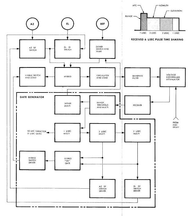
Radar RF Switching and Return PulseTime Sharing Diagram
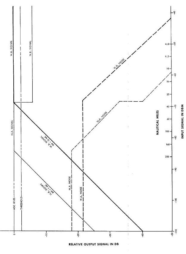
Receiver gain in both the radar and the transponder must be adjusted
automatically to accommodate a wide range of input signal levels.
Figure below shows how the narrow
and the wide band channels are controlled by noise levels, input
signals, and range. The narrow band channel has 14 db higher gain than
the wide band channel. Since the signal selector gate (Figure
above) will select
the higher output to operate the video circuits, the narrow band circuit
will have control at the distant ranges. Narrow band gain will be
controlled by the narrow band noise feedback voltage. When the narrow
band signal assumes control of the narrow band gain, the outputs of the
narrow band noise detector and signal detector are both applied to the
AGC selector. The AGC selector controls the narrow band gain. The wide
band signal has also been increasing with the input signals and the
decreasing range. As the side-band signal reaches the predetermed level,
it is selected by the signal selector gate and assumes control. The wide
band signal applied to the AGC selector along with the narrow band noise
detector output further reduces narrow band gain and narrow band noise.
As range continues to diminish and input signal to increase, a greater
AGO voltage is developed to hold the signal at the predetermined level.
The AGC delay is overcome and AGC is applied to the voltage-controlled
attenuator and the mixer preamplifier at near range. AGC in these
receivers is capable of maintaining a constant output level with input
signals weaker than -83.3 at 160 nautical miles to signals of +12 dbm at
a range of 20 feet.
Receiver Operation Versus Range Diagram
TRANSPONDER MODULATOR AND TRANSMITTER
The transponder transmitter is placed in the standby mode by the uhf command link. A hold off signal is applied to the high voltage portion of the transponder power supply to prevent it from producing the high voltage required by the transmitter tube. The initial interrogate pulses from the radar surpass the threshold of the sufficient amplitude detector and cause the removal of the hold off signal. The 1590 volts dc is produced when the signal is removed and the transmitter commences transmitting. In the transit mode the interrogate pulse from the radar is received at the transponder, delayed for 2 microseconds, and used to trigger the modulator. The modulator output is a 6 microsecond positive pulse which triggers the transmitter tube. The transmitter output is a 1428 megacycle, 6 microsecond, 1150 watt pulse at the interrogate pulse repetition frequency. The transmitter output pulse is coupled through an rf switch to either the pair of spiral antennas or the dipole antenna array and radiated.
RADAR RECEIVING ANTENNA SYSTEM
The radar receiving antenna system consists of three dual spiral antennas 6.5 inches in diameter. The receiving antennas, along with the transmitting antenna, form a square array spaced 0.82 wave length apart. The three receiving antennas are: the azimuth antenna, the elevation antenna, andlthe reference antenna. The azimuth and elevation antennas are rotatable and are pressurized to aid lubrication in the space environment. They are returned to zero rotation by a preacquisition loop. The reference antenna and the transmitting antenna do not rotate and are not pressurized. The spirals are ralsed about a quarter wave length (2-1/8 inches) above the radar face plate, and have a circumference of 2.4 wave lengths (20.5 inches). Their characteristic impedance is 75 ohms. The receiving antennas are operated in pairs, using the reference antenna as the common element, to measure the target bearing angle. The radar uses time sharing of the 6 microsecond return pulse, interferometer measurement techniques, and phase dither to obtain complete tracking information.
Azimuth and Elevation Antenna Zeroing
The amount that the azimuth and/or elevation antenna is rotated is the measure of target position. When the radar is tracking a target and these antennas are following the target's changing position, lock on may be interrupted. When this happens, it is desirable to return the antennas to zero rotation. A circuit called the preacquisltion loop is provided to do this when the target pulse is not being received. The loop consists of the preaquisition switch, a 400 cps reference voltage, output from the induction potentiometers, a detector, the servo amplifiers, and the servo motors.
The loop compares the output of the induction potentiometer with a 400 cps reference voltage. If the antenna is off zero, an error voltage is produced in the detector output. The error voltage drives the servo amplifier which turns the servo motor. As the rotation -angle decreases, so does output of the induction potentiometer; and when the potentiometer output is zero the error voltage and the rotation angle are zero. As soon as lock on is established, this loop is disabled by the target verification signal.
There is a reason why the transponder transmits a 6 microsecond pulse in reply to 1 mlcrosecond interrogation pulse. If only range data and automatic frequency control voltages were obtained from the pulse a similar 1 microsecond pulse would be wide enough; but the azimuth and elevation angle of the target must be obtained from the same pulse. The interferometer technique of angular measurement (which will be described later) required that two antennas in the horizontal plane receive the return signal. The signal on the two horizontal antennas must be present for an interval long enough to compare their phase relationship. Next, 2 two antennas in the vertical plane must receive components of the return signal long enough to compare their phase relationship. In this system, the optimum interval for the phase comparison is 2 microseconds. For this reason the transponder sends hack a 6-microsecond pulse.
The return pulse must be divided into 3 parts each time it is
received. (Figure
8-70). The
first part, one microsecond, will be used for range measurement and
automatic frequency control of the local oscillator and receiver
intermediate frequency. The second part will be used for azimuth angular
measurement, and the third part will be used for elevation angular
measurement. The first
interval will be made 1 microsecond; the second and third, 2
microseconds each. These intervals add up to 5 microseconds; the
remaining 1 microsecond is not used.
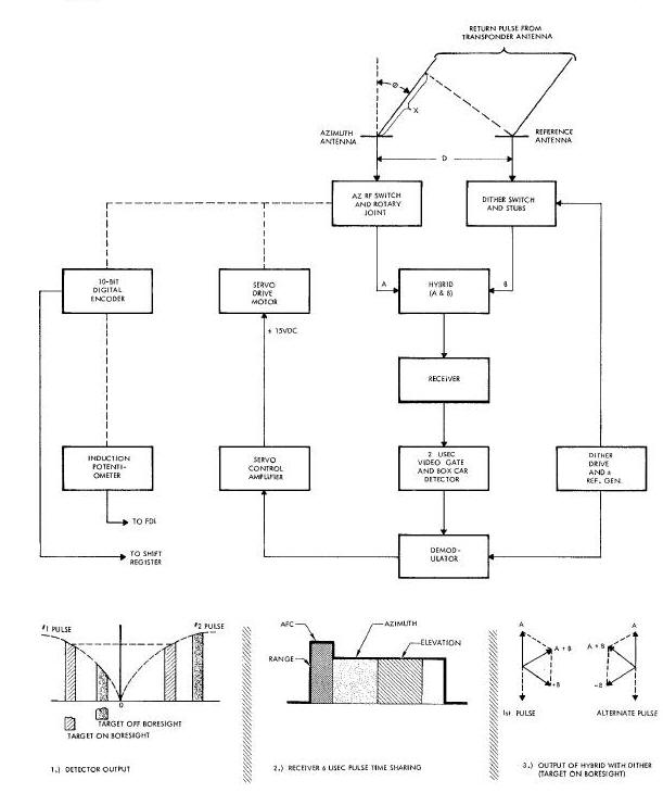
The key circuit which controls pulse division switching and time sharing is the gate generator. Figure Below illustrates how the gates which perform the required switching are generated. To understand the switching that is done, the gates that are generated and used, and how the return pulse time is shared, it is necessary to know the static conditions before the pulse is returned, the return signal path, and the sequence in which the gates and switches operate.
Static Conditions Before Arrival of Return Pulse
While the radar is waiting for the return pulse from the transponder, the following conditions prevail. The azimuth RF switch, the elevation RF switch, and the hybrid switch are open. The open azimuth and elevation switches prevent rf, which arrives on these antennas, from being connected to the hybrid and receiver. Thus this rf cannot be mixed with the reference antenna rf until the proper gate voltage is applied. The open hybrid switch keeps the hybrid load disconnected from the hybrid. The dither switch is closed in one of its two positions. Alt of the multlvibrators (except the dither bistable multtvibrator) are one-kick multivibrators, and in the quiescent state. They are waiting for the return pulse to trigger them in succession.
The reference antenna is the only receiving antenna initially connected to receive the return pulse. Following the arrows from the reference antenna to the input to the gate generator on Figure Below, the signal flow is as follows. The 6-microsecond pulse enters the reference antenna and flows through the dither switch and selected stub, the hybrid, the circulator, the bandpass filter, the voltage-controlled attenuator, and the receiver, and enters the gate generator.
When the transponder pulse arrives at the antenna system, it enters the reference antenna and follows the described path to the gate generator. Here, it is applied as a 6-microsecond video pulse to the range threshold and multivibrator. If the pulse amplitude is large enough, the leading edge of the video pulse triggers the multivibrator. Then the whole process of gating and switching begins.
Range Threshold Multivibrator Functions
The on-period of the range threshold multivibrator is 12
microseconds. This threshold multivibrator has four functions : First,
the leading edge of this 12 microsecond pulse terminates the range
measurement in both the digital and analog range circuits. Second, five
of these pulses are integrated by the target verification circuit to
produce the target verification signal. The target verification
signal stops the AFC sweep (Figure
Above),
and disables the preacquisition loop. Third, the leading edge of the
threshold multivibrator output has no effect on the dither bistable
multivibrator. The dither multivibrator and switch remain locked in
position throughout the return pulse. Fourth, the one-microsecond
multivibrator is triggered by the leading edge of the threshold
multivibrator output.
One-Microsecond Multivibrator Functions
The 1-microsecond multivibrator has three functions: First, it gates the discriminator output into the AFC varactor (Figure Above). This gate permits the output of the discriminator to continually correct the local oscillator frequency to 1458 megacycles. Second, the 1-microsecond gate is applied to the azimuth and elevation boxcar detectors simultaneously. The gate dumps the charges built up in these detectors during the preceding sampling interval. Third, the trailing edge of the l-microsecond gate triggers the R-microsecond multivibrator. (Figure Above)
Azimuth Two-Microsecond Multivibrator Functions
The R-microsecond pulse generated by the azimuth multivibrator is the azimuth gate. This gate performs five functions : First it excites the azimuth rf switch driver. The driver closes the azimuth rf switch. The switch connects the azimuth antenna to the hybrid (Figure Below). Second, the gate enters the hybrid or gate and excites the hybrid switch driver. The driver closes the hybrid switch. The switch connects the load during the azimuth angle measurement. This load flattens the line and prevents standing waves from producing erratic measurements. Third, the gate permits the video received during this interval to develop a charge voltage in the azimuth boxcar detector (Figure Below). The charge voltage is later demodulated to provide the control voltage for the azimuth servo motor. Fourth, when the azimuth gate ends, the azimuth rf switch is opened. The switch disconnects the azimuth antenna (Figure Above ). Fifth, the trailing edge of the azimuth gate triggers the elevation R-microsecond multivibrator.
Interferometer Measurement of Target Angle
ELEVATION TWO-MICROSECOND MULTIVIBRATOR FUNCTIONS
The output of the multivibrator is the elevation gate. It performs five functions: First, it keeps the hybrid switch closed and the load applied to the hybrid. Second, it closes the elevation rf switch and connects the elevation antenna to the hybrid. Third, it permits the video received during this interval to charge the elevation boxcar detector. This voltage charge is later demodulated to become the control voltage for the elevation servo motor. Fourth, the end of the azimuth gate opens the elevation rf switch and disconnects the elevation antenna. Fifth, the end of the gate also ends the drive to the hybrid switch and disconnects the hybrid load.
DITHER BISTABLE MULTIVIBRATOR FUNCTION
The dither bistable multivibrator has one function: to change the position of the double-pole double-throw dither switch. The dither multivibrator is insensitive to the leading edge of the 12-microsecond threshold multivibrator pulse. However, the trailing edge of this pulse will trigger lthe dither multivibrator. Hence, the dither switch and stub are changed 6 microseconds after every return pulse ends.
Interferometer Measurement of Angular Displacement
The method of measuring angular displacement employed fin the Rendezvous Radar System uses rf waves from a point source, the operating transponder antenna (Figure Above). These waves are received simultaneously by two of the three spiral receiving antennas of the Rendezvous Radar. The length of the rf path to the reference antenna is compared first with the length to the azimuth antenna, then with the length to the elevation antenna. The transmission lines from the three receiver antennas are wired so that rf voltage induced in the azimuth and elevation antennas will be 180 degrees out of phase with rf voltage induced in the reference antenna, if the transponder is on the radar boresight axis. The sum of two compared voltages will be zero. If, however, the transponder is off the boresight axis, in azimuth for instance, the path lengths to the reference antenna and to the azimuth antenna will be different. Therefore, the phase difference between the RF voltage induced in the two antennas will not be 180 degrees. As a result, there will not be complete cancellation (or a null) as before. A voltage proportional to the displacement from the boresight axis will result. This voltage is called the error voltage.
Spiral Rotation Nulls Error Voltage
The method used to null out the error voltage constitutes the
interferometer method of angular measurement. This method depends upon a
petculiarlty of the spiral antenna. The spiral antenna shifts the phase
of the rf voltage induced in it as it is rotated about its center.
Therefore, the 180-degree phase difference between the azimuth and
reference antennas can be obtained by rotating
the azimuth antenna. The amount of azimuth antenna rotation required to
get the null is proportional to the target displacement in azimuth. If
the error voltage is used to drive a motor which rotates the azimuth
antenna, then when the null is reached, the error voltage is zero, and
the motor stops rotating. The antenna also stops rotating. If a senseing
device is put on the azimuth antenna which counts the angular rolls of
rotation or generates a voltage proportional to the rotation, a digital
or analog measure of the target's angular displacement in azimuth from
boreslght is provided.
Figure Above
shows that this is what Is done. Displacement in elevation is measured
in a similar manner.
Interferometer measurement of target angle does not yield direction data. Interferometer measurement tells how much the target is of the boresight axis but not in which direction. To establish target direction, dither is added.
Dither Senses Angular Direction
The phase dither circuit contains two single-pole, double throw diode switches and two different lengths of transmission line, called stubs. The diode switches are installed in the transmission line between the reference antenna and the hybrid. One position of the diode switches is associated with the short stub of transmission line, the other position with the long stub. Successive transponder pulses are received in alternate positions of three switches. After each transponder pulse has been received, the positions of the dither switches are changed. Signals from the target on the pilot's left or from below the boresight axis are reinforced by the long stub, weakened by the short stub. Signals from the target on the pilot's right or above the boresight axis are reinforced by the short stub, weakened by the long stub. Signals along the axis are equal on both stubs but oppositely polarized; these signals average out to zero. Since target position is associated with a reinforced signal in a given position of the dither switches, dither can detect target directions.
Range and Rang Rate (R/R) Meter
During the catch-up phase, the closing range rate in feet per second may be equal to or less than the square root of the numerical value of the range in feet. This means, for instance, that at 300,000 feet, the maximum closing range rate is 547 feet per second; at 30,000 feet, 173.2 feet per second; but at 3,000 feet, 51.7 feet per second is maximum. The range and range rate scales are arranged concentrically on the R/R meter so that the range is on a radius directly adjacent to the maximum closing rate. (Figure Below ) Hence, as toward zero, the closing long as the range rate needle precedes the range needle rate is not excessive. When the indicating edges of the needles coincide as the needles move toward zero, the maximum tolerable closing rate is indicated. If the range needle precedes the range rate needle toward zero, the closing rate is excessively high.
Range/Range Rate Meter and Operating Curve
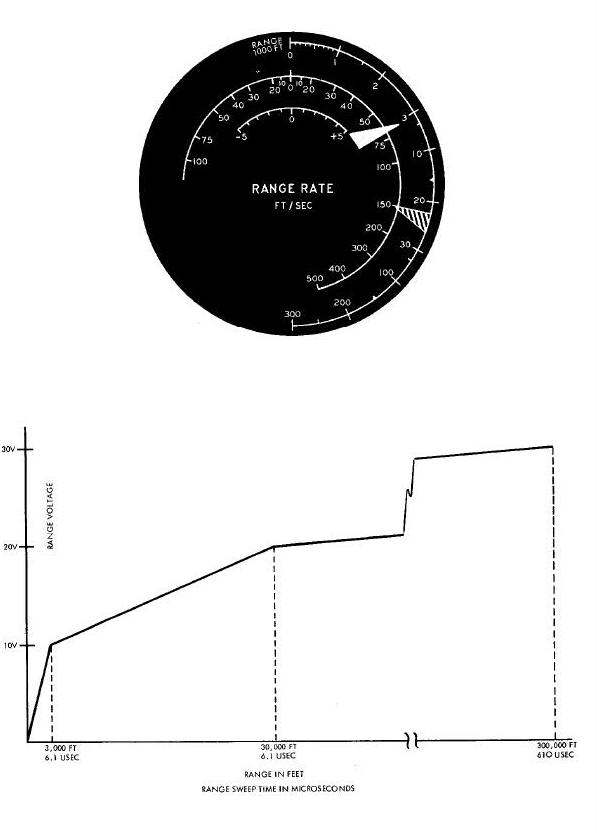
Vernier range rate is indicated in one foot-per-second increments from plus to minus 5 feet per second on the scale located above center on the R/R meter. The indicating needle for the vernier meter is usually off scale and out of sight until the spacecraft is within very near range of the target.
Compression and Expansion of Meter Scales
The range and range rate meter scales are clearly nonlinear. Maximum values are compressed, minimum values are expanded. This is done because precision indications of range and range rate become far more critical as the range to target closes.
Range Sweep Expansion and Compression
In order to make a current-operated meter indicate the range and
range rate with high accuracy, a special range sweep circuit is used (Figure below). The
rate of voltage change with time during the first 6.1 microseconds of
sweep is
the most rapid. Thus the range indication from 0 to 3,000 feet is the
most expanded. During the next 54.9 microseconds of the sweep, the
voltage increased
with time at about 1/9th the rate of the first 6.0 microseconds. The
range indication from 3,000 to 30,000 feet is expanded to a reduced
extent. During the last 549 microseconds of the sweep, the voltage
increases at 1/90th the rate of the first 6.1 microseconds. The range
between 30,000 and 300,000 feet is compressed into a small portion of
the scale. Thus the near range is 9 times more sensitive than the middle
range and 90 times more sensitive than the far range.
Range is measured by sampling the sweep voltage at a time coincident with the leading edge of the transponder return pulse. The sampled voltage is stretched into a dc voltage, and applied to the range meter winding.
Range rate is a function of the difference in range voltages on successive transponder pulses. This voltage difference is monitored, shaped and amplified in a circuit controlled by the same logic that changes the range sweep slope. It is applied as a dc voltage to the range rate meter coil on the far and intermediate ranges, and to the vernier range rate meter coil on the near range.
A high-speed digital counter counts 10-megacycle clock pulses during the range gate to generate the digital range count. (Figure above). The clock pulses are produced by a 10 megacycle crystal-controlled oscillator in the spacecraft radar. The range gate is started 2 microseconds after the leading edge of the interrogating pulse. This 2-microsecond delay compensates for a similar delay through the transponder, The range gate is closed by the leading edge of the transponder pulse.
Relation of Range to Clock Time
One cycle at 10 megacycles equals 0.1 microsecond or 50 feet of radar range. Digital range supplied to the computer is the average of four successive digital counts of the range to the target. Accuracies within 50 feet or O.1 percent of the range (whichever is larger) are obtained for ranges up to 250 nautical miles.
Primary power to operate the rendezvous radar is obtained from the spacecraft source. Voltage from this source may vary between 22 and 30 volts dc, noise and transients produced by various spacecraft equipment will also be present in this power. Filtering of the primary power is essential.
Electrically operated equipment in the spacecraft will reduce the voltage available from the source. The radar requires a means of maintaining its primary power voltage at a high and constant level, even though source voltage is reduced considerably.
Input Filter and Boost Regulator
Unregulated primary power is applied to the radar power supply input. An input filter removes the noise and transients. A boost regulator uses a portion of the filtered primary power to generate a voltage to add in series with the primary voltage. The voltage generated depends on the difference between 31.7 volts dc (the boost regulator output) and the primary voltage. The boost regulator generates 1.7 volts dc and adds it in series when the primary voltage is 30 volts dc. As the primary voltage decreases, the boost regulator output increases by an equal amount (Figure Below).
Radar and Transponder Power Supply Block Diagrams
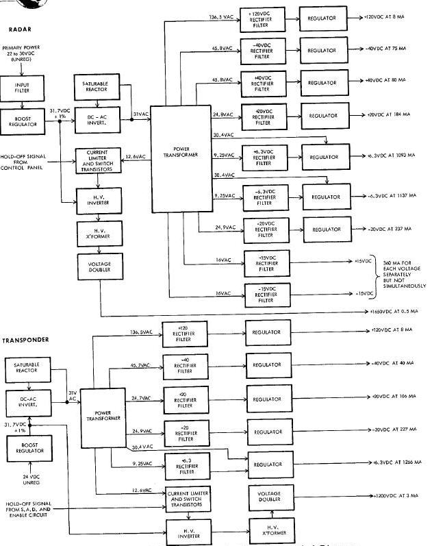
The dc to ac inverter changes the regulated 31.7 volts dc into 31
volts ac. The saturable reactor which is connected across the inverter
stabilizes the output. The inverter energizes the power transformer.
Multiple secondary windings provide all the voltages which the radar
requires. Nine of the ac output voltages are rectified and filtered. Two
of these, the plus and minus 15 volts dc, are used without regulation.
The remaining seven rectified and regulated. A short-circuit-proof
circuit is built into filtered outputs are each regulator. The
regulators of the plus 120 volts dc, the plus and minus 40 volts dc, and
the plus and minus 20 volts dc are each operated by the voltages they
regulate. The plus and minus 6.3 volts dc do not provide a high enough
voltage to operate their regulators. Therefore, additional higher
voltages from the power transformer are provided to operate these
regulators.
The transmitter requires plus 1650 volts dc plate voltage to produce the 1150-watt peek power interrogator pulse. A high-voltage power supply capable of generating this voltage is therefore provided. Although another winding could have been added to the power transformer to supply the high ac voltage needed, transients would be applied to the common transformer each time the transmitter was fired. Consequently, a separate de to ac inverter and high-voltage transformer were used. Only a 6.8 volt ac switch voltage for the high-voltage inverter was taken from the common transformer. In the standby state, the regulated 31.7 volts dc is applied to the high-voltage inverter. The switching voltage is applied through the current limiters to the high-voltage inverter, but is grounded out by the switching transistors which are conducting. The holdoff signal applied by the RADAR switch in the STBY position to the switching transistors causes them to conduct, preventing the high-voltage inverters from operating. When the pilot puts the radar in the search mode, he places the RADAR switch to ON. This action removes the holdoff voltage, and permits the 6.3 volts ac to switch the inverter on and off. As the inverter is switched, the ac voltage is generated and applied to the high-voltage transformer. The transformer steps up this voltage and applies it to a voltage doubler. The voltage doubler rectifies and doubles the ac output of the transformer, and delivers plus 1650 volts dc to the transmitter tube plate. No high-voltage regulation is required.
By comparing the block diagrams (Figure Above) of the radar and transponder power supplies, the similarities will be apparent. Both power supplies use a boost regulator, a dc to ac inverter, a power transformer, rectifier, filters, and regulators to provide plus 120, minus 40, plus and minus 20, and plus 6.3 volt dc outputs. The same high-voltage circuitry is also used.
Transponder Power Supply Differences
Certain differences, of course, between the two power supplies do
exist. The following are the differences: The transponder does not
require the plus 40, minus 6.3, and plus and minus 15 volt dc power
supplies. The current drains on individual supplies differ owing to the
peculiar needs of the two units. The transponder high-voltage power
supply is turned on when the sufficient amplitude detector triggers the
enable delay circuit and removes the hold off voltage. Less transmitter
power is used in the transponder to protect the
solid-state antenna select switch (Figure above).
AGC - Automatic Gain Control
MSG ACPT - Message Acceptance (MSG ACPT)
SAD - Sufficient Amplitude Detector (SAD)