Boost and Staging Sequence Block Diagram
Spacecraft Separation Sequence Schematic
Re-entry Control System (RC8) Activation
OAMS Lines and Lower Wires Guillotine
Upper Wire Guillotine Ignition
ELECTRONIC TIMER Circuit Breaker
BOOST CUTOFF 1 Circuit Breaker
BOOST CUTOFF 2 Circuit Breaker
ATT IND CNTL RETRO Circuit Breaker
BOOST-INSERT CONTROL 1 Circuit Breaker
B00ST-INSERT CONTROL 2 Circuit Breaker
RETRO SEQ CNTL 1 Circuit Breaker
RETR0 SEQ CRTL 2 Circuit Breaker
SEQ LIGHTS TEST (AMBER-OFF-Red & Green) Switch
SEQ LIGHTS (BRIGHT-DIM) Switch
JETT FAIRING Pushbutton Switch
IND RETRO ATT Switch-Indicator
SEP OAMS LINES Switch-Indicator
ARM AUTO RETRO Switch-indicator
Retrograde Separation Relay Panel
Spacecraft Separation Control Relay Panel
Retrograde Sequence Adapter Separate Relay Panel
Orbit Attitude and Maneuver System Squib Fire Relay Panel
Rendezvous and Recovery SECTION RELAY PANELS
Sequential System
Sequential System Diagram
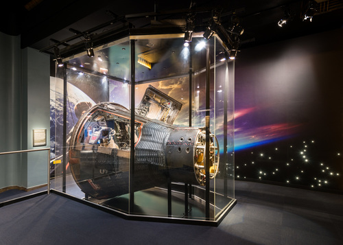
The Sequence System of Gemini Spacecraft 5, 6, and 8 through 12 comprises those controls, indicators, relays, sensors and timing devices which provide semiautomatic control of the spacecraft and/or launch vehicle during the critical control times, but which are not part of other systems. The critical times are: the time from booster engine ignition through insertion into orbit; the time to prepare to go to retrograde through post-landing; and the time to abort.
The Gemini crew does not control the spacecraft during boost through Second Stage Engine Cutoff (SSECO). The spacecraft is controlled by Radio Guidance System (RGS) and the Digital Command System (DCS), or by the Inertial Guidance System (IGS) and the on-board computer. The crew does however, monitor certain indicators to keep informed of the operation of the launch vehicle, to anticipate a crisis if one should develops, and to know if and when mission abort is mandatory. After SSECO the command pilot takes necessary action to separate the spacecraft from the launch vehicle and applies final thrust to place the spacecraft in the desired orbit.
During orbit, the Sequence System is in standby. The electronic timer, however, which is part of the Time Reference System, is counting down the time-to-go to retrograde.
At 4 minutes and 16 seconds before retrograde, (TR-256 seconds), a Sequence System relay is actuated, and several Sequence System indicators illuminate amber. These indlcators provide the crew with cues for necessary operations. Again at 30 seconds before retrograde, the crew is reminded to separate the adapter equipment and arm the automatic retrograde rocket firing circuits. The Sequence System, if properly armed, will initiate retrograde automatically. The crew redundantly initiates retrograde manually as a safety precaution. During descent, altitude indicators illuminate as cues to deploy parachutes. After splash down, the main parachute is Jettisoned, and all systems are shutdown.
Four abort modes comprise the abort sequence. They are: seat ejection (mode I); ride-it-out abort (mode I-II); modified re-entry (mode II); and normal re-entry (mode III). The mode selected for abort is related to the spacecraft altitude at the time the abort command is given.
To simplify explanation, the Sequence System is divided into eight stages. The eight stages are; pre-launch, lift-off, boost and staging, separation and Insertion, prepare-to-go to retrograde, retrograde, re-entry, and abort.
Sequential System Simplified Block Diagram
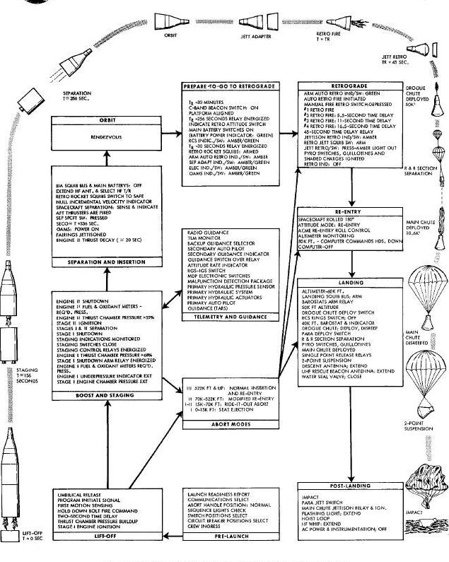
Telemetry guidance, landing and post-landing are related to but not part of the Sequence System. The simplified block diagram is explained in the following paragraphs.
Pre-launch, lift-off, boost and staging, and separation and insertion are explained first. Prepared-to-go to retrograde, retrograde, and re-entry are discussed next. Abort is discussed last.
The command pilot and the pilot ingress the Gemini cabin and take their assigned crew stations. The hatches are closed and locked. The crew checks that both D-rings are unstowed. The command pilot makes sure that the abort control handle is in the NORMAL position; the maneuver controller is stowed; the altimeter is set; and the Incremental Velocity Indicator (IVI) is zeroed. He verifies that the nine sequence indicators, the two ABORT indicator lights, the ATT RATE indicator light, the SEC GUIDANCE indicator light, both ENGINE I indicator lights, and the ENGINE II indicator light are extinguished. He places the top three rows of circuit breakers on the left switch/circult breaker panel to the closed (up) position. He places the BOOST-INSERT and RETRO ROCKET SQUIB switches in the bottom bow to ABM, and the RETRO and LANDING switches to SAFE. He tests the nine sequence indicators with the SEQ LIGHTS TEST switch. He selects switches for gyro run-up and platform alignment, and performs on-board computer checkout.
The pilot places the four MAIN BATTERIES switches and the three SQUIB BATTERIES switches to ON. Both pilots select and check their intercom and uhf communications. The remaining controls and indicators are also monitored or positioned as required. The crew verifies and reports all systems ready for launch.
When the pre-launch countdown reaches zero, the first stage engine ignition signal is given from the blockhouse. Both first stage engines begin thrust chamber pressure buildup. Both ENGINE I indicators illuminate red but extinguish in about one second. When the thrust chamber pressure of these two engines exceeds 77 percent of rated pressure, a two-second time delay is initiated in the blockhouse. If all systems remain go during this delay, the hold-down-bolt fire command is given and the launch vehicle is committed to flight. First motion sensors detect vehicle ascent one and one-half inches off the pad, and energize time-zero relays in the blockhouse and in the spacecraft. A 145-second shutdown arm time delay is initiated to prevent accidental booster engine shutdown prior to the scheduled staging time.
The umbilical release command is given, disconnecting the adapter and re-entry umbilicals. The on-board computer is switched from the guidance inhibit mode to the guidance initiate mode and enabled to accept acceleration data. The lift-off signal is also applied to the electronic timer and the event timer. The electronic timer begins to count down the time-to-go to retrograde. The event timer begins to count up the time from lift-off.
As the missile continues to climb, the crew monitor the boost sequence and ABORT Indicators. The two ENGINE I under pressure Indicators, the ATT RATE Indicator and both ABORT indicators must remain extinsulshed. The ENGINE II indicator illuminates amber. The STAGE I FUEL and OXIDIZER needles must indicate pressures within the required limits, and the L0GITUDINAL ACCELEROMETER must indicate an increasing acceleration within prescribed limits for the flight time indicated by the event timer. The pilots monitor their indicators and report via uhf link to the ground. Abort mode I prevails during the first 50 seconds of flight. Ground stations notify the pilot when abort mode I is no longer applicable and when abort mode I - II becomes applicable. Abort mode I-II is in effect during approximately the next 45 seconds of flight. At T+95 seconds, the crew receives and acknowledges changeover to abort mode II.
At T+145 seconds, when the acceleration has climbed to nearly 6g's, the first stage engine shutdown arm relays are energized. At approximately T+153 seconds, the thrust chamber pressure drops to less than 68 percent. The two ENGINE I indicators illuminate red, and the staging control relays are energized. The staging switches are closed. The stage I shutdown solenoids energize and both engines are shutdown. Acceleration drops sharply to approximately 1.5g's. The booster sequential system immediately ignites the second stage engine. The explosive bolts which unite stage 1 and stage 2 are detonated, and the stages separate. Both ENGINE I indicators are extinguished. Fuel injector pressure of the second stage engine rapidly increases above 55 percent, extinguishing the ENGINE II underpressure indicator. The LONGITUDINAL ACCELEROMETER begins to climb slowly. The crew reports the results of the staging sequence to the ground station.
Boost and Staging Sequence Block Diagram
The ENGINE II underpressure indicator, the Attitude Overrate (ATT RATE) indicator, and the two ABORT indicators must remain extinguished. The STAGE 2 FUEL and OXIDTATION needles must indicate the required pressures, and the LONGITUDINAL ACCELEROMETER must show the required increase.
At approximately T+310 seconds, the spacecraft has climbed above 522,000 feet and its velocity exceeds 80 percent of orbital velocity. The ground station notifies the crew that abort mode IIl now replaces abort mode II. Both pilots acknowledge the change of abort modes.
At T+330 seconds, the acceleration has climbed to almost 7g's, and the spacecraft has nearly reached orbital velocity and altitude. Approximately 337 seconds after lift-off, the blockhouse computer transmits the SSECO command tones via the Digital Command System to the launch vehicle. The SSECO solenoids energize SSECO occurs, thrust decays, and acceleration falls rapidly. The on-board computer begins to compute the delta-V required for insertion.
The command pilot waits 20 seconds for launch vehicle thrust to decay. Near the end of the thrust decay period, the command pilot depresses and releases the JETT FAIRING switch on the main instrument panel. This switch energizes nose fairing Jettison relays K3-13 and K3-17 and scanner cover jettison relays K3-18 and K3-19.
Spacecraft Separation Sequence Schematic
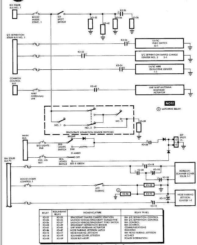
These jettison relays arm the nose fairing squibs and scanner cover squibs. The squibs detonate explosive charges, which jettison the fairing and cover.
When thrust decay is complete, the command pilot, depresses and releases the SEP SPCFT switch-indicator on the mean instrument panel shown on this Figure above. When the contacts of the SEP SPCFT switch-indicator closes, squib bus number 1 power is applied through the closed BOOST-INSERT CONT1 circuit breaker to relays K3-22, K3-24, and K3-42. (Refer to Figure 4-4). K3-22 is the spacecraft shaped charge ignition relay. K3-22 is the launch vehicle/spacecraft wire guillotine relay. K3-42 is the uhf whip antenna extend relay. Redundant contacts of the SEP SPCFT switch-indicator energize redundant relays with power from squib bus number 2. For simplicity, redundant elements are not shown.
Time delays in the relays and pyrotechnics cause the separation events to occur in the following sequence. K3-24 contacts energize the launch vehicle/spacecraft pyrotechnic switch relay K3-26. K3-26, contacts C immediately fire the pyrotechnic switch, open-circuiting the wires on the battery side of the guillotine. Next the wire guillotines are fired, severing the launch vehicle spacecraft wires at the interface. Finally the spacecraft shaped charges are ignited, breaking the structural bond between the launch vehicle and the spacecraft. The operation of all pyrotechnics mentioned in this section is explained in Pyrotechnics System.
The launch vehicle may now separate from the spacecraft, or thrust from the Orbit Attitude and Maneuver System (OAMS) may be required to effect separation. When two inches of separation exist at the interface, the spacecraft separation sensors close. The spacecraft separation sensor relay K3-28 is energized when two of the three sensor switches are actuated. Contacts A of K3-28 apply main bus power through the closed SEQ LIGHTS PWR circuit breaker and the SEQ LIGHTS BRIGHT-DIM switch to the switch-indicators. The SEP SPCFT switch-indicator illuminates green.
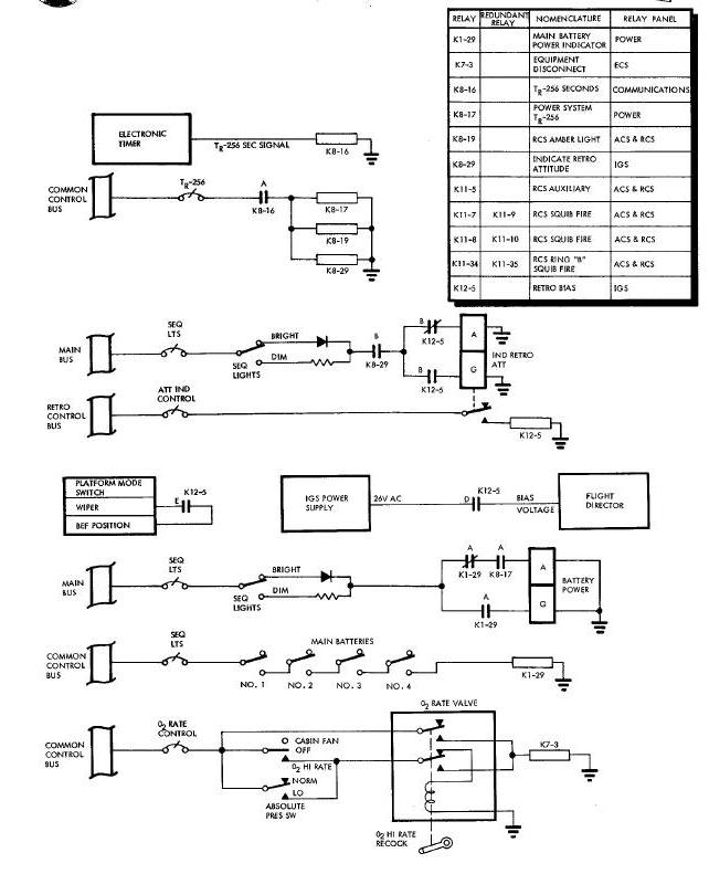
Time to Retrograde Minus 256 Seconds Sequence Diagram
The command pilot observes the delta-V required for insertion which is now displayed on the M. He fires the aft thrusters until the IVI is nu!led. The spacecraft is in the required orbit. The crew places the following switches to these positions: RETRO ROCKET SQUIB to SAFE, BOOST-INSERT SQUIB to SAFE, andn MAIN BATTERIES 1, 2, 3 and 4 to OFF. For the commlcation switches positioned at this time, refer to Pyrotechnics System Section IX.
Approximately 30 minutes before retrofire time, the crew places the C-band beacon switch to CONT and performs platform alignment procedures. Then maneuver the spacecraft to the Blunt End Forward (BEF) position.
At R-256 seconds (4 minutes and 16 seconds before retrofire time), the electronic timer energizes the TR-256 second relay K8-16. (See this Figure). The A contacts of K8-16 close and energize K8-17, K8-19 and K8-29. K8-17 is the Electrical Power System TR-256 relay, and its A contacts now close to illuminate the BTRY PWR indicator amber. K8-19 is the Re-entry Control System (RCS) amber light relay, and illuminates the RCS indicator amber. K8-29 is the indicate retrograde attitude relay, and illuminates the IND RETRO ATT indicator amber.
The amber BTRY PWR indicator reminds the pilot to turn on the main batteries by placing the four MAIN BATTERIES switches to the ON position. Relay KI-29 is energized through the ON position of the four battery switches. The BTRY PWR indicator illuminates green.
Depressing the amber IND RETRO ATT switch-indicator energizes the retrograde bias relay K12-5. K12-5 extinguishes the amber lamp and illuminates the green lamp of the indicator. K12-5 also applies the retrograde attitude bias voltage to the Flight Director Indicator (FDI), and electrically places the inertial platform in the BEF mode. The FDI needles can now be used to orient the spacecraft in this attitude.
Depresslng the RCS switch-indicator energizes the four RCS squib fire relays K11-7, F11-8, K11-9, and K11-1O. Relays K11-7 and K11-8 are energized from retrograde bus number 1 while K11-9, and K11-10 are energized from retrograde bus number 2. When any of the four RCS squib fire relays energize, the RCS auxiliary relay K11-5 is latched changing the RCS indicator from an amber to a green indication. Relays K11-7 and K11-9 both fire the package A, C, D, pressure isolation, oxidizer isolation, and fuel isolation squibs of ring B. Relays K11-8 and K11-I0 fire the package A, C, D, pressure isolation, oxidizer isolation, and fuel isolation squibs of ring A. The RCS RING A and RING B switches are now placed to ACME, and the attitude controller is operated to fire and test the RCS thrusters.
02 high rate flow is initiated after the TR-256 second sequences at the option of the crew. When the CABIN FAN switch is placed to the 02 HI RATE position, the disconnect relay K7-3 is energized. K7-3 removes power from the cabin fan power supply and the two suit power supplies, and illuminates the amber 02 HI RATE indicator.
After the TR-256 sequence, re-entry communications are selected, as discussed in the Pyortechnic System Section IX.
TIME TO RETROGRADE MINUS 3O SECONDS
Thirty seconds prior to retrograde (TR-30 seconds), the electronic timer initiates a contact closure. This closure energizes the retrograde TR-30 seconds relay K4-46, which illuminates the SEP OAMS LINE, SEP ELEC, SEP ADAPT, and ARM AUTO RETRO indicators amber. Figure below shows a logic presentation of the TR-30 second sequence. Some of the sequences shown in Figure below such as SEP OAMS LINES, SEP ELECT, and SEP ADAPT are performed redundantly. However, for simplicity only the sequences powered from retrograde squib bus number I is shown.
Time to Retrograde Minus 30 Seconds Sequence Schematic
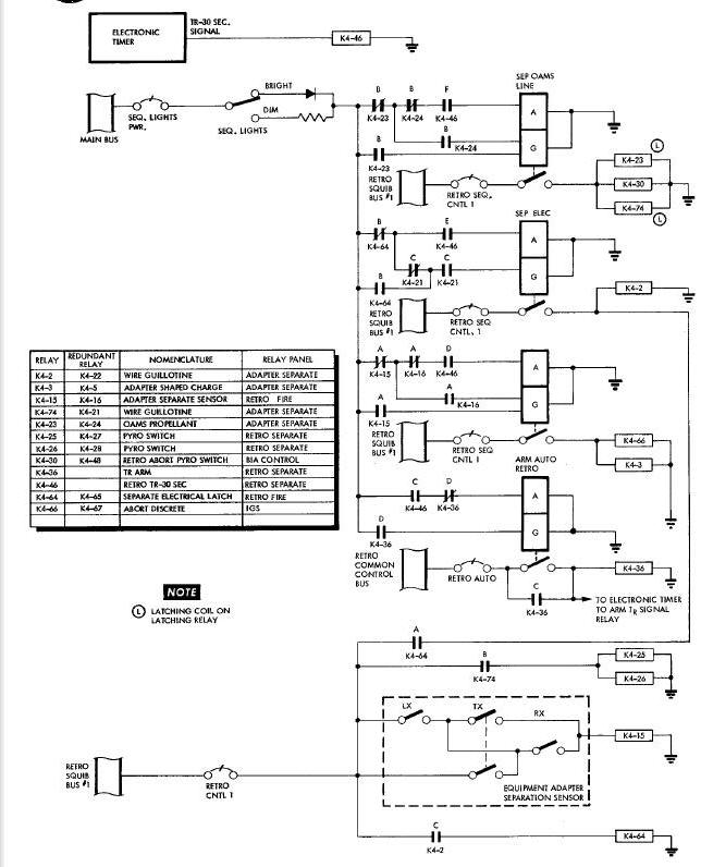
As soon as the connand pilot observes that the four indicators have illuminated amber, he depresses and releases the SEP 0AMS LINE switch-indicator. This switch closure energizes the OAMS propellant line guillotine relay K4-23 and the retrograde abort pyrotechnlc squib relay K4-30. K4-23 changes the SEP OAMS LINE indication from amber to green, fires the OAMS propellant lines guillotine igniter 1-1, and then energizes pyrotechnic switch relays K4-25 and K4-26. Relay K4-25 and K4-26 energize pyrotechnic switches B, C, D, E, F and J.
Next, the command pilot depresses and releases the SEP ELEC switch-indicator which energizes wire guillotine relay K4-2. K4-2 ignites wire guillotine C, D and E and energizes the separate electrical latch relay K4-64. When K4-64 energizes, the SEP ELEC switch-indicator chemges from amber to green. Then, the command pilot initiates the equipment adapter separation sequence by depressing and releasing the SEP ADAPT switch-indicator. Closure of the SEP ADAPT switch energizes the adapter shaped charge relay K4-3 and abort discrete relay K4-66. K4-3 detonates shaped charge igniter 2-1 and 3-1. The adapter equipment section separates, and separation is sensed by three toggle sensor switches. The switches close when the physical separation is one and one half inches. The closure of any two switches energizes the adapter separate sensor relay K4-15. K4-15 changes the SEP ADAPT switch-indicator from amber to green. The green SEP ADAPT light informs the crew that the adapter equipment section has been Jettisoned from the spacecraft. K4-66 sends the abort transfer discrete to the on-board computer.
Lastly, the command pilot depresses and releases the ARM AUTO RETRO switch-indicator. The ARM AUTO RETRO switch latches the arm relay KM-36. This relay changes the indication from amber to green and arms the electronic timer for the TR relay contact closure. The four RETR0 ROCKET SQUIB switches are now moved to the ARM position.
A logic diagram of the retrograde sequence is shown in Figure 4-7. As discussed previously, whenever a sequence is initiated from retrograde squib bus number 1, there is an identical redundant sequence initiated from retrograde squib bus number 2. The retrograde sequence is initiated by the TR signal from the electronic timer. The redundant sequence is initiated manually by the crew.
At Retrograde (TR), the electronic timer latches the TR signal relay K4-34. The TR signal relay in the latched condition energizes the retrorocket automatic fire relay K4-7. K4-34 also energizes the 45-second time delay relay K4-4, initiates a 5.5-seconds, 11.0-seconds, and a 16.5-second time delay, and deactivates the IGS platform free mode. The retrorocket automatic fire relay redundemtly fires retrorocket number 1 from retrograde squib bus number 1 and number 2. At the end of the 5.5-second time delay, the retrorocket automatic fire relay K4-9 is energized. K4-9 ignites retrorocket number 3 from retrograde squib bus number 1 and nunber 2. Retrorocket number 2 is redundantly ignited from retrograde squib as number 1 and number 2 when the retrorocket automatic fire relay K4-31 energizes at the end of the 3.0-second time delay. Retrorocket automatic fire relay K4-13 is energized at the end of the 16.5-second time delay. K4-23 redundantly fires retrorocket number 4 from retrograde squib bus number i and number 2.
In order to assure retrograde rocket ignition, the command pilot initiates manual retrograde ignition by depressing and releasing the MAN FIRE RETRO switch-indicator approximately one second after automatic retrofire initiation. The MAN FIRE RETRO switch latches the manual retrograde latch relay K4-37, energizes retrorocket manual fire relay K4-8, and initiates the 45-second time delay relay K4-6. This switch also initiates the 5.5-second, 11-second and 16.5-second time delays. The 5.5, 11 and 16.5-second time delays energize retrorocket manual fire relays K4-10, K4-12 and K4-14 respectively, which in turn fire retrorockets number 3, number 2, and number 4 respectively. Retrorocket number 1 is fired by K4-8. As in automatic retrorocket fire, each retrorocket is fired from retrograde squib bus number 1 and number 2. Twenty-two seconds after retrofire is initiated, the last retrorocket ceases firing. The command pilot moves the JETT RETRO SQUIB ARM switch on the left switch circuit breaker panel from SAFE to ARM. Forty-five seconds after retrograde ignition, K4-4 or K4-6 energizes and illuminates the JETT RETRO lamp on the main instrument panel.
As soon as the command pilot observes the JETT RETRO indicator is amber, he despresses and releases this switch-indicator. The switch energizes the retrograde separate shaped charge relay K4-17, the retrograde bias off relay K4-62, and the horizon scanner heads Jettison relay K4-38. Relay K4-I7 fires retrograde adapter shaped charge igniter 1-1, 2-1, and 3-1 and pyrotechnic switch H-I. Relay K4-62 latches the re-entry roll display relay K12-6 removing roll mix interlock from the flight director controller. Kh-62 also resets two latch relays: the retrograde bias relay K12-5 and the indicate retrograde attitude relay K8-29. Relay K8-29 extinguishes the IND RETRO ATT indicator. K4-18 fires horizon scanner cover squib 1-1 if it was not fired previously during the boost phase. K4-38 ignites the horizon scanner head sequencing through an 80 millisecond pyrotechnic time delay and Jettisons the scanner head. The firing of pyrotechnic switch H-1 extinguishes the SEP ELEC, SEP ADAPT, SEP OAMS, ARM ADTO RETRO and JETT RLTRO indicators.
On spacecraft 6 and 8 through 12, the JETT RETRO switch also energizes latch release relay K4-69 through the B contacts of the nose fairing Jettison latch relay K3-86. K4-69 fires the release igniters of docking latches 1, 2 and 3 to Jettison them. K4-69 also energizes the index bar Jettison and latch door release relay K4-73. K4-73 fires three latch door cover release igniters. These igniters release the latch doors which cover the ports left by the Jettison docking latches. K4-73 also Jettisons the docking index bar. If the bar was not extended previously, it is first extended and then Jettisoned. These functions are not a part of the retrograde sequence during an abort if the abort occurs prior to nose fairing Jettison.
After the retrograde adapter and horizon scanner
heads have been Jettisoned, the command pilot places the RETR0 PWR
and RETRO JETT squib switches to SAFE. Using the attitude controller and
the FDI needles, he rolls the spacecraft 180 degrees so that the horizon
is visible in the upper portion of his cabin window He changes the
ATTITUDE CONTROL mode select switch on the main instrument panel from
PULSE to RATE CMD (RE-ENTER). The command pilot uses attitude control
and maneuvering electronics and the attitude controller to control the
roll attitude during approximately the next 10 minutes in which the
altitude diminishes to 400,000 feet. As this altitude the FDI roll
needles start to move, the computer START light illuminates and the
computer begins to calculate the point of impact. The command pilot
changes the ATTITUDE C0NTROL mode selector switch from RATE CMD
(RE-ENT) to RE-ENT. The computer now computes the roll attitude for
optimum re-entry lift and also automatically controls the roll
attitude. During approximately the next 10 minutes, the altitude
decreases to 100,000 feet. At this altitude, the altimeter indicator
becomes to come off the peg. At 80,000 feet, the computer commands the
spacecraft to assume the best attitude for drogue parachute deployment.
Then the command pilot places all guidance and electronic switches to
OFF.
An abort ls an unscheduled termination of the spacecraft mission. An abort may be initiated at any time during the spacecraft mission. In all cases the actual abort sequence has to be initiated by the crew after an abort command has been received. An abort indication consists of illumination of the ABORT indicators located on the command pilot and pilot's panels. The ABORT indicator may be illuminated by three different methods. During pre-launch prior to umbilical disconnect, the ABORT indicator may be illuminated from the blockhouse via hardline through the launch vehicle tail plug connector. After umbilical release, the ABORT indicator may be illuminated by ground command to the spacecraft via a channel of the DCS or by ground command to the launch vehicle to shutdown the booster.
The abort sequence is part of the Sequence System. The abort sequence comprises the abort indicators, controls, relays, and pyrotechnics. The part of the abort sequence which the crew make use of is determined by the abort mode in effect at the time when the abort command is received or the decision to abort is made.
Abort Modes Simplified Block Diagram
The abort mode to be used at any time during the mission is determined by calculations made on the ground and depends on the altitude and velocity attained by the spacecraft. The critical abort altitudes are 15,000 feet, 75,000 feet, and 522,000 feet. The spacecraft reaches 15,000 feet approximately 50 seconds after lift-off, 75,000 feet approximately 100 seconds after lift-off, and 522,000 feet approximately 310 seconds after lift-off. Below 15,000 feet, seat ejection (mode I) is used. Between 15,000 and 75,000 feet, ride-lt-out abort (mode I-II) is used. Between 75,000 and 522,000 feet, modified re-entry (mode II) is used. Above 522,000 feet normal re-entry (mode III) is used, except that the spacecraft electronic timer does not illuminate the sequential indicators amber when the time to press them occurs, unless the timer is updated by ground command. The Figure above presents a simplified block diagram of the abort sequences in each of the three modes.
When an abort becomes necessary during pre-launch, it is accomplished by using abort mode I. The abort command is given from the blockhouse by hardline through the launch vehicle tail plug connector. The command lights both ABORT indicators on the command pilot and pilot's panels. When the pilots see this display, they immediately pull the D-rings attached to their ejection seats. When one D-ring is pulled, both ejection systems are energized. One-half seconds later, the hatches are open, and one-half second after that the seats have been ejected. Sensors detect the ejection of the seats and notify the blockhouse that the pilots are out of the spacecraft. One-quarter second after the seats are ejected, a sustainer rocket under each seat is fired, which extends the distance between the pilots add the launch vehicle. Then a pyrotechnic ignites and separates the ejection seat from the pilots. Two seconds after sustainer ignition, the main parachutes have opened and the pilots are lowered safely to the ground. For illustrations and fuller descriptions of the equipment used for seat ejection abort, refer to Cabin Interior Section III of this manual.
After normal llft-off, and before the Gemini-Titan reaches an altitude of 15,000 feet, an abort condition could develop. The crew monitor their booster indicators so that they are aware at all times of the manner in which the flight is proceeding. Booster operation data is telemetered to the ground for analysis and interpretation. The range safety officer, the booster systems engineer, the flight director, or the flight dynamics officer, who are on the ground, any decide that danger is imminent and an abort mandatory.
A channel of the DCS is used to send the abort command to the spacecraft and ground commands are sent to the launch vehicle to shutdown the booster engines. Then the engine shutdown tones are received, the destruct switches of the launch vehicle are armed. The two ENGINE I indicators and both ABORT indicators illuminate red. The command pilot and pilot evaluate these displays and pull the D-rings. The hatches open and the pilots in their seats are ejected, Refer to Cabin Interior Section III for a description of the remainder of this sequence.
Abort mode I - II is the ride-it-out abort mode. It is effective at altitudes between 15,000 and 75,000 feet approximately 50 seconds to 100 seconds after lift-off. Abort mode I - II is used when a mode I abort is inadvisable and when a delay to permit entry into the mode II conditions is impractical. The crew however has the option to eject or to ride-it-out depending upon their assessment of the abort conditions. Therefore the D-rings are not stowed during the I - II mode.
Abort mode I - II begins during stage I boost approximately 50 seconds after liftoff. If an abort condition develops, and the crew elect to ride it out, the command pilot moves the abort control handle from NORMAL to SHUTDOWN. He waits 5 seconds for booster thrust to decay, then moves the handle from SHUTD0WN to ABORT.
The retrograde abort relays and the retrograde abort interlock relays are energized. These relays arm the buses needed for abort action. The retrograde common control bus is armed from the common control bus. Retrograde squib buses number 1 and number 2 are armed from OAMS squib buses number 1 and number 2. On spacecraft 5 only, spacecraft separation squib buses number 1 and number 2 are armed from Boost Insert Abort (BIA) squib buses number 1 and number 2. Two parallel circuits are used for redundancy. This arming of buses by means of relays eliminates the motion of throwing the switch ordinarily required to arm the buses. Then, in rapid succession wire gillotine relays, pyrotechnic switch relays, and shaped charge igniter relays are energized. The relays ignite the pyrotechnics at the equipment adapter/retrograde adapter mating line, and the vehicles separate. Then, the four retrorockets are salvo fired and the spacecraft thrusts away from the launch vehicle.
If the abort altitude is between 15,000 and 25,000 feet the retrograde adapter is Jettisoned 7 seconds after retrorocket salvo fire is initiated. If the abort altitude is between 25,000 and 75,000 feet, the retrograde adapter is Jettisoned 45 seconds after salvo fire.
After retrograde adapter Jettison, the spacecraft is maneuvered to the re-entry attitude. If the abort altltude is above 40,000 feet, the drogue parachute is deployed at 40,000 feet, and the main parachute at 10,600 feet. If the drogue parachute fails or has not been deployed before the spacecraft descents to 10,600 feet, the emergency main parachute switch is used to deploy the main parachute. If one of the two first stage engines should fall and the launch vehicle is above 40,000 feet, the pilots may elect to remain with the spacecraft until the operating engine has boosted them to 75,000 feet. At this altitude, abort mode I - II becomes inapplicable.
Abort mode II becomes effective above 75,000 feet. At approximately 100 seconds after lift-off on a normal mission, the launch vehicle has boosted the spacecraft to an altitude of 75,000 feet. Ground station computers calculate the time for changeover from abort mode I - II to abort mode II. The ground station notifies the crew via the uhf communications link of the change to abort mode II. Both the command pilot and pilot acknowledge the change via the same link, and stow the ejection seat handles (D-ring). Initiation of abort mode I above 75,000 feet could be disastrous.
Abort mode II begines during stage 1 boost before booster engine cutoff and ends during stage 2 boost before second stage engine cutoff. The crew continues to monitor the booster indicators. If they should notice an abort situation developing, they analyze it. The decision to abort may be theirs or it may come from the ground. If a ground station sends the command to abort, both ABORT indicators illuminate red. In abort mode II, the command pilot must act. He moves the abort handle to the SHOTDOWN position. The operatlng engine is cutoff. Since launch vehicle destruct is iminent and escape from the fireball is urgent, he moves the ABORT handle to ABORT. The spacecraft is separated from the launch vehicle at the equipment adapter/retrograde adapter mating line. The retrorockets, armed by four RETRO ROCKET SQUIB switches during pre-launch checkoff, are salvo fired, propelling the spacecraft away from the launch vehicle.
Since orbital velocity could not have been reached below 522,000 feet, the spacecraft immediately begins a re-entry trajectory. The spacecraft is maneuvered to the retrograde blunt end forward attitude, the retrograde section is jettisoned, and normal landing procedures are initiated.
At approximately 310 seconds after lift-off, the launch vehicle reaches the altitude of 522,000 feet and a velocity of approximately 21,000 feet per second. The ground station commands a change from abort mode II to abort mode II via the uhf link.
If an abort after this time should become necessary, the ABORT indicators would be illuminated red. The command pilot responds and moves the ABORT handle to the SHUTDOWN position. The shutdown command is thus given to the second stage engine. The ABORT handle remains in the SHUTD0WN position. The command pilot then presses the SEP SPCFT swltch-indicator on the main instrument panel. This switch fires the shaped charges and severs the wiring at the launch vehicle/spacecraft mating line as described earlier. 0AMS thrust is applied to put distance between the second stage and the spacecraft. The crew perform the TR-256 seconds and the TR-30 seconds procedures, using the main instrument panel switch-indicators. After retrofire has been initiated manually, normal re-entry, landing, and postlanding procedures are followed.
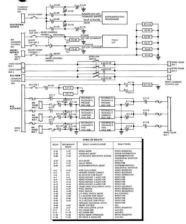
The abort sequence described herein occurs during abort modes II and I - II. The description covers the series of events which the abort control handle and Figure Below shows the electrical circuits which cause the abort sequence to occur. Figure Below includes the switches, circuit breakers, buses, relays, and pyrotechnic igniters. A table of the Figure Below gives the names, reference designations and relay panel locations of the relays and redundant relays of the abort sequence. The redundant relays, their buses, fuses, and squibs (with a few exceptions) are not shown, since the circuitry and end results are identical with those shown. The omission is made to maintain clarity and simplicity.
Abort mode I, the seat ejection mode, is not covered here. The events of this mode are discussed in the Cabin Interior Section III of this Manual.
Abort mode III is executed by performing a launch vehicle engine shutdown, a spacecraft separation sequence and a retrograde sequence. Separation and retrograde in abort mode III differs from normal separation and retrograde in that the abort sequence is performed without cues from the indicators on the main instrument panel. The electrical circuits however are identical with those shown in the shutdown sequence (See Above Figure), the spacecraft separation (See Above Figure), the TR-256 seconds sequence (Figure Above), the TR-30 seconds sequence (See Above Figure).
When the command pilot moves the abort control handle to SHUTDOWN, the SHUTDOWN switch is closed. BIA common control bus power is applied to the launch vehicle engine shutdown signal relays K3-28 and K3-49. This power is also applied to the engine shutdown relays in the Titan Launch Vehicle. The operating engine(s) are cut off. As K3-48 and K3-49 energize, common control bus power is applied through their B contacts to the spacecraft instrumentation programmer. The programmer encodes the voltage from this bus as the booster cutoff command signal for telemetry transmission to the ground tracking station.
Then the command pilots moves the abort control handle to ABORT, numerous relays are energized, as shown of See Figure Above. However five of these relays are key relays in that they control the principal abort operations. These operations are: (1) telemetry of the abort action to the ground; (2) arming of the retrograde buses; (3) activation of the RCS; (4) separation of the spacecraft from the launch vehicle; and (5) salvo firing of the retro rockets.
The relays which control those operations are: (1) the instrumentation abort relay, K3-92; (2) the squib bus abort relay K3-38; (3) the Attitude Control System abort relay K3-59; (4) the retrograde abort relay K3-36; and (5) the salvo retrograde relay K3-71.
When the instrumentation abort relay K3-92 is energized by the abort switch, its B contacts connect common control bus power to the spacecraft instrumentation programmer. The programmer encodes this signal as the pilot actuated abort signal for telemetry transmission to the ground.
Abort, if it occurs, requires that power for the circuits used in the retrograde phase of the mission become immediately available. When the abort switch is closed, squib bus power is applied to K3-38. K3-38 arms the retrograde squib buses 1 and 2 and the retrograde common control bus.
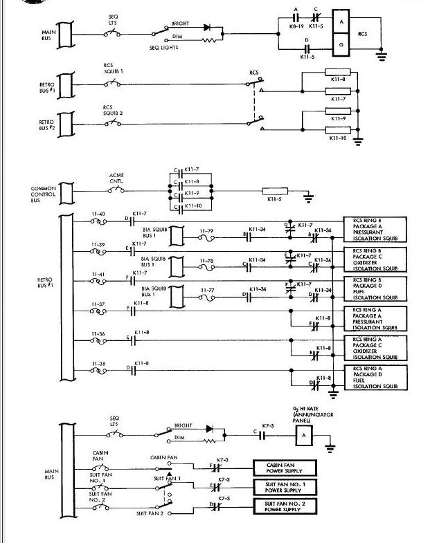
Re-entry Control System (RCS) Activation
Re-entry immediately and automatically follows an abort. Re-entry requires the use of the RCS for control of the spacecraft during this phase. Hence the RCS is activated. Activation involves opening and pressurizing the RCS fuel and oxidizer lines. This is done by firing the squibs of the fuel, oxidizer, and pressurant packages.
In operation, the abort switch applies BIA squib
bus power to the Attitude Control System abort relay K3-59. K3-59
applies retrograde squib bus power to RCS (ring A) squib fire relay
KII-8 and the RCS (ring B) squib fire relay KII-7. KII-8 applies
retrograde squib bus power to package A, C, and D igniters of RCS ring
A. The squibs thus fired open the ring A fuel and oxidizer lines and
pressurize them.
KII-7 applies retrograde squib bus power to similar igniter of RCS ring
B with similar results.
The B contact of F13-7 and KII-8 energize the retrograde abort interlock relay KII-22. KII-25, contact A initiates the station 7.70 separation sequence.
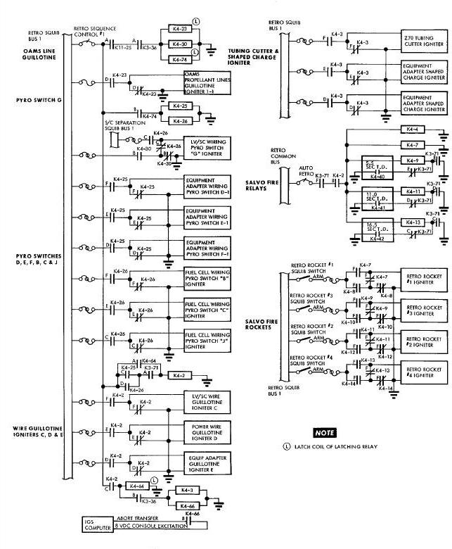
OAMS Lines and Lower Wires Guillotine
Since the retrorockets are to be fired in the abort modes controlled by the abort switch, the spacecraft must separate from the launch vehicle at station Z7O. Z7O is on the mating line between the spacecraft and the equipment adapter section. To make separation complete, the OAMS propellant lines which cross this station must be sealed and guillotined.
The abort switch energizes the retrograde abort relay K3-36 which arms K4-23, the OAMS lines guillotine latch relay; K4-30, the retrograde abort pyrotechnic switch relay; and K4-74, the wire guillotine relay. When 11-25 is energized, it energizes. K4-23, K4-30, and K4-74. The D contacts of K4-23 apply power to the OAMS propellant lines guillotine igniter. The guillotine now seals and cuts the lines. Pyrotechnic switch G fires, opening the launch vehicle/spacecraft interface circuits. The lower wire gundles are guillotinged. The first step toward launch vehicle/spacecraft separation has been taken.
The second step in launch vehicle/spacecraft separation is the removal of power from the hot wires crossing station Z7O. These wires like the propellant lines, must also be guillotined, and the guillotine blade could cause a short circuit of the spacecraft power. Pyrotechnic switches B, C, D, E, F, G and J must be operated to remove power from the wires to be guillotined.
K3-36 and K11-25 apply power to launch vehicle/spacecraft pyrotechnic switch abort relay K4-30 and to wire guillotine latch relay K4-74, initiating pyrotechnic switch ignition. K4-3O applies power to launch veihicle/spacecraft wiring pyrotechnic switch G igniter, opening pyrotechnic switch G. K4-74 energizes pyrotechnic switch relays K4-25 and K4-26. K4-25 ignites equipment adapter pyrotechnic switches D, E end F. K4-26 ignites fuel cell wiring pyrotechnic switch B, C and S. With the operation of the pyrotechnic switches, the second step in launch vehicle/spacecraft separation has been taken.
Upper Wire Guillotine Ignition
The third step in launch vehicle/spacecraft separation is the cutting of the upper wires that cross station Z70. This is accomplished by actuating the wire guillotines. Three wire guillotines igniters must be fired: the launch vehicle/spacecraft wire guillotine igniter C, the power wire guillotine igniter D, and equipment adapter wire guillotine Igniter E.
When K4-25 and K4-26 energize, they apply power through the A contacts of K3-TI to wire guillotine relay K4-2. K4-2 fires the wire guillotine igniters C, D and Z cutting the station Z7O wires.
K4-2, contact C energizes the separate electrical latch relay K4-64, the adapter shaped charge relay K4-3 and the abort discrete relay K4-66. K4-66, contact A latches K4-2 in the energized position. K4-66 changes the computer from the ascent mode to the re-entry mode and enables the computer to accept re-entry data and solve the re-entry problem. K4-3 prepares the way for the fourth step in the separation of the launch vehicle from the spacecraft.
Tubing and Structural Bond Cutting
The fourth and final step is to sever the adapter skin at station Z70 and break the launch vehicle to spacecraft structural bond.
When K4-2 causes K4-3, the adapter shaped charge relay to energize, K4-3 fires the Z70 tubing cutter igniter and the equipment adapter shaped charge igniters. The pyrotechnics complete the task of launch vehicle/spacecraft separation.
The retrorockets are salvo fired at the same time that the tubing and structural bond is cut. To salvo fire the retrorockets, power must be applied simultaneously to the retrorocket automatic fire relays and thus to the retrorockets. Therefore the 5.5, 11.0, and 16.5 second time delay relays must be bypassed. Contacts C, D, and E of K3-71 bypass the time delay relays. When K4-2 energizes, retrograde common bus power simultaneously energizes the retrorocket automatic fire relays K4-7, K4-9, K4-11 and K4-13. As these relays energize, retrograde squib bus power is applied to the igniters of retrorockets 1, 3, 2 and 4. Salvo burn lasts approximately 5.5 seconds.
When the retrorocket automatic fire relays are energized by K4-2, the 45-second time delay relay K4-4 is also energized. When K4-4 energizes after 45 seconds, it illuminates the JETT RETRO switch indicator as shown on This Figure. The JETT RETRO switch-indicator is then pressed, and the retrograde section is Jettisoned in a mode II abort. However, in a mode I - II abort when the altitude is between 15,000 and 25,000 feet, the switch-indicator is pressed seven seconds after the retrorockets begin firing. After the retrograde section has been Jettisoned, normal re-entry and landing procedures are initiated.
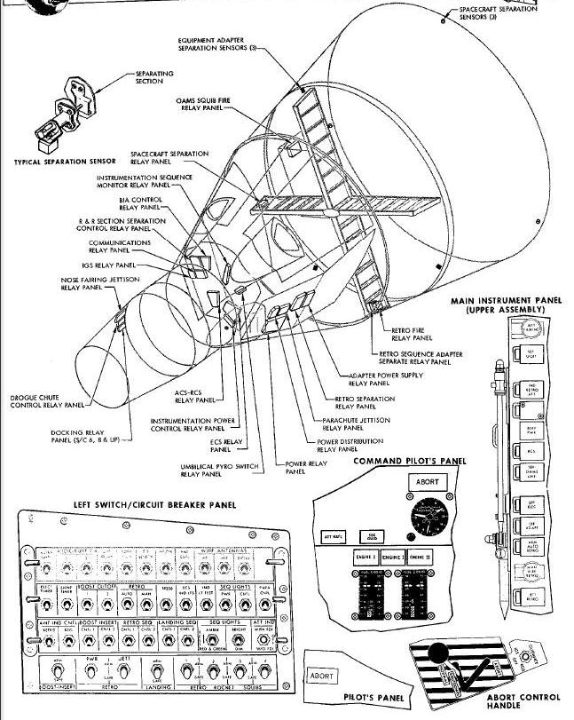
The Sequence System as shown in Figure 4-1 comprises the following units; Left switch/circuit breaker panel, consisting of three rows of circuit breakers and one row of switches.
Boost and staging indicators, consisting of seven lights and three meters on the top of the command pilot and pilot's panels.
Sequence controls, consisting of two pushbutton switches, eight switch-indicators, and one indicator are located on the left side of the main instrument panel.
Re-entry switches and indicators, consisting of four switches on the main instrument panel center console and one switch, two lights, and two meters on the command pilot 's panel.
Abort controls, consisting of two D-rings on the ejection seats and one abort control handle on the left side of the cabin.
Relay panels, consisting of four relay panels in the re-entry module and four in the equipment adapter and retrograde sections, and two In the rendezvous and recovery section.
Separation sensing devices, consisting of three each in the equipment adapter section and the retrograde section.
The components of the Sequence System are described below:
Left Switch/Circuit Breaker Panel
The switches and circuit breakers on the left switch and circuit breaker panel perform Important functions in the operation of the Sequence System. The top row of circuit breakers however pertain largely to communications. The second row of circuit breakers perform functions related to the operation of the Sequence System. Their functions are as follows:
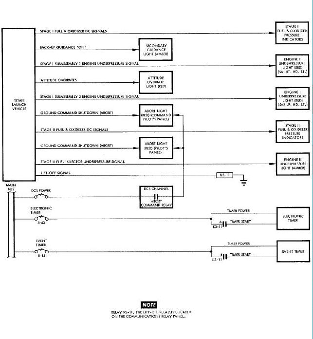
ELECTRONIC TIMER Circuit Breaker
The electronic timer circuit breaker CB8-15 applies main bus power through contact A of lift-off relay K3-11 to start the electronic timer when the lift-off signal energizes the K3-11. The timer begins counting the time-to-go to retrograde.
The event timer circuit breaker CB8-14 applies main bus power through contact B of lift-off relay K3-11 to start the event timer when the lift-off signal energizes KS-11. The event counter counts the time since lift-off occurred.
BOOST CUTOFF 1 Circuit Breaker
The boost cutoff 1 circuit breaker CB3-8 applies BIA common control bus power to the booster shutdown switch on the abort control and to the secondary guidance (RGS-IGS) switch. This circuit breaker arms the booster shutdown circuit and the secondary guidance manual swltch-over circuit.
BOOST CUTOFF 2 Circuit Breaker
The boost cutoff 2 circuit breaker CB3-21 applies BIA common control bus power redundantly to the booster shutdown switch, and supplies power for the second stage engine cutoff signal input to the computer.
The retrograde fire automatic circuit breaker CB4-1 applies retrograde common control bus power to the ARM AUTO RETRO switch. It provides power to salvo fire the retrorockets during the abort sequence. If CB4-1 is not closed, the electronic timer TR contact closure will not automatically fire the retrorockets.
The retrograde manual circuit breaker CB4-2 provides retrograde common control bus power for manually firing the retrorockets, and salvo firing the retrorockets with the abort control handle.
The retrograde minus 256 seconds circuit breaker CB8-16 applies common control bus power to relay contacts in the electronic timer and contacts of the TR-256 second relay. CB8-16 enables the TR-256 second signal to illuminate amber the IND RETRO ATT, BTRT PWR, and RCS indicators on the main instrument panel.
SEQ LIGHTS POWER Circuit Breaker
The sequence lights power circuit breaker CB6-1 applies main bus power to the sequence light BRIGHT-DIM switch and to open contacts on the barostat switch arm relay and the message acceptance pulse relay.
SEQ LIGHTS C0NTR0L Circuit Breaker
The sequence lights control circuit breaker CBI-13 applies common control bus power through the four MAIN BATTERIES switches to relay K1-29. When the main battery power indicator relay KI-29 is energized, the BTRY PWR indicator on the main instrument panel is illuminated green.
The third row of circuit breakers on the left switch/circuit breaker panel perform functions related to the Sequential System. The functions are the following:
ATT IND CNTL RETRO Circuit Breaker
The attitude indicate control retrograde circuit breaker CB12-7 applies retrograde common control bus power to the IND RETRO ATT switch-indicator and to contacts of retrograde bias off relays K4-62 and K4-63. Power from CB12-7 energizes retrograde bias relay K12-5 when the JETT EETRO indicator is pressed.
BOOST-INSERT CONTROL 1 Circuit Breaker
The boost-insert control 1 circuit breaker CB3-1 provides BYA squib bus number 1 power to initiate the abort sequence with the abort control handle, Jettison the nose fairing and scanner cover, separate the spacecraft from the launch vehicle, sense launch vehicle/spacecraft separation, extend the uhf and diplexer whip antennas, and initiate several experiments.
B00ST-INSERT CONTROL 2 Circuit Breaker
The boost-insert control 2 circuit breaker CB3-11 connects BIA SQUIB BUS number 2 power redundantly to the same switches to which CB3-1 connects power.
RETRO SEQ CNTL 1 Circuit Breaker
The retrograde sequence control 1 circuit breaker CB4-3 connects the retrograde Squib bus number 1 to the SEP OAMS LINES switch-indicator, the SEP ADAPT switch-indicator, the SEP ELEC switch-indicator, and the JETT RETR0 switch-indicator on the main instrument panel. It also arms the abort discrete relays and the equipment adapter separation sensor switches and relays.
RETR0 SEQ CRTL 2 Circuit Breaker
The retrograde sequence control 2 circuit breaker CB4-28 connects the retrograde squib bus number 2 redundantly to the same switches to which the retrograde sequence control 1 circuit breaker connects power and arms the same circuits.
SEQ LIGHTS TEST (AMBER-OFF-Red & Green) Switch
The sequence lights test switch connects main bus power to all amber-colored sequence lights and to all lights on the annunciator panel in the AMRED position and to all red or green sequence lights in the RED & GREEN position.
SEQ LIGHTS (BRIGHT-DIM) Switch
The sequence light bright-dim switch is a single-pole, double-throw toggle switch. It connects the main bus through a diode to all sequence light circuits in the LIGHT position. It connects the bus through a resistor to the same circuits in the DIM position.
The fourth row on the left switch/circuit breaker panel contains eight switches. These switches arm or safety the various squib buses used by the Sequential System. Their functions are as follows.
BOOST-INSERT (ARM-SAFE) Switch
The boost-insert squib bus arm-safe switch is a four pole, double throw toggle switch. In the ARM position, this switch arms the BIA squib buses I and 2 and the BIA Common control bus. These buses arm the SEP SPCFT switch-indicator, the BOOST CUTOFF 1 and 2 circuit breakers, the BOOST INSERT CONTROL I and 2 circuit breakers, and the relay contacts which fire the nose fairing Jettison, scanner cover Jettison, OAMS activate, RCS activate, spacecraft separate, guillotine and pyrotechnics.
The retrograde power squib bus arm-safe switch is a four-pole, double-throw switch. In the ARM position, it arms retrograde squib bus 1 and 2 and the retrograde common control bus. Thru these buses it arms the RETRO JETT ARM-SAFE switch the RETRO ROCKET SQUIB AUTO-SAFE 1, 2, 3, and 4 switches, the ATT IND CNTL RETRO, RETR0 SEQ 1 and 2, and RETRO0 AUTO and MAN circuit breakers on the left switch/circuit breaker panel, and the RCS SQUIB 1 and 2 circuit breakers on the overhead Switch/circuit breaker panel.
The retrograde Jettison squib bus arm-safe switch is a two-pole double-throw toggle switch. In the ARM position, it arms retrograde Jettison squib buses number 1 and number 2. From these buses, the retrograde Jettison relays set the power to fire the retrograde adapter shaped charges and retrograde pyrotechnic switch H.
RETRO ROCKET SQUIB 1, 2, 3, 4 (ARM-SAFE) Switches
The four retrograde rocket squib arm switches apply the voltages which ignite the four retrofire rockets to open contacts of the retro rocket automatic and manual fire relays. In the safe position of these four switches, the ignition voltage is removed from the relays. When both the RETRO POWER squib arm switch and the four RETRO ROCKET SQUIB arm switches ere placed to the ARM position, the OAMS squib buses 1 and 2 are connected redundantly to the retrorocket fire relays.
B00ST-INSERT-ABORT CORTROLS AND INDICATORS
Seven indicators, three meters and four controls are provided for the boost insert-abort phase of the spacecraft mission.
The two ENGINE 1 indicators are provided on the command pilot's panel to indicate thrust chaimber underpressure of the first stage booster engines. Each indicator illuminates red when the thrust chamber pressure of the engine is 68 percent of rated pressure or less. Both indicators illuminate red at stage 1 ignition but extinguished 0.91 to 1.25 seconds later as the pressure increases above 68 percent. Both indicators illuminated at booster engine cut-off and extinguish quickly at staging.
The ENGINE II indicator on the command pilot's panel illuminates amber to indicate the fuel injector underpressure (or off) condition of the second stage engine. The critical pressure for engine 2 is 55 percent of rated value. The indicator illuminates when the first stage engine is ignited and stays amber through first stage boost. Approximately one second after both ENGINE I indicators extinguish, the ENGINE II indicator also extinguishes, indicating normal staging and engine II fuel injector pressure build up.
The attitude rate indicator on the command pilot's panel indicates an evaluation of the launch vehicle attitude rates during the boost phase. The indicator is extinguishes if the attitude rates remain within acceptable limits but illuminates red if the rates exceed these limits.
The secondary guidance indicator on the command pilot's panel indicates which guidance system is in operation. The indicator is extinguished to indicate that primary guidance is being used. The indicator illuminates amber to indicate that secondary guidance has been selected.
Two ABORT indicators are provided, one for each pilot. Both indicators illuminate red when the abort command is transmitted. When the ABORT indicator is illuminated, immediate and appropriate action is imperative. The indicator signals the crew to initiate immediately the abort mode appropriate for the altitude and velocity of the spacecraft. These modes are described under Sequence System Operation. During the boost phases the crew has been retained via the uhf communications link of the abort mode in effect.
The stage 1 fuel end oxidizer meters on the command pilot's panel enable the crew to monitor the current status and progress of the boost phase, and to anticipate an abort condition if one should develop. These meters indicate the gas pressures in psia of the stage 1 fuel and oxidizer tanks. Dual indicator needles are provided for redundancy. The range of the stage 1 meters is 35 to 5 psia. A time versus-pressure scale near the bottom of the meter shows the minimum required pressure at 20, 40, and 60 seconds after lift-off. Critical fuel tank pressure is indicated by a shaded column at the low end of the scale. After staging with no signals applied, the meters indicate maximum psla.
The stage 2 fuel and oxidizer meters on the
command pilot's panel indicate stage 2 fuel and oxidizer tank pressure
over a 70 to i0 psla range. Redundant pointers are used. Critical fuel
tank pressures are indicated by a shaded column at the low end of the
scale. The S-flag at the 30-psia mark indicates the minimum acceptable
stored pressure in the tank before pressurization. After spacecraft
separation, the meters indicate maximum psia.
The accelerometer on the command pilot's panel indicates the rate in g's at which the launch vehicle engines are changing the velocity of the spacecraft. The range of the accelerometer is minus 6g's to 16g's. The meter has positive and negative memory pointers. The accelerometer enables the crew to monitor the effectiveness of the engines. It is a secondary indicator of staging.
The guidance switch above the abort control handle permits the command pilot to manually change from primary guidance to secondary backup guidance. When back-up guidance has been selected either manually or automatically during stage I boost and the ground station determines that primary guidance is feasible during stage 2 boost, primary guidance can be selected again by momentarily placing the guidance switch to the RGS position.
A D-ring Is provided on the ejection seat of each pilot. These rings are pulled to initiate mode I abort at altitude below 70,000 feet. Refer to Section III of thls volume for the location and operation of these devices.
SEQUENCE CORTROLS AND INDICATORS
The switches, indicators, and switches-indicators on the main instrument panel center console have the following nomenclature, place in the mission sequence, and functions.
JETT FAIRING Pushbutton Switch
The Jettison fairing switch is used at the end of second phase engine thrust decay, by the command pilot to Jettison the nose fairing, and the horizon scanner head cover.
The separate spacecraft switch-indicator is used
in the separation-insertion phase of the sequence. The command pilot
presses the switch-indicator approximately 20 seconds after second stage
engine cutoff when the IVI displays the delta-V required for insertion.
Pressing the switch-indicator causes several things to happen.
Primarily, it detonates pyrotechnic devices which separate the
spacecraft from the launch vehicle. Secondarily, it extends the uhf and
diplexer antennas and readies the acquisition aid beacon for use. As the
spacecraft moves away from the launch vehicle, separation sensors close
and energize the spacecraft separation relays.
The relays illuminate the Indicator green.
IND RETRO ATT Switch-Indicator
The Indicate retrograde attitude
switch-indicator is illuminated amber when the electronics timer
energizes the TR-256 second relay. The amber light cues the crew to
press the switch-indicator at this time. When pressured, a bias voltage
is placed on the pitch needle of the FDI, and the inertial platform is
electrically placed in the REF mode. When released the ember light is
extinguished and a green
light is illuminated.
The battery power indicator illuminated amber by
the TR-256 second relay. The amber light cues the pilot to place the
MAIN BATTERIES switch to ON, and the fuel cell switch or ADABTER
BATTERIES switch to OFF. This change must be made because
the adapter section will be Jettisoned at retrograde. When all of the
main battery switches are on, the Indicator changes from amber to green.
The RCS indicator Is lllumlnated amber by the TR-256 second relay. The amber light cues the command pilot to activate the RCS by firing the fuel, oxidizer, and pressurant isolation squibs. Pressing the switch-indicator energizes relays which fire the squibs. The indicator changes from amber to green, indicating that the RCS has been activate.
SEP OAMS LINES Switch-Indicator
The separate OAMS lines indicator is illuminated amber by the TR-256
second relay is the prepare-to-go to retrograde phase. The amber light
cues the crew to seal and sever the OAMS lines before jettisoning the
adapter. Pressing the switch indicator energizes relays which ignite the
pyrotechnics used to seal and sever the lines. The relays also fire
pyrotechnic switches and wire guillotines
severing some of the adapter-retrograde mating line wiring. The
indicator changes from amber to green.
The separate electrical indicator is also illuminated amber by the T2-256 second relay. The amber light cues the crew to sever all the wiring at the retrograde/adapter mating line. Pressing the switch-indicator energizes the wire guillotine relay. The pyrotechnics are detonated and the wiring is cut. The indicator changes from amber to green to indicate that electrical separation has been accomplished.
The separate adapter indicator is illuminated amber by the R-256 second relay. The amber light cues the crew to Jettison the adapter equipment section. Pressing the switch-indicator causes the adapter shaped charge and the Z7O tubing cutter pyrotechnic to be detonated, and the adapter section severed. Separation of the adapter section is sensed by the equipment adapter separation sensors. Two closed sensors energize the sensor relay and change the indicator from amber to green.
ARM AUTO RETRO Switch-indicator
The arm automatic retrofire indicator is illuminated amber by the TR-3O second relay. The amber light cues the crew to arm the automatic retrofire circuits so that when the electronic timer closes the TR contacts at TR time, the retrorockets will fire automatically. Pressing the switch-indicator completes the patch from the retrograde common control bus to the timer TR contact, and also energizes the TR arm relay. The relay changes the light from amber to green. Contact closure at TR time energizes the TR signal relay. The signal relay energizes the 45-second time delay relay, fires the retro rockets at 5.5 second intervals, and puts the platform in the free mode.
MAN FIRE RETR0 Pushbutton Switch
The manual fire retrorockets switch connects the retrograde common control bus to the manual retrograde latch relay. Contacts of this relay energizes the 45-second time delay relay, fire the retrorockets at 5.5-second intervals, and place the platform in the free mode operation.
The Jettison retrograde adapter indicator is
illuminated amber by the 45-second time delay relay 45 seconds after
retrofire begins. The amber light cues the crew to jettison the
retrograde adapter. Pressing the indicator ignites pyrotechnic switch H
and other pyrotechnic devices which disconnect and guillotine the wires
at the retrograde adapter section/re-entry vehicle mating line. It
fires the shaped charges which sever the retrograde adapter section from
the re-entry vehicle. It energizes the Horizon Sensor System scanner
head jettison relays which fire the jettison squibs and Jettison the
scanner head. It removes the retrograde attitude signals applied to the
flight director needles at TR-256 seconds. It switches the FDI roll
channel to the mix mode for re-entry. Finally
by igniting pyrotechnic switch H it extinguishes the IND RETRO ATT, SEP
OAMS LINE, SEP ELEC, HEP ADAPT and ARM AUTO RETRO green indicators and
the JETT RETRO amber indicator.
Ten Sequence System relay panels are installed in Gemini Spacecraft 5, 6, and 8 through 12. Four relay panels are located in the re-entry vehicle, three in the retrograde section, one in the equipment section, and two in the rendezvous and recovery section. See Figure Above. The following Sequence System relay panels are in the re-entry module.
The boost-insert-abort control relay panel contains six relays to perform spacecraft separation indicator control and launch vehicle/spacecraft pyrotechnic switch firing.
Retrograde Separation Relay Panel
The necessary functions required for adapter retrograde section separation are performed by the fourteen relays of the retrograde separation relay panel. The relays perform such functions as pyrotechnic switch and shaped charge ignition, TR-3O second indication, automatic IGS free mode selection, and arming of the contacts of the Time Reference System.
ACS Scanner and RCS Squib Fire Relay Panel
Re-entry Control System squib firing, scanner cover and scanner heads jettison, abort interlock RCS amber light actuation, and RCS ring B squib firing test prior to launch are provided by the sixteen relays of the attitude control system scanner and RCS squib fire relay panel.
Umbilical Pyrotechnic Switch Relay Panel
The umbilical pyrotechnic switch relay panel contains two relays which apply landing squib bus 1 and 2 power to re-entry umbilical wiring pyrotechnic switch.
The retrograde section contains the following three relay panels which control spacecraft separation, retrofire, and equipment section separation. The equipment section contains the Orbit Attitude Maneuver System squib fire relay panel.
Spacecraft Separation Control Relay Panel
The spacecraft separation control relay panel contains six relays to perform the following functions: shaped charge ignition, and launch vehicle/spacecraft guillotine firing.
The retrofire relay panel has twenty relays. These relays control the automatic, anual and salvo firing of the retro rockets, and time the 5.5-second firing sequence.
Retrograde Sequence Adapter Separate Relay Panel
The retrograde sequence adapter separate relay panel contains twelve relays. The relays are used for equipment adapter shaped charge ignition, propellant line guillotine, electrical wire guillotine, and retrograde abort.
Orbit Attitude and Maneuver System Squib Fire Relay Panel
The 0AMS squib fire relay panel contains six relays for firing the OAMS squibs and controlling the regulator valves.
Rendezvous and Recovery SECTION RELAY PANELS
The Rendezvous and Recovery section contains two Sequence System relay panels : the nose fairing Jettison relay panel, and the docking relay panel.
Nose Fairing Jettison Relay Panel
The nose fairing Jettison relay panel contains two relays which control the Jettisoning of the nose fairing.
The docking relay panel has eleven relays which extend the docking index bar, illuminate the MSG ACPT light, effect emergency release of the docking latches, release and Jettison the locking latches at retrograde, Jettison the index bar, and cover the docking latch ports.
The Sequence System contains two sets of separation sensors. These are the launch vehicle/spacecraft separation sensors and the equipment adapter/re-entry vehicle separation sensors. Figure above shows their configuration and location. Figure above shows how the launch vehicle/spacecraft separation sensors operate. Figure above shows how the equipment section/re-entry vehicle separation sensors operate. Separation sensors are toggle switches which are normally open before separation is initiated. The separating structure will close the sensors as it moves away from the spacecraft re-entry module. The closure of any two of a set of three sensors is sufficient to sense and indicate separation.
Blunt End Forward (BEF)
Boost Insert Abort (BIA)
Digital Command System (DCS)
Inertial Guidance System (IGS)
Incremental Velocity Indicator (IVI)
Orbit Attitude and Maneuver System (OAMS)
Radio Guidance System (RGS)
Re-entry Control System (RCS)
Retrograde (TR)
Second Stage Engine Cutoff (SSECO)
4 minutes and 16 seconds before retrograde, (TR-256 seconds)