Time Reference System
Time Reference System Functional Diagram
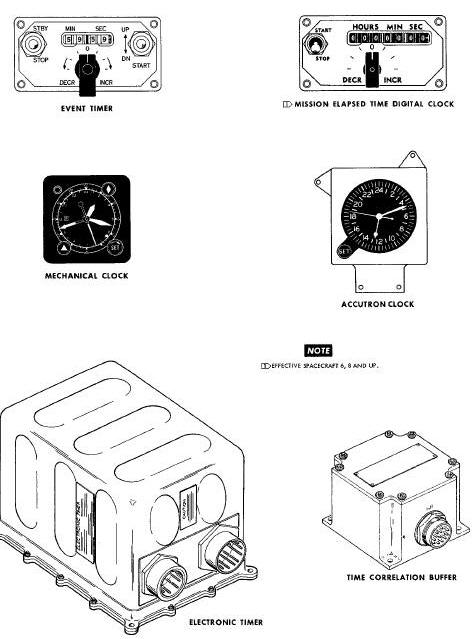
Time Reference System Components
Electronic Timer Functional Block Diagram
Frequency Division and Time Decoding Schematic Diagram
Time Decoding Gates Inputs and Outputs A
Time Decoding Gates Inputs and Outputs B
Magnetic Core Operation Diagram
Data Word Flow-Counting Process
Storage Register Schematic Diagram
MISSION ELAPSED TIME DIGITAL CLOCK
Mission Elapsed Digital Clock Functional Diagram
Event Timer Functional Diagram
SYSTEM DESCRIPTION
The Time Reference System (TRS) provides the facilities for performing
all timing functions aboard the spacecraft. The system is comprised of
an electronic timer, a time correlation buffer, a mission elapsed time
digital clock, an event timer, an Accutron clock and a mechanical clock.
The event timer, mission elapsed time digital clock, Accutron clock and
mechanical clock are all mounted on the spacecraft instrument panels.
The electronic timer is located in the area behind the center instrument
panel and the time correlation buffer is located in back of the pilot's
seat.
The electronic timer provides (1) an accurate countdown of Time-To-Go to retrofire (TTG to TR) and Time-To-Go to equipment reset (TTG to TX). (2) time correlation for the PCM data system (Instrumentation) and the bio-med tape recorders, and (3) a record of Elapsed Time (ET) from lift-off.
The Time Correlation Buffer (TCB), conditions certain Output signals from the electronic timer, making them compatible with bio-med and voice tape recorders. Provision is included to supply buffered signals for Department of Defense (DOD) experiments if required.
The mission elapsed time digital clock (on spacecraft 6 through 12) provides a digital indication of elapsed time from lift-off. The digital clock counts pulses from the electronic timer and is therefore started and stopped by operation of the electronic timer.
The event timer provides the facilities for timing various short-term functions aboard the spacecraft. It is also started at lift-off to provide the pilots with a visual display of ET during the ascent phase of the mission. In case the electronic timer should fail, the event timer may serve as a back-up method of timing out TR.
The Accutron clock provides an indication of Greenwich Mean Time (GMT) for the command pilot. The clock is powered by an internal battery and is independent of external power or signals.
The mechanical clock provides the pilot with an indication of GMT and the calendar date. In addition, it has a stopwatch capability. The stopwatch provides an emergency method of performing the functions of the event timer.
Four components of the Time Reference System (electronic timer, event timer, Accutron clock and mechanical clock) function independently of each other. The two timing components (mission elapsed time digital clock and time conciliation buffer) are dependent on output signals from the electronic timer. A functional diagram of the Time Reference System is provided below.
Time Reference System Functional Diagram
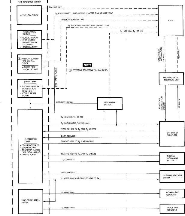
The electronic timer, mission elapsed time
digital clock, Accutron clock and the time-of-day portion of the
mechanical clock operate continuously, during the spacecraft mission.
The mechanical clock and Accutron clock are started during the
pre-launch period. The electronic timer starts operating upon receipt of
a remote start signal from the Sequential System at the time of
lift-off.
If the lift-off signal is not received from the Sequential System, the electronic timer can be started by actuation of the START-UP switch on the event timer. The mission elapsed time digital clock and time correlation buffer start operating upon receipt of output signals from the electronic timer.
During the mission, the event timer, Accutron clock and the stopwatch portion of the mechanical clock can be started and stopped manually, at the discretion of the crew. At lift-off, however, the event timer is started by a remote signal from the Sequential System.
At the time of lift-off, the electronic timer
begins its processes of counting up elasped time and counting down TTG
to TR and TTG to TX. ET is counted up from zero to a maximum of
approximately 2 days. The retrofire and equipment reset functions are
counted down to zero from certain values of time which are written into
the timer prior to lift-off. The timer is capable of counting TG to TR
from
a maximum of 2 days and to equipment reset from a maximum of two hours.
The TTG to TR data contained by the timer may be updated at any time during the mission by insertion of new data. Updating may be accomplished either by a ground station, through the Digital Command System (DCS), or by the crew, via the Manual Data Insertion Unit (MDIU) and the digital computer. To prevent inadvertent, premature countdown of TR as a result of equilment failure or personnel error during update, the timer will not accept any new time-to-go of less than 128 seconds duration. Upon receipt of new data of less than the inhibit time mentioned above, the timer will cause itself to be loaded with a time in excess of two weeks.
The TTG to TX function of the timer serves to reset certain equipment which operates while the spacecraft is passing over a ground 1 station equipped with telemetry. As the spacecraft comes within range, the ground station inserts, via the DCS, a TTG to TX in the timer. Then, as the spacecraft moves out of the range of the ground station, the TG to TX reaches zero, and the equipment is automatically reset. If the ground station is unable to insert the time data, it may be done by the crew, using the MDIU and digital computer. Information from the electronic timer is not continuously displayed; however, confirmation of satisfactory operation may be made by the readout of data through use of the digital computer MDIU display readout capability.
Note: The mission elapsed time digital clock counts pulses from the electronic timer and, assuming no loss of pulses, will indicate the elapsed time recorded in the electronic timer. The digital clock does not, however, read out the elapsed time word from the electronic timer.
The electronic timer is approximately 6
inches x 8 3/4 inches x 5 1/2 inches and weighs about ten pounds. It has
two external connectors for interface with its associated systems. The
enclosure for the unit is! sealed to keep out moisture but is not
pressurized. The timer utilizes a modular Construction, containing eight
modules which are wired directly into the enclosure. The modules are:
(1) crystal oscillator, (2) timing assembly, (3) register control
assembly, (4) memory control assembly, (5) memory assembly, (6) driver
assembly, (7) relay assembly, and (8) power supply. Printed circuit
boards and solid-state components are used in all modules except the
crystal oscillator.
Time Reference System Components
The electronic timer is basically an electronic binary counter. It performs the counting operation for each of its functions (ET, TTG to TX, and TTG to TX) by an add/subtract program which is repeated every 1/8 seconds. (Figure below). In each repetition of the counting operation, a binary word, representing ET or a TTG, is modified to represent a new amount of time. Magnetic core storage registers are used to store or remember the binary words between counting cycles. A storage register is provided for each of the three timer functions and another is provided for use as a buffer register for data transfer between the timer and the digital computer.
Electronic Timer Functional Block Diagram
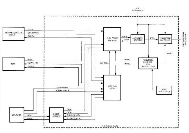
A crystal controlled oscillator is used as a
frequency standard for developing the timing pulses necessary for the
operation of the timer. The type of oscillator provides the high degrees
of accuracy required for the timer whose operations take place in very
small fractions of a second. The oscillator is coupled to a series of
toggle flip flops whose outputs provide the actual timing pulses for the
timer operation.
The electronic timer utilizes a 32-word time program. That is, each 1/8 second of time is further divided into 32-word times. Each word time is divided into 32 bit times, and each bit time is divided into 32 S pulses times. S pulses are the shortest pulses used in the timer operation and are 3.8 microseconds long. One bit time is equal to 122 microseconds and one word time 3.9 milliseconds.
It is pulses of these durations, and their multiples, which are produced by the toggle flip flops in the timing module.
Timer operation is initiated when a 28 vdc start
signal is received from either the spacecraft Sequential System or the
event timer. The signal from the Sequential System is transmitted to the
electronic timer, automatically, at liftoff; the one from the event
timer is generated when the UP/DN toggle switch on the face of the unit
is placed in the UP position. Receipt of a signal from either source
causes the set side of the clock-start relay to be actuated. Until
lift-off, the relay is held in the reset position by a clock-hold signal
from the AGE via the spacecraft umbilical. This is done to assure that
tht timer will not be started prematurely and will be at zero at the
time of lift-off. Actuation of the clockstart relay causes a positive
control signal to be applied to a gate in the timing module. This gate
allows the output of the crystal controlled oscillator to be coupled to
the countdown flip flops.
The countdown and time decoding operations take place primarily in the timing module. When timer operation is initiated, the 1.048576 megacycle output of the crystal controlled oscillator is coupled to the first of a series of 17 toggle flip flops. Twelve of the flip flops are contained in the timing module and five in the register control module. The flip flops form a frequency dividing network, each stage of which produces one square wave output pulse for every two input pulses. The output frequency of the final stage in the series is eight pulses per second.
Frequency Division and Time Decoding Schematic Diagram
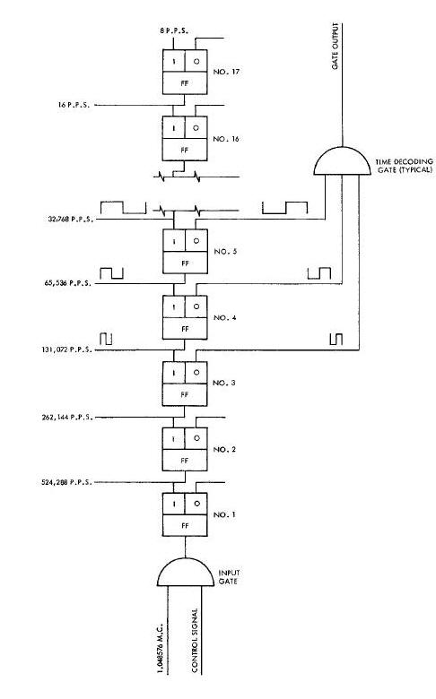
Outputs of all but the first two stages of the
countdown circuitry are utilized to develop the timing pulses necessary
for timer operations. Output pulses from either the 1 or the 0 side of
an individual flip flop may be used; however, the polarity of the pulses
from one side will be 180° out of phase with those from the other side.
Pulses from the flip flop outputs are supplied, in certain
combinations, to gate circuits in the time decoding section. Each gate
circuit receives several input pulse trains and produces output pulses
which are usable for the timer circuitry (Figure below).
Time Decoding Gates Inputs and Outputs A
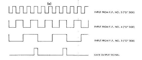
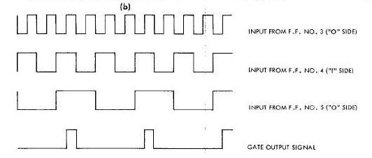
Basically, a gate will produce output
pulses which will have the pulse width of the narrowest input pulses and
the frequency of the input pulse train with the widest pulses. If the
polarity of one input is reversed, the time at which the output pulse
occurs, will change
F, (Figure B below).
Time Decoding Gates Inputs and Outputs B
Two complete modules are required to encompass all of the circuitry necessary to perform the control functions in the electronic timer The register control module primarily controls the transfer of data into and out of the timer. The memory control module directly controls the operatiom of the magnetic storage registers in the memory module.
The register control module supplies the control
signals which are required to perform the operations directly associated
with the transfer of time data. It utilizes the various command and
clock signals from the other spacecraft systems to produce its control
signals. The control signals are then supplied to the appropriate
circuitry to: (1) receive a new binary data word (as in the updating
process), (2) initiate the shifting operations of the proper storage
registers to write in or read out the desired time data (ET, TX, or TX),
and (3) supply data, read out of the storage registers, to the proper
timer output termlnal(s) to be transferred to the system requesting it.
The memory control module directly controls the operation of the magnetic storage registers and performs the arithmetic computations of the counting process. Inputs from the timing and register control modules are utilized to develop the shift and transfer output pulses for shifting data words into and out of the storage registers. These pulses are developed separately for each register.
Both control modules are made up of rather complex and overlapping networks of logic circuitry. The memory control module also employs shift current generators and transfer switches, as output stages, to develop the required power capabilities.
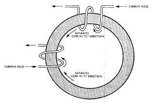
The magnetic storage register to ET, TX, and TX are used to store or remember binary words of time data. These data words may be shifted out of their respective registers, as required, for the counting operations and for transfer to other spacecraft systems. The transfer of data into and out of a storage register is accomplished, serially, with the Least Significant Bit (LSB) first.
A storage register is comprised of a series of magnetic memory cores, each of which is capable of storing one binary bit of time data. This capability is based upon the characteristic of a magnetic core to saturate in one of two directions when a current pulse is applied to one of its windings below. Saturation in one direction represents a binary I and indicates the presence of a data bit. Saturation in the other direction represents a binary 0 and indicates the absence of data bit. The storage registers for ET and TTG to TR each contain 24 magnetic cores and the register for TTG to TX contains 16. Therefore, a binary word for ET or TR consists of 24 bits, while a word for TX consists of 16 bits.
Magnetic Core Operation Diagram
The use of the binary system for time
representation permits the storage of data which can represent an amount
of time as small as 1/8 second and as large as 24 days. Each data bit in
a binary data word represents one individual increment of time. In
looking at the flow diagram in this
Figure
, the 24
sections of the storage register represent its individual cores. The
data bit which represents
the smallest time increment (1/8 second) is stored in core number 24. It
is referred to as the LSB in the data word.
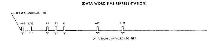
Data Word Flow-Counting Process
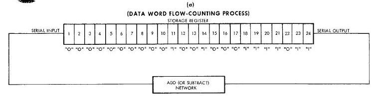
Core number 23, then would store the next bit (representing 1/4 of a second) of the data word. The sequence continues, with core number 22 representing I/2 second, back through core number 1 with each successive core representing a time increment twice that of the preceding one. By adding together the increments of time represented by all of the cores, the total time capacity of the register can be determined. Thus, it is found that the ET and TR registers have capacities of approximately 24 days and the TX register, approximately two hours. Conversion of a data word to its representative may be accomplished by totaling the increments of time represented by the bit positions of the word where binary ones are present. For the data word shown in Figure below the representative time is 583 3/8 seconds.
The process of shifting a data word into or out of a storage register is controlled by the occurrence of the shift and transfer pulses and by the condition of a control gate preceding each register and its write-in amplifier. The shift and transfer pulses from the control section are supplied to a storage register whenever a data word is to be written in or read out. These pulses occur once each bit time for a duration of one word time. The actual flow of data into a storage register is controlled by a logic gate preceding the write-in amplifier for each register (Figure Below). The count enable input of the gate will have a continuously positive voltage applies after liftoff has occurred. The write-in pulse input will have a positive pulse applied for 7.6m microseconds during eachbit time (122 microseconds). These two inputs control the gate. The result is that a positive data pulse may pass through the gate only during a 7.6 microsecond period during each bit time.
Storage Register Schematic Diagram
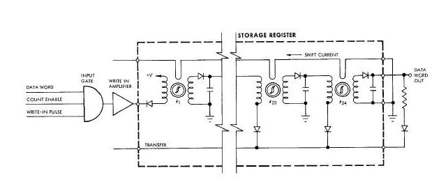
When a binary data word is to be written into a storage register, its individual bits appear at the input of core number i as a series of current pulses. When the first current pulse (representing 1/8 second) of the word flows through the input winding of core number 1, the core is saturated in the binary 1 direction. It remains in this condition until a current pulse flows through the shift winding of the core. The shift pulse causes the flux of the core to collapse and reform, switching the core back to the 0 condition. When this occurs, a voltage is developed across the output winding of the core and the temporary storage capacitor is charged through the winding from the core and the temporary winding from the diode end. When the shift pulse decays and a ground potential is placed on the transfer line, the capacitor discharges through the input winding of the next core, setting it to the binary 1 condition. Whenever a bit position of the incoming data word does not contain a pulse, core number 1 is not switched to I. As a result, its shift pulse causes no change of flux; no voltage is developed across the output and the capacitor is not charged or discharged. Hence, the next core is not set to the 1 condition. Because the shift pulses are applied to all the cores in a register, simultaneously, it is assured that each one is set to the 0 condition before the transfer pulse (also applied to all cores, simultaneously) allows the storage capacitors to discharge. When a complete word has been written into the register, the cores which are in the binary 1 condition contain the binary data bits.
Reading a data word out of a storage register involves basically the same processes as writing one in.
The data bits shift from left to right, with the bit in core number 24 leaving the register first. An additional bit is shifted out of the register with each repetition of the shifting process.
The counting operation for each of the timer
functions consists of reading a binary data word out of a storage
register, cycling it through an arithmetic network, and writing it back
into the register. (Refer to
this Figure).
The operation is
completed in one word time and is repeated every i/8 second. In the
process, the time representation of the word is changed by an increment
of 1/8 second.
The read and write portions of the counting operation take place concurrently. As the first data bit is shifted out of a register, the remaining bits shift one core 1to the right, leaving core number I vacant. Before the next shift operation takes place, the bit which has been shifted out of the register is cycled, instantaneously, through the arithmetic circuitry and inserted back into core number 1. The process is the same for each bit of the word. Thus, when the last bit of the original word is shifted out of the register, the first bit of the new one shifts into core number 24. The last bit then cycles through the arithmetic circuitry and enters core number 1, completing the counting operation.
In the arithmetic portion of the counting process, the output of the elapsed time register is supplied to an add circuit and those from the TR and TX registers to separate subtract circuits. Both types of circuits are made up of combinations of logic and switching circuits. Their operation is quite similar, the main difference being in their logic programs.
The add process for the ET consists of adding a binary I to the first bit position (the LSB) of the word coming into the add circuit. If there is already a 1 in that bit position, the 1 is carried to the next bit position. The carry operation continues until the 1 reaches an open bit position.
When the first bit of a data word read out of the
ET register is a binary 0 the add circuit produces a positive output
signal. The positive signal is then inverted by the write-in amplifier
and supplied to the input of the storage register. With a negative input
to the register, a binary 1 is written into core number 1 as the first
bit of the new word. Thus, the first bit of the word has been changed
from a binary 0 to a binary 1 adding 1/8 seconds to the representative
time of the word. The remaining bits are written back into the
register just as they were read out.
When a binary i is read out the ET register as the first bit of a data word, the output of the add circuit will be negative. Upon inversion by the write-in amplifier, the signal will be positive. A positive signal at the register input causes a binary 0 to be written into the first core. If the subsequent consecutive, data bits are also binary l's, the output of the add circuit remains negative, causing binary l's to be written into the register. Upon receipt of the first binary 0 in the data word from the register, the output of the add circuit becomes positive, causing a binary i to be written back into the register for that bit position. For example, if the first five bits of the word being read out of the register are binary l's (representing a total of 3 7/8 seconds of ET) and the next one is a binary O, then the first five bits of the new word will be binary O's; and the sixth will be a binary 1. A binary i in the sixth bit position represents and ET of four seconds. The remaining bits of the data word, again, are inserted back into the register Just as they were read out.
Although the circuitry of a subtract network is much the same as that of an add network, the operation is different because of the subtract logic. If the LSB of a word coming into a subtract network is a binary 1, the output for that bit position will be negative, causing a binary O to be written back into register. In this case, the 1/8 second has now been subtracted, and the balance of the word will remain the same. If the LSB of the incoming word is a binary 0 the output of the subtract network will become positive, allowing a binary 1 to be written into the register. The output of the subtract circuitry will remain positive until the first binary I enters the circuitry. When this occurs, the output becomes negative and causes a binary 0 to be written into the register. The rest of the word is then written back into the register Just as it came out.
Binary words of time data are transferred into and out of the electronic timer by several different methods. Data words received from the ground station, via the DCS, are inserted directly into their respective storage registers in the timer. Data from the guidance system computer, however, is transferred into the buffer register of the timer and then shifted into the proper storage register.
The same process is involved in the transfer of data from the timer to the computer: a word is shifted out of its storage register into the buffer register and then transferred to the computer. Data transfer from the timer to the Instrumentation System is accomplished by shifting the desired data out of its register to a pulse transformer. The output of the transformer is coupled to a storage register in the instrumentation System.
The following is a list of the inputs and outputs of the electronic timer together with a brief description of each:
-
INPUTS
-
(a) A continuous 28 vdc signal from the spacecraft Sequential System at lift-off to start the recording of ET and countdown of TR and TX.
-
(b) A 28 volt emergency start signal from the event timer to initiate the electronic timer operation in the event that the lift-off signal
is not received from the Sequential System. The signal would be crew-ground co-ordinated and would be initiated by actuation of
the event timer UP/DN switch to UP. -
(c) A Read, rite command signal from the digital computer to direct the timer as to which function is to be accomplished.
-
(d) A _ to TR address si_ual from the digital computer to update or readout TTG to TR.
-
(e) A _ to Tx address signal from the digital computer to enter a TTG to Tx.
-
(f) An elapsed time address signal from the digital computer to readout ET.
-
(g) Twenty-four clock pulses from the digital computer to accomplish data transfer. (25 pulses for data transfer out of the electronic
timer.) -
(h) Write data for update of TTG to TX, or TTG to Tx from the digital computer. Twenty-four data bits will be forwarded serially, LSB first.
-
(i) A TTG to TR ready signal from the DCS to command update of TTG to TR
-
(J) A TTG to Tx ready signal from the DCS to co,and entry of a TTG to TX.
-
(k) Serial data from the DCS to update TTG to TR, or TTG to Tx. Twenty-four data bits will be forwarded serially, LSB first. Clocking is provided by the electronic timer.
-
(l) TTG to TR readout signals from the Instrumentation System.
-
(m) An elapsed time readout signal from the Instrumentation System.
-
(n) An AGE/count inhibit signal from ground based equipment, via the spacecraft umbilical, to keep the elapsed time register at zero
time prior to launch. -
(o) A clock hold signal from ground based equipment, via the spacecraft umbilical, to prevent the timer from operating prior to
launch. -
(p) An event relay reset signal from ground based equipment, via the spacecraft umbilical.
-
q) An event relay check signal from ground based equipment, via the spacecraft umbilical.
-
OUTPUTS
-
(a) A contact closure at TR for the digital computer.
-
(b) A contact closure at TR (Continuous) for the Sequential System.
-
(c) A contact closure at TX for the DCS.
-
(d) Read data to the digital computer for ET or TTG to TR . Data bits are forwarded serially, LSB first.
-
(e) Signal power (12 +-10 volts) to the DCS and Instrumentation System.
-
(f) Twenty-four clock pulses to the DCS to accomplish data transfer.
-
(g) Twenty-four clock pulses to the Instrumentation System to accomplish data transfer.
-
(h) Serial data to the Instrumentation System for readout of ET or TTG to TR. Data bits are forwarded serially, LSB first.
-
(i) A contact closure from TR-256 seconds to TR for the Sequential System.
-
(J) A contact closure from TR-30 seconds to TR for the Sequential System.
-
(k) An input power monitor signal to ground based equipment via the spacecraft umbilical.
The Time Correlation Buffer (TCB) supplies the
time correlation signals for the blo-medical and voice tape recorder.
Serial data and data clock output from the electronic timer is applied
to the TCB input. Serial data contains 24 elapsed time words, and extra
elapsed time word and a time-to-go to retrograde word. The TCB selects
the extra elapsed time word end modifies the word format to make it
compatible wlth the tape recorder frequency responses. Information to
the recorder is updated once every 2.4 seconds and has the same
resolution (1/8 second) as the electronic timer.
The dimensions of the TCB (see Figure) are 2.77 x 3.75 x B.80 inches and the weight is approximately B.O pounds. The TCB contains magnetic shift registers, a 100 kc eatable multivibrator, a power supply and logic circuitry. One 19 pin connector provides both input end output connections.
The operation of the TCB is dependent on signals from the Instrumentation System and the electronic timer. In response to request pulses from the Instrumentation System, the electronic timer provides elapsed time and tlme-to-go to retrograde words to both the Instrumentation System and the TCB. The elapsed time word is supplied every I00 milliseconds. In addition, once every 2.4 seconds it provides an extra elapsed time word and i00 milliseconds later it provides a tlme-to-go to retrograde word.
The TCB requires elapsed time information only, therefore, the tlme-to-go to retrograde word is rejected. The tape recorders, due to their response times, are not capable of recording time data every I00 milliseconds end for this reason only the extra elapsed time word is accepted by the TCB. The remaining 24 elapsed time words and the time-to-go to retrograde word are rejected by logic circuitry in the TCB. Rejection of unused words is based on their time relationship to other words.
The TCB contains three 8-bit magnetic shift
registers in which the 24-bit extra elapsed time word is loaded once
every 2.4 seconds. The TCB then shifts out bits at the rate of one every
100 milliseconds. The shift rate is based on data clock pulses from the
electronic timer. The first data clock pulse in a word causes the TCB to
shift out one blt of the data and the other 23 data clock pulses are
disregarded.
Each bit that is shifted out of the shift
register is stretched in time and coded to make it compatible with tape
recorder response times. The output to the biomedical recorder is one
positive pulse for a binary O and two positive pulses for a binary 1.
The most significant bit has two additional pulses to distinguish it
from the other 23 bits in the word. Data is shifted out of the TCB in a
least
significant bit first and most significant or marker bit last.
The output to the voice tape recorder is the same basic format as for the biomedical recorders. However, to make it compatible with the higher frequency response characteristics of the voice tape recorder, each output pulse is chopped into two pulses, doubling the frequency.
All input and output signals are coupled through isolation transformers providing complete DC isolation.
MISSION ELAPSED TIME DIGITAL CLOCK
The mission elapsed time digital clock (used on spacecraft 6 through 12) is capable of counting time up to a maximum of 999 hours, 59 minutes and 59 seconds. The time is displayed on a decimal display indicator on the face of the unit. The seconds tumbler of the display is further graduated in 0.2 second increments. Counting may be started or stopped manually. Prior to initiating a counting operation, the indicator should be electrically present to the desired starting time which normally starts from zero at llft-off and counts mission elapsed time in real time.
The dimensions of the digital clock are approximately 2 inches by 4 inches by 6 inches and its weight is approximately 2 pounds. Onithe face of the clock there are two controls and a decimal display window. The unit contains four electronic modules, a relay and a step servo motor. Aigear train connects the servo motor with the decimal display tumblers. An electrical connector is provided at the rear of the unit for power and signal inputs.
Operation of the digital clock is dependent on
timing pulses from the electronic timer. The time base used for normal
counting operations in the digital clock is derived from the 8 pps
signal pulse output of the electronic timer. The 8 pps signal is
buffered and used to establish the repetition rate of a step servo
motor. The step servo motor is coupled through a gear train to display
tumblers. Additional counting rates are selectable for the purpose of
setting the clock to a desired starting point.
Remote starting of the digital clock is
accomplished by providing the 8 pps timing pulses from the electronic
timer. Before remote starting can be accomplished, the START/STOP switch
must be in the START position and the DEC/INCR switch must be in the 0
position. Manual starting of the digital clock can be accomplished (if
timing pulses are available) by placing the START/STOP switch
in the START position. This energizes the start side of the start/stop
magnetic latching relay. The relay applies control and operating
voltages to the counting circuitry, allowing the counting operation to
begin. Counting may be stopped by removing the time base (8 pps) from
the clock or by placing the START/STOP switch in the STOP position,
removing voltage and disabling the circuitry.
When the start/stop relays are actuated and operating voltage of plus 28 volts dc applied to the servo motor, a plus 12 volt dc enable signal is applied to the normal count gate. This initiates the counting sequence. The electronic timer provides and 8 pps timlng signal which is buffered and supplied to the sequential logic section.
Sequential logic section consists of four set-reset flip flops which provide the necessary sequences of output signals to cause the servomotor to step in one direction of the other.
Mission Elapsed Digital Clock Functional Diagram
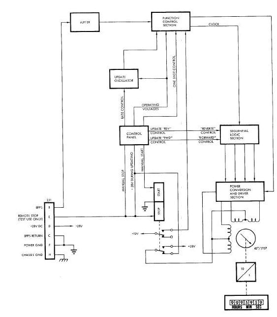
As the counting process begins, three of the flip flops are in the reset condition (reset output positive) and one is in the set condition (set output positive). With receipt of the first timing pulse, the next flip flop switches to the set condition. The first one also remains set, but the other two remain reset. Then, when another timing pulse is received, the first flip flop resets, leaving only the second one set. The sequence continues with alternate timing pulses setting one flip flop, then resetting the preceding one. After the fourth flip flop has been set and the third one subsequently reset, the first one is again switched to the set condition and the sequence is started over again. In order to have the logic section function properly, either a forward or reverse control signal must be received from the start/stop relay. These are used as steering signals for the timing pulses which set and reset the flip flops. For counting up, the control signals cause the flip flop operating sequence to be in one direction. When counting down, they cause the sequence to reverse; flip flop number is set first, then number 3, etc., back through number 1. The output of the sequential logic circuit is applied to the power conversion and driver section.
The power conversion and driver section converts the voltage-pulse outputs of the logic section to current pulses which are used to drive the servomotor. The driver section provides four separate channels, one for each input. Each channel has a logic gate and a power driver. The logic gate permits the logic section output to be sensed at ten selected times each second. The gate senses only the occurrence of a positive signal which will allow the power driver to conduct and send a pulse of current through one of the four servomotor stator windings.
The sequence of pulses from the driver section causes the servomotor to step eight times each second and 45° each step. Figure above illustrates the step positions relative to the sequence of operating pulses from the driver section. If pulses were applied to each of the four servomotor windings, without overlap, the unit would step 90° each repetition. It is this overlapping of signal applications which causes it to step 45° at a time.
The display indicator is a rotating counter with wheels to display seconds, tens of seconds, minutes, and tens of minutes, hours, tens of hours and hundreds of hours' It is coupled to the servomotor through a gear train with a reduction ratio, from the servomotor, of I0:i. Therefore, as the servomotor rotates 360° (in one second), the indicator shaft turns 36° or 1/8 of a rotation. Since the seconds wheel is directly coupled to the shaft and is calibrated from zero to nine, a new decimal is displayed each second. As the seconds wheel moves from nine to zero, the tens-of-seconds wheel moves to the one position. The operations of the other wheels are similar.
The display may be returned to zero or updated to some other readout with the use of the DECR-INCR rotary switch on the face of the timer. The rotary switch must be in the 0 position in order to have the timer operate at a normal rate; with the switch in one of the other position, it counts at a different rate. There are three rate selections, each for the INCR and DECR (count-up and count-down) updating modes. The positions on each side that are farthest from the 0 position are utilized to make the timer count at 25 times its normal rate. The next closer positions are utilized to count at three times the normal rate. The positions nearest the 0 position are used to count at a rate 0.B times the normal one. This position serves to more accurately place the indicator at a desired readout.
Operationally, positioning the rotary switch in some position other than 0 causes the time base frequency from the electronic timer to be replaced in the circuitry by an update oscillator. The frequency of the oscillator is established by the position of the rotary switch. In the 25X positions, the frequency is 400 cycles per second; in the 3Xposition, it is 48 cps; and in the 0.3Xpositions, it is approximately 4.8 cycles per second. The accuracy of the oscillator output is not critical since the oscillator functions only for updating purposes.
Operation of rotary switch supplies a stop command to the electronic circuitry, and start switch must be operated to resume normal count.
The event timer is capable of counting time, either up or down, to a maximum of 59 minutes and 59 seconds. The time is capable of counting time down to zero from any preselected time, up to the maximum listed above.
Note: When the event timer is counting down it will continue through zero if not manually stopped. After counting through zero, the timer will begin counting down from 59 minutes and 59 seconds.
The time is displayed on a decimal display indicator Qn the face of the unit. The seconds tumbler of the display indicator Is further graduated in 0.2 second increments. Counting, In either direction, may be started or stopped either remotely or manually. Prior to starting a counting operation, the indicator must be manually preset to the time from which it is deslred to start counting.
The dimensions of the event time are approximately 2 X 4 x 6 inches and the weight about two pounds. On the face of the timer, there are two toggle switches, one rotary switch, and a decimal display window. (Refer to this Figure) In addition to the panel mounted controls, the unit contains four electronic modules, two relays, a tuning fork resonator, and a step servo motor. A gear train connects the servo motor with the decimal display tumblers. There is one electrical connector on the back of the unit.
The operation of the event timer is independent
of the electronic timer. (Figure Below) It provides its own
time base which is used to control the operation of the decimal display
mechanism. The time base used for normal counting operation is developed
when the output of a tuning for, resonator is connected to a series of
toggle-type flip flops. The resulting signal establishes the repetition
rate of a stop-type servo motor. The servo motor is coupled, through a
gear train, to the display tumblers. Additional counting rates may be
selected in order to rapidly reset the timer to zero or to some other
desired indication.
Event Timer Functional Diagram
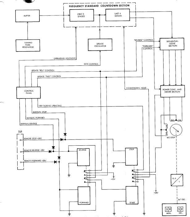
The remote and manual start/stop functions of the timer are accomplished in almost exactly the same manner. The difference is only in the source of the control signals. In order to initiate counting operations by either method, it is necessary to first have the STOP-STBY toggle switch in either the STBY or the center off position. (Refer to this Figure)
Note: When starting is accomplished with the STOP - STBY switch in the center position, a small inaccuracy is incurred. To prevent any starting inaccuracies, the STOP - STBY switch is placed in the STBY position before starting the timer.
Manual starting may then be accomplished by
placing the UP-DN toggle switch in either the UP or the DN position.
This energizes one of the two coils of the forward/reverse relay, also
causing the start coil of the start/stop relay to be forward/reverse
relay, also causing the start coil of the start/stop relay to be
energized. When these events take place, control and operating voltages
are supplied to the counting circuitry, thus allowing the operation to
begin. When starting is to be accomplished remotely, either a remote
forward or a remote reverse signal is transmitted from the ground
station to energize the forward/reverse relay. The counting process may
be stopped upon receipt of a remote stop signal or by placing the
STOP-STBY switch in the STOP position. Either of these functions
energizes the stop side of the start/stop relay, removing critical
operating voltages from the counting circuitry.
Normal counting operations begin with the actuation of the forward/reverse relay in either direction and the start/stop relay in the start direction. When the forward/reverse and the start/stop relays are actuated, an operating voltage of +28 vdc is applied to the servo motor and a ground level inhibit signal is removed from the toggle flip flops. Also, a +12 vdc control signal, denoting either a forward or reverse counting process, is transmitted to the logic circuitry preceding the servo motor. The remainder of the timer circuitry has operating voltages applied when the STOP/STBY switch is placed in STBY.
With the application of operating voltages, the
tuning fork resonator emits and ac signal of 1280 cycles per second. The
signal is passed through a buffer to condition it for use by the series
of seven toggle flip flops in the frequency standard countdown section.
Since the output frequency of each fllp flop is half that of its input,
the final one in the series generates a signal of ten pulses per second.
The outputs of the countdown section are connected to the sequential
logic section and the power conversion and driver section. Sequential
logic section consists of four set-reset flip flops which provide the
necessary sequences of output signals to cause the servo motor to step
in one direction or the other (See Figure).
As the counting process begins, three of the flip flops are in the reset
condition (reset output positive) and one is in the set condition (set
output positive). With receipt of the first timing pulse, the next flip
flop switches to the set condition. The first on also remains set, but
the other two remain reset. Then, when another timing pulse is received,
the first fllp flop resets, leaving only the second one set. The
sequence continues with alternate timing pulses setting one flip flop,
then resetting the preceding one. After the fourth flip flop has been
set and the third one subsequently reset, the
first one Is again switched to the set condition and the sequence is
started over again. In order to have the logic section function
properly, either a forward or reverse control signal must be received
from the forward/reverse relay. These are used as steering signals for
the timing pulses which s_t and reset the flip flops. For counting up,
the control signals cause the flip flop operating sequence to be in one
direction. When counting down, they cause the sequence to reverse: flip
flop number is set first, then number 3, etc., back through number 1.
The power conversion and driver section converts the voltage-pulse outputs of the logic section to current pulses which are used to drive the servo motor. The driver section provides four separate channels, one for each input. Each channel has a logic gate and a power driver. The logic gate permits the logic section output to be sensed at ten selected times each second. The gate senses only the occurrence of a positive signal which will allow the power driver to conduct and send a pulse of current through one of the four servo motor stator windings.
The sequence of pulses from the Driver section
causes the servomotor to step ten times each second and 45° each step.
Figure
above illustrates the step
positions relative to the sequence of operating pulses from the driver
section. If pulses were applied to each of the four servomotor windings,
without overlap, the unit would step 90° each repetition. It is this
overlapping of signal applications
which causes it to step 45° at a time.
The display indicator is a rotating counter with
wheels to display seconds, tens of seconds, minutes, and tens of
minutes. It is coupled to the servomotor through a gear train with a
reduction ratio, from the servomotor, of 12.5:1. Therefore, as the
servomotor rotates 450° (in one seconds), the indicator shaft turns 36°
or 1/10 of a rotation. Since the seconds wheel is directly coupled to
the shaft
and is calibrated from zero to nine, a new decimal is displayed each
second. As the seconds wheel from nine to zero, the tens-of-seconds
wheel moves to the one position. The operations of the other wheels are
similar.
The display may he returned to zero or updated to some other readout with the use of the DECR-INCR rotary switch on the face of the timer. The rotary switch must be in the 0 position in order to have the timer operate at a normal rate; with the switch in one of the other positions, it counts at a different rate. There are three rate selections, each, for the INCR and DECR (count-up and countdown) updating modes. The positions on each side that are farthest from the 0 position are utilized to make the timer count at 25 times its normal rate. The next closer positions are utilized to count at four times the normal rate. The position are used to count at a rate 0.4 times the the normal one. This position serves to more accurately place the indicator the normal one. This position serves to more accurately place the indicator at a desired readout.
Operationally, positioning the rotary switch in
some position other than 0 causes the tuning fork resonator and the
first three toggle flip flops to be replaced in the circuitry by an
update oscillator. The frequency of the oscilator is established by the
position of the rotary switch. In the 25X positions, the frequency is
4,000 cycles per second; in the 4X position, it is 640 cps; and in the
0.4X positions, it is approximately 64 cycles per second. The accuracy
of the oscillator output is not critical since the oscillator functions
only for updating purposes.
The Accutron clock (See Figure), located on the command pilot's control panel. The clock is
approximately 2 3/8 inches square and one inch thick. The clock has a 24
hour dial with major divisions on the half hour. An hour hand, minute
hand and a sweep second hand are provided for a precise indication of
the time of day. The unit is completely self contained and has no
electrical interface
with the spacecraft. The clock is capable of operating continuously for
approximately one year on the internal mercury battery.
The Accutron clock is provided with one control knob. The knob is used to stop, set and start the timer as desired. To stop the timer, the control is depressed. From the depressed position, the clock can be set to the desired time. The clock will start automatically when the control knob is released.
The Accutron clock is a highly accurate device
with an error of less than + 3 seconds per day. This high degree of
accuracy is made possible by using a tuning fork as the time standard,
instead of the conventional balance wheel and hair spring. The tuning
fork is magnetically driven at a natural frequency of 360 cps. The
tuning fork frequency is adjustable, making precise calibration of the
clock
possible. The vibrational motion of the tuning fork is converted to
rotational motion to provide outputs of: one revolution per day, one
revolution per hour and one revolution per minute, for the clock hands.
The mechanical clock is shown in this Figure. The unlt is approximately 2 1/4 x 2 /4 x 3/4 inches and weighs about one pound. The dial face is calibrated in increments of 0-24 and 0-60. The clock has two hands for the time of day portion and two for the stopwatch portion. The controls for operating both portions of the clock are located on the face of the unit.
The clock is a mechanical device which is
self-powered and required no outside inputs. The hand and dial-face
clock displays Greenwich Mean Time in hours and minutes. A control on
the face provides for winding and setting the unit. With the passing of
each 24-hour period, the calendar date indicator advances to the next
consecutive number. The stopwatch portion of the clock can be started,
stopped, and returned to zero at any time. Two settable markers are
provided on the minute dial to provide a time memory, permitting the
clock to serve as a short-term back-up timer.
at a desired readout.
DOD - Department of Defense (DOD)
ET - Elapsed Time (ET)
GMT - Greenwich Mean Time (GMT)
LSB - Least Significant Bit (LSB)
MDIU - Manual Data Insertion Unit (MDIU)
TCB - Time Correlation Buffer (TCB)
TTG to TR - Time-To-Go to retrofire (TTG to TR)
TRS - Time Reference System (TRS)
TTG to TX - Time-To-Go to equipment reset (TTG to TX)