Propulsion
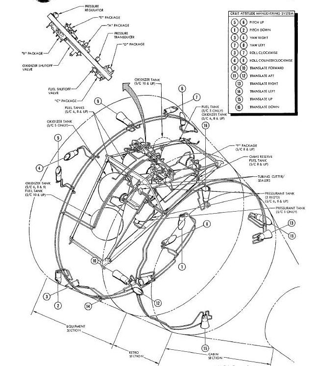
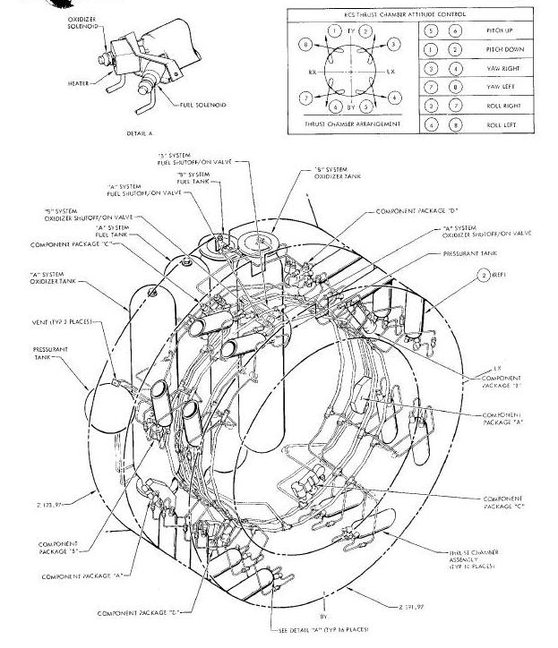
Orbit Attitude Maneuvering System and TCA Location Diagram
ORBIT ATTITUDE AND MANUVERING SYSTEM
OAMS Control and Indicator Schematic
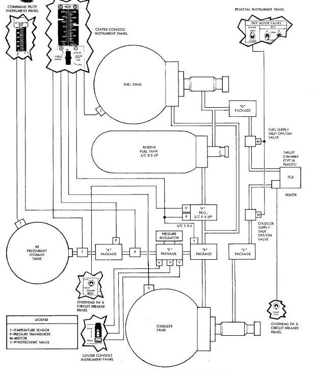
Orbit Attitude Maneuvering System Schematic
Thrust Chamber Assembly (TCA) Group
Thrust Chamber Assembly (TCA) Group
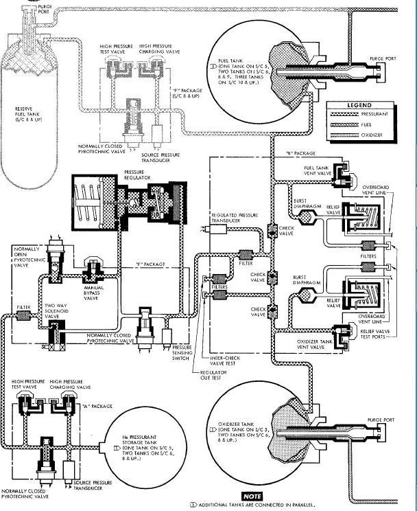
OAMS and RCS "A" Package and OAMS "F" Package Diagram
"F" Package (Spacecraft 8 thru 12 Only)
OAMS and RCS Pressure Regulator Diagram
OAMS and RCS "B" Package Diagram
Reserve Fuel Tank (Spacecraft 8 thru 12 only)
OAMS and RCS "C" and "D" Package Diagram
Propellant Supply Shutoff Valves
OAMS and RCS Propellant Shutoff Valve Diagram
Thrust Chamber Assembly (TCA) Group
Re-Entry Control "A" and "B" Systems Diagram
Thrust Chamber Assembly (TCA) Group
Thrust Chamber Assembly (TCA) Group
Propellant Supply Shutoff Valves
The Gemini Spacecraft is provided with an attitude and maneuvering
control capability. (Figure Below). This control capability is used
during the entire spacecraft mission, from the time of launch vehicle
separation until the reentry phase is completed. Spacecraft control is
accomplished by two rocket engine systems, the Orbit Attitude and
Maneuvering System (OAMS) and the Re-entry
Control System (RCS).
Orbit Attitude Maneuvering System and TCA Location Diagram
The OAMS controls the spacecraft attitude and provides maneuver
capability from the time of launch vehicle separation until the
initiation of the retrograde phase of the mission. The RCS provides
attitude control for the re-entry module during the re-entry phase of
the mission. The 0AMS and RCS respond to electrical commands from the
Attitude Control Maneuvering Electronics (ACME) in the
automatic mode or from the crew in the manual mode.
ORBIT ATTITUDE AND MANUVERING SYSTEM
The Orbit Attitude Maneuvering System (OAMS) (Figure Above) is a fixed thrust, cold gas pressurized, storable liquid, hypergolic bi-propellant, self contained propulsion system which is capable of operating in the environment outside the earth's atmosphere. Maneuvering capability is obtained by firing thrust chamber assemblies (TCA) singly or in groups. The thrust chamber assemblies are mounted at various points about the adapter in locations consistent with the modes of rotational or translation acceleration required.
OAMS Control and Indicator Schematic
The OAMS provides a means of rotating the spacecraft about its three attitude control axes (roll, pitch, and yaw) and translation control in six directions (right, left, up, down, forward and aft). The combination of attitude and translational maneuvering creates the capability of rendezvous and docking with another space vehicle in orbit.
The primary purpose of OAMS is spacecraft control in orbit. The OAMS
is also used, after firing of shaped charges, to separate the Spacecraft
from the launch vehicle during a normal launch or in case of an abort
which may occur late in the launch phase. During initiation of
retrograde sequence, tubing cutter/sealer devices sever and seal the
propellant feed lines from the equipment adapter. All
of the OAMS (except six TCA's located in retro section) are separated
from the spacecraft with the equipment section of the adapter.
Spacecraft control functions are then assumed by the Re-entry Control
System (RCS). OAMS control units and tanks are mounted on a structural
frame (module concept) in the equipment section. The control units
consist of forged and welded "packages" Each package consists of several
functioning components and filters. The OAMS Control and Indicator
Schematic (Figure Below) is a simplified schematic of the indicators and
manual controls which are directly related to the Propulsion System.
Additional controls
are provided by the Attitude Control and Maneuvering Electronics (ACME)
System The delivery of pressurant, fuel and oxidizer is accomplished by
a uniquely brazed tubing manifold system. The OAMS system is divided
into three groups; pressurant group, fuel/oxidizer group and Thrust
Chamber Assembly (TCA) group.
The pressurant group (Figure below) consists of a pressurant tank,
"A" package, "E" package, "F" package on Spacecraft 8 thru 12, pressure
regulator, and "B" package. Inlet valves, ports and test ports are
provided at accessible points to permit servicing, venting, purging and
testing. Filters are provided throughout the system to prevent
contamination of the system. The pressurant is isolated
in the storage tank during pro-launch periods by a normally closed
pyrotechnic actuated valve, located in the "A" package. On Spacecraft 8
thru 12, the pressurant is isolated from the reserve fuel tank by the
"F" package.
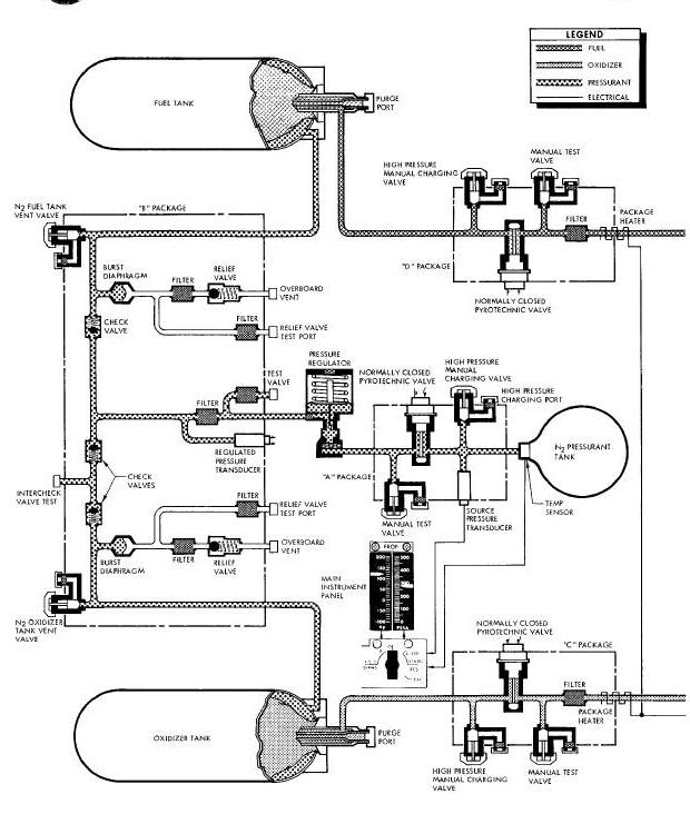
Orbit Attitude Maneuvering System Schematic
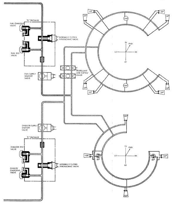
The fuel/oxidizer (propellant) group (Figure
Above) consists of expulsion bladder storage tanks, "C" and "D"
packages and two propellant shut off valves. Charging valves and ports
and test valves and ports are provided at accessible points to permit
servicing, venting, purging and testing. The propellants are isolated in
the storage tanks by normally closed, pyrotechnic actuated valves ("C"
and "D" packages). Filters are provided in the "C" and "D" packages,
down stream of the isolation valves, to guard against contamination of
the thrust chamber assemblies.
The propellants used are:
- OXIDIZER - nitrogen tetroxide (N2O4) conforming to specification MIL - P - 26539 A
- FUEL - monomethyl hydrazine (N2H3CH3) conforming to specification MIL - P - 27404
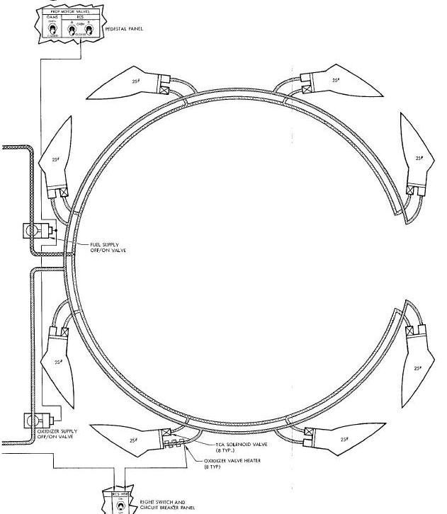
Thrust Chamber Assembly (TCA) Group
The TCA group consists of thrust chambers and electrical solenoid valves. Sixteen TCA's are used per spacecraft (Figure 8-94 Above). Eight twenty-five pound thrust capacity TCA's are used for attitude control, (roll, pitch and yaw). Six one-hundred pound and two eight-five pound thrust capacity TCA's are used for translational maneuvering.
The pressurant tank contains high pressure helium (He) stored at 3000 PSI. (Figure Above). The tank is serviced through the "A" package high pressure gas charging port. Pressure from the pressurant tank is isolated from the remainder of the system by a normally closed pyrotechnic actuated isolation valve located in the "A" package. Upon command, the system isolation valve is opened and pressurized helium flows through the "E" package, to the pressure regulator, "B" package and propellant tanks. Normally, pressurant is controlled through system pressure regulator, and regulated pressure flows to the "B" package. The "B" package serves to deliver pressurant at regulated pressure to the fuel and oxidizer tanks, imposing pressure on the propellant tank bladder exteriors. Relief valves in the "B" package prevent over pressurization of the System downstream of the regulator. Burst diaphragms are provided in series with the relief valves, in the "B" package, to provide a positive leak tight seal between system pressure and the relief valve.
The "E" package provides a secondary mode of pressure regulation in
the event of regulator failure. In the event of regulator over-pressure
failure, resulting in excess pressure passage through the regulator, a
pressure switch ("E" package) intervenes and automatically closes the
normally open cartridge valve. Regulated pressure is then controlled
manually by the crew by momentary placing the OAMS REG switch in the
PULSE position. (Figure Above).
Control pressure information is obtained from the "B" package regulated
pressure transducer on spacecraft 5 and 6, the "F" package pressure
transducer on spacecraft 8 thru 12. Should
regulator under-pressure failure occur, the crew can manually select the
OAMS-REG switch to SQUIB. This selection opens the normally closed valve
and closes the normally open valve, thus pressurant by-passes the
regulator completely. Pressure is then regulated manually (OAMS-PULSE)
by the crew with control pressure information obtained from the "B"
package regulated pressure transducer on spacecraft 5 and 6, the "F"
package pressure transducer on spacecraft 8 thru 12. The "B" package
provides a division of pressurant flow to the propellant tanks. The
regulated pressure is sensed by the pressure transducer and provides a
signal to the
cabin instrument, (Figure Above)
indicating pressure downstream of the regulator. In the event of
regulator failure, the crew utilizes the reading to manually maintain
the required pressure in the system. Three check valves prevent back
flow of propellant vapors into the pressurant system. The "B" package
also affords a safety feature for prevention of over pressure on the
fuel and oxidizer tank bladders. Should the system be over pressurized
downstream of the regulator the over pressure would first rupture the
burst diaphragms, then he vented overboard through the relief valves.
The relief valves will reset when system pressure returns to normal.
On spacecraft 8 thru 12, the pressurant flows from the "B" package to the "F" package. The normally closed pyrotechnic valve in the "F" package is opened by placing the 0AMS RESV switch (Figure Above) in the SQUIB position, allowing pressurant to flow to the reserve fuel tank.
Fuel and oxidizer are stored in their respective tank: and are
isolated from the remainder of the system by normally closed pyrotechnic
valves in the "C" (oxidizer) and "D" (fuel) packages. Upon command, the
"A" (pressurant), "C" and "D" package isolation valves are opened. The
pressurant imposes )ressure on the propellant tank bladders and fuel and
oxidizer are distributed through their separate tubing manifold systems
to the inlet of the thrust chamber solenoid valves. Upon command on
spacecraft 8 thru 12, the normally closed pyrotechnic valve in the "F"
package is opened to allow pressurant to impose pressure on the reserve
fuel tank bladder
to distribute reserve fuel to the thrust chamber solenoid valve. Two
electrically operated motor control valves (Figure
Above) are located in the propellant feed lines, upstream of
the TCS's. In the event of fuel or oxidizer leakage through the TCA
solenoid valves, the motor operated valves can be closed by the crew to
prevent loss of propellants. The valves can again be actuated open by
the crew, when required, to deliver propellants to TCA solenoids.
Thrust Chamber Assembly (TCA) Group
Upon command from the automatic or manual controls, signals are
transmitted through the Attitude Control Maneuvering Electronics (ACME)
to selected TCA's to open simultaneously the normally closed,
quick-acting fuel and oxidizer solenoid valves mounted on each TCA. In
response to these commands, propellants are directed through all
injector Jets into the combustion chamber. The controlled l
fuel and oxidizer impinge on one another, where they ignite
hypergollcally to burn and create thrust. Heaters are connected to each
TCA oxidizer solenoid valve to prevent freeze-up and are activated by an
OAMS RTRS switch (Figure Above).
The helium pressurant is stored in welded, titanium spherical tank. Tank dimension is 16.20 inches outside diameter and has an internal volume of 1696.0 cubic inches. The helium gas is stored at 3000 psi rand held therein by the "A" package normally closed pyrotechnic actuated valve. The pressurized helium is used to expel the fuel and oxidizer from their respective tanks. Temperature sensors are affixed to the pressurant tank and outlet line to provide readings for the cabin instrument and telemetry.
The "a" package (Figure below)
consists of a source pressure transducer, isolation valve, two high
pressure gas charging _nd test valves and filters. The source pressure
transducer monitors tank pressure and transmits an electric signal to
the propellant indicator in the cabin and to the Instrumentation System.
The normally closed pyrotechnic isolation valve is used to isolate
pressure from the remainder of the system. The valve is actuated to the
open position to activate the system for operation. Two dual seal, high
pressure gas charging valves and ports are provided, one on each side of
the isolation valve. The upstream valve is used for servicing, purging
and venting the pressurant tank, while the downstream valve is used to
test downstream components. The valve
filters prevent system contamination during testing and servicing.
OAMS and RCS "A" Package and OAMS "F" Package Diagram
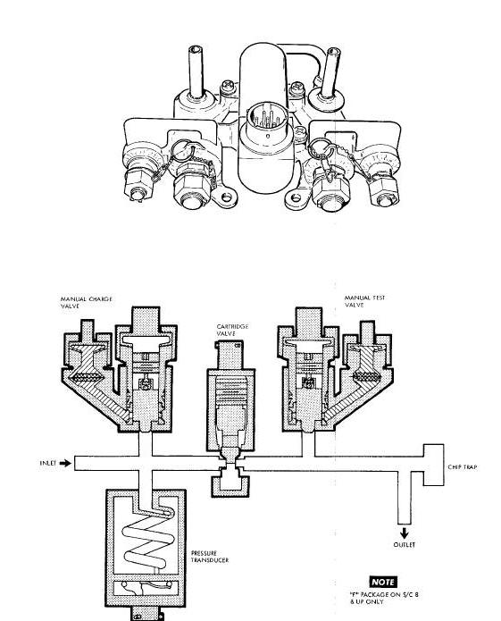
"F" Package (Spacecraft 8 thru 12 Only)
The "F" package (Figure Above) consists of a source pressure transducer, isolation valve, two high pressure gas charging and test valves and filters. The source pressure transducer monitors the regulated pressure and transmits an electrical signal to the cabin indicator and Instrumentation System, indicating the amount of regulated pressure for the OAMS system. The normally closed pyrotechnic valve is used to isolate the pressurant from the reserve fuel tank. The valve is actuated to the open position to activate the reserve fuel system for operation. Two dual seal, high pressure gas charging valves and ports are provided, one on each side of the isolation valve. The valve filters prevent system contamination during testing and servicing.
The "E" package (Figure Below)
consists of a filter, one normally open pyrotechnic actuated valve, one
normally closed pyrotechnic actuated valve, a normally closed two way
solenoid valve, a pressure sensing switch, and a manual by-pass valve.
The input filter prevents any contaminants from the "A" package from
entering the "E" package. The two pyrotechnic actuated valves are
activated (open to closed and closed to open) as required to maintain
regulated system pressure, in the event of system regulator malfunction.
The two way (open-close) solenoid valve is normally closed and functions
upon crew command to maintain regulated system pressure in the event of
a system regulator malfunction. The pressure switch senses regulated
pressure from the system regulator. Upon sensing over pressure, the
pressure switch intervenes and causes the normally open valve to actuate
to the closed position, closing the inlet to the pressure regulator. The
solenoid valve, when opened, allows pressurant flow through the package
after the normally opened valve is actuated to the closed position. The
manual by-pass (normal open) test valve is used to divert pressure to
the solenoid valve, during system test.
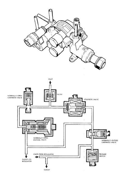
In the normal mode of operation, gas flows through the normally open pyrotechnic valve to the system regulator. In the event system regulator over pressure malfunction the pressure switch intervenes and causes the normally opened pyrotechnic valve to actuate to the closed position, diverting pressure to the normally closed solenoid valve. The solenoid valve is manually controlled (pulsed) by the crew to maintain regulated system pressure. In the event of system regulator (under pressure) malfunction 3 the normally closed pyrotechnic valve can be actuated to the open position. Simultaneously insured by the circuitry, the normally open valve is activated to the closed position. This prevents by-pass of the solenoid valve. In this mode, a regulator by-pass circuit is provided and pressure is regulated by the crew.
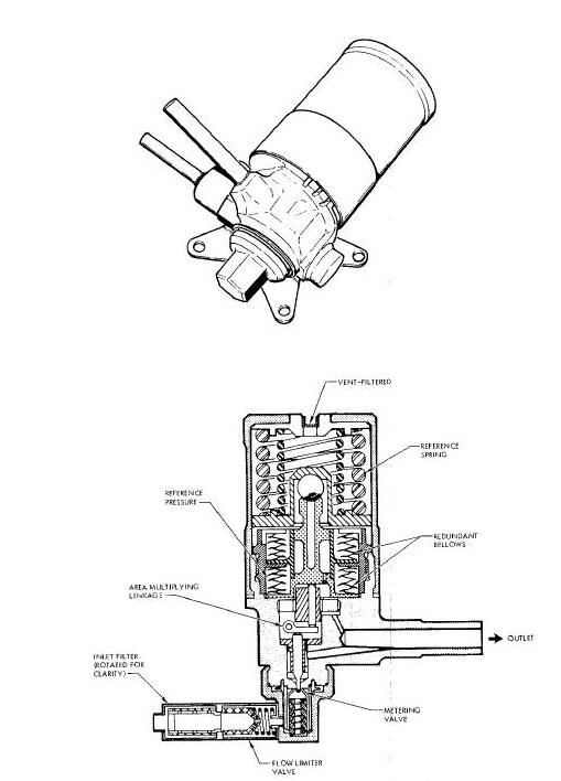
The pressure regulator (Figure below)
is a conventional, mechanical-pneumatic type. The regulator functions to
reduce the source pressure to regulated system pressure. An inlet filter
is provided to reduce any contaminants in the gas to an acceptable
level. An outlet llne is provided from the regulated pressure chamber to
the pressure switch ("E" package) and activates the switch in the
event of an over pressure malfunction.
OAMS and RCS Pressure Regulator Diagram
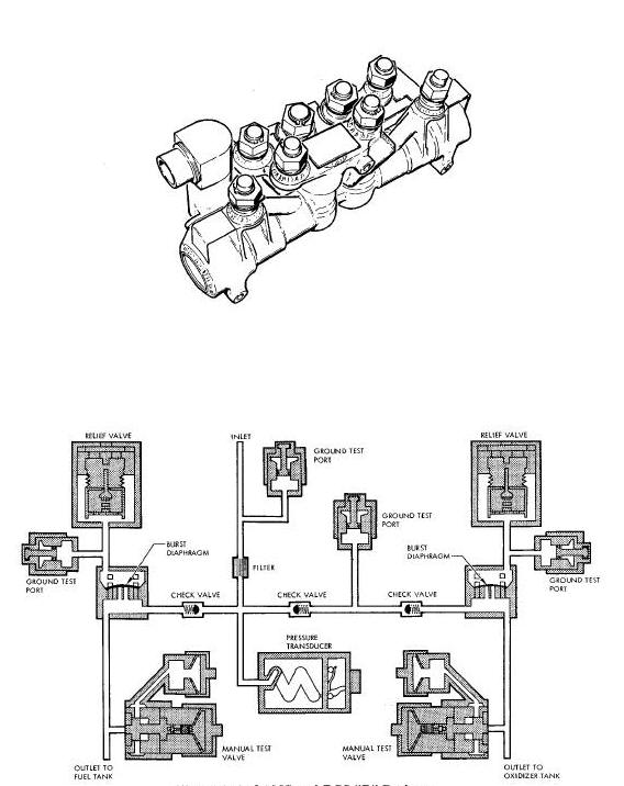
The "B" package (Figure Below) consists of filters, regulated pressure transducer, three check valves, two burst diaphragm, two relief valves, regulator out test port, fuel tank vent valve, Inter-check valve test port, oxidizer tank vent valve, and two relief valve test ports. The inlet filter reduces any contaminants in the gas to an acceptable level. Test valve inlet filters prevent any contaminants from entering the system. The regulated pressure transducer monitors the regulated pressure and transmits an electric signal to the cabin indicator and Instrumentation System, indicating the amount of regulated pressure on spacecraft 5 and 6. A single check valve prevents backflow of fuel vapors into the gas system. Two check valves are provided on the oxidizer side to prevent backflow of oxidizer into the system. The burst diaphragms are safety (over pressure) devices that rupture when regulated pressure reaches the design failure pressure, preventing excessive pressure from being imposed on the propellant bladders. The two relief valves are conventional, mechanical-pneumatic type with preset opening pressure. In the event of burst diaphragm rupture, the relief valve opens venting excess pressure overboard. The valve reseats to the closed position when a safe pressure level is reached, thereby, prevents venting the entire gas source. Manual valves and ports are provided to vent, purge and test the regulated system.
OAMS and RCS "B" Package Diagram
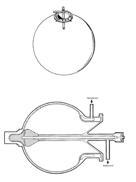
The fuel storage tank (Figure Below) is welded, titanium
spherical tank which contain an internal bladder and purge port. The
tank dimension is 21.13 inches in diameter, and has a fluid volume
capacity of 5355.0! cubic inches. The tank bladder is a triple layered
Teflon, positive expulsion type. The helium pressurant is imposed on the
exterior of the bladder to expel the fuel through the
"D" package to the thrust chamber solenoid valves. Purge ports are
provided to purge and vent the fuel tank. Temperature sensors are
affixed to the input pressurant line, fuel tank exterior and output line
to provide readings for the cabin indicator and Instrumentation System.
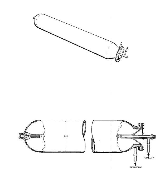
Reserve Fuel Tank (Spacecraft 8 thru 12 only)
The reserve fuel tank (Figure 8-102 Below) is a welded titanium cylindrical tank which contains an internal bladder and purge port. The tank is 5.10 inches outside diameter, 30.7 inches in length end has a liquid volume capacity of 546.0 cubic inches. The helium pressurant is imposed on the exterior of the bladder to expel fuel through the "D" package to the thrust chamber solenoid valves.
The oxidizer tank (Figure Above) is a welded titanium spherical tank which contain a bladder and purge port. The tank is 21.12 inches in diameter, and has a fluid volume capacity of 5355.0 cubic inches. The tank bladder is double layered Teflon, positive expulsion type. The helium pressurant is imposed on the exterior of the bladder to expel the oxidizer through the "C" package to the thrust chamber solenoid valves. Purge ports are provided to purge and vent the oxidizer tanks. Temperature sensors are affixed to the input pressurant line, oxidizer tank exterior and output line to provide readings for the cabin indicator and Instrumentation System.
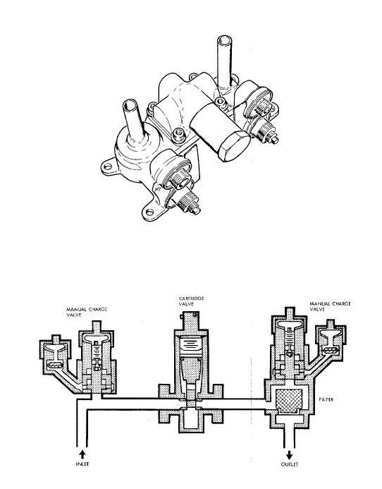
The "C" (oxidizer) and "D" (fuel) packages (Figure
Below) are identical in function and are located downstream
of the tanks of their respective system. Each package consists of a
filter, isolation valve, propellant charging valve and test valve. The
filter is located at the outlet port to prevent contaminants from
entering the downstream system. The normally closed isolation valve is
used
to isolate propellants from the remainder of the system during the
pre-launch waiting period. The pyrotechnic isolation valve is actuated
to the open position for system operation. The propellant charging valve
is located upstream of the isolation valve and is used for servicing and
venting the system. The test valve is located downstream of the
isolation valve and is used to test the
downstream system.
OAMS and RCS "C" and "D" Package Diagram
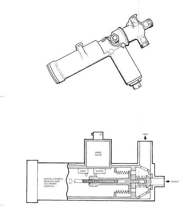
Propellant Supply Shutoff Valves
Propellant supply shutoff valves (Figure
Below) are provided for both the oxidizer and fuel system
and are located downstream of the "C" and "D" packages. The motor driven
shutoff valves are electrically operated and manually controlled. The
propellant valves serve as safeguards in the event of TCA leakage. The
valves are normally in the open position, and are closed at the option
of the
crew to prevent loss of propellants. The valve is thereafter reopened
only when it is necessary to actuate the TCA's for the purpose of the
spacecraft control.
OAMS and RCS Propellant Shutoff Valve Diagram
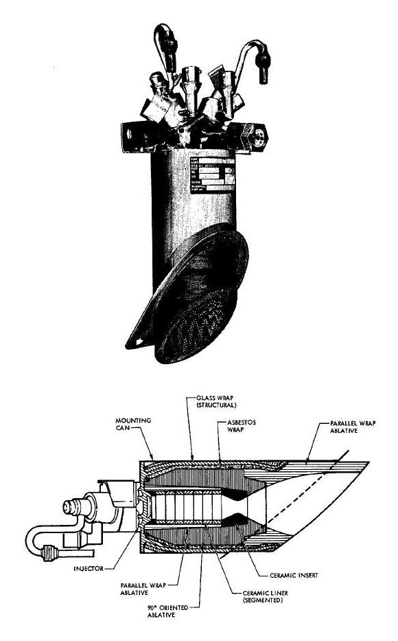
Thrust Chamber Assembly (TCA) Group
Each TCA (Figures for 25lbs. 85lbs. and 100lbs. Below) consists of two propellant solenoid valves, an electric heater, injection system, calibrated orifices, combustion chamber and an expansion nozzle. The propellant solenoid valves are quick acting, normally closed valves, which open simultaneously upon application of an electric signal. This action permits fuel and oxidizer flow to the injector system. The injectors utilize precise Jets to impinge fuel and oxidizer streams on one another for controlled mixing and combustion. The calibrated orifices are fixed devices used to control propellant flow. Hypergolic ignition occurs in the combustion chamber. The combustion chamber and expansion nozzle are lined with ablative materials and insulation to absorb and dissipate heat, and control wall temperature.
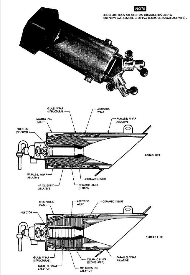
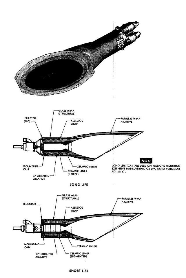
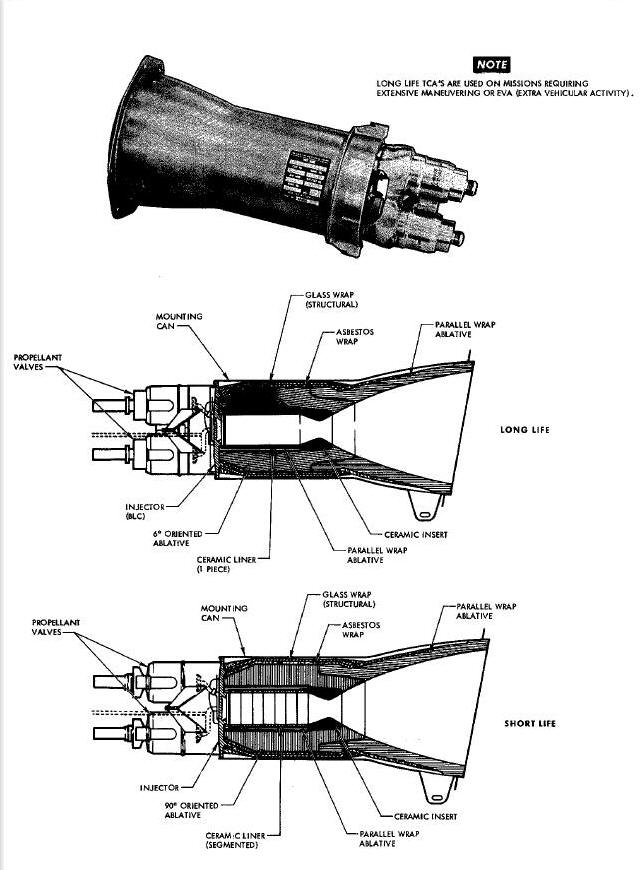
TCA's are installed within the adapter with the nozzle exits terminating flush with the outer moldline and located at various points about the adapter section suitable for the attitude and maneuvering control required. Electric heaters are installed on the TCA oxidizer lines to prevent the oxidizer from freezing.
The tubing cutter/sealer is a pyrotechnic actuated device and serves to positively seal and cut the propellant feed lines. Two such devices are provided for each feed line and are located downstream of the propellant supply on/off valve, one each in the retrograde and equipment section of the adapter. Prior to retrofire, the equipment section is Jettisoned. The devices are actuated to permit separation of the feed lines crossing the parting line, and to contain the propellants upon separation.
The Re-entry Control System (RCS) (Figure Below) is a fixed thrust, cold gas pressurized, storable liquid, hypergolic hi-propellant, self contained propulsion system used to provide attitude control of the spacecraft during re-entry.
NOTE: The RCS consists of two identical but entirely
separate and independent systems. The systems may be operated
individually or simultaneously. One system will be described, all data is
applicable to either system.
The RCS is capable of operating outside of the earth's atmosphere.
Re-Entry Control "A" and "B" Systems Diagram
Attitude control (roll, pitch and yaw) is obtained by firing the TCA's in groups. The TCA's are mounted at various points about the RCS section of the spacecraft consistent with the modes of rotational control required. The entire RCS, (tanks and control packages), with the exception of instrumentation, is located in the RCS section of the spacecraft. Each package consists of several functioning components and filters. The delivery of pressurants and propellants is accomplished by a uniquely brazed tubing manifold system. The HCS is divided into three groups; pressurant group, the oxidizer/fuel (propellant) group and the Thrust Chamber Assembly (TCA) group.
The pressurant group (Figure Below) consists of a pressurant tank, "A" package, pressure regulator and "B" package. Valves and test ports are provided at accessible points to permit servicing, venting, purging and testing. Filters are provided throughout the system to prevent system contamination. The pressurant is stored and isolated from the remainder of the system during pre-launch periods by a normally closed pyrotechnic actuated valve, located in the "A" package.
The fuel/oxidizer (propellant) group (Figure Above) consists of expulsion bladder storage tanks, "C" (oxidizer) and "D" (fuel) packages Valves, ports and test ports are provided at accessible areas to permit servicing, venting, purging and testing. Filters are provided throughout the system to prevent contamination. The propellants are isolated in the storage tanks from the reminder of the system by normally closed pyrotechnic actuated valves in the "C" and "D" packages. Heaters are provided on the "C" package to maintain the oxidizer at an operating temperature.
The propellants used are:
- Oxidizer - Nitrogen Tetroxide (N2O4) conforming to Specification MIL - P - 26539A
- Fuel - Monomethyl Hydrazine (_H3CH3) conforming to specification MIL - P - 27404
Thrust Chamber Assembly (TCA) Group
The TCA group (Figure Above) consists of eight twenty-five pound TCA's used for attitude (roll, pitch and yaw) control of the re-entry module. Each TCA is equipped with thrust chamber and electric controlled solenoid valves. Heaters are provided on the oxidizer solenoid valves to maintain the oxidizer at an operating temperature.
(Figure Above) High pressure
nitrogen (N2) (pressurant), is stored at 3000 psi in the pressurant
tank. The tank is serviced through the "A" package high pressure gas
charging port. Pressure from the pressurant tank is isolated from the
re-mainder of the system, until ready for operation, by a normally closed
pyrotechnic actuated valve located in the "A" package. Stored nitrogen
pressure is monitored and transmitted to the cabin indicator and
Instrumentation System by the source pressure transducer located in the
"A" package. Upon command, the "A" package pyrotechnic actuated valve is
opened (simultaneously with propellant "C" and
"D" package pyrotechnic actuated valves) and nitrogen flows to the
pressure regulator and "B" package. The "B" package provides a division
of flow to the propellant tanks. The regulated pressure is sensed by the
regulated pressure transducer ("B package) and provides a signal to the
Instrumentation System, indicating pressure downstream of the regulator.
The check valves prevent backflow
of propellant vapors into the pressurant system. The "B" package also
provides a safety feature to prevent over pressure of the fuel and
oxidizer tank bladders. Should the system be over pressurized downstream
of the regulator the over pressure would first rupture the burst
diaphragms then be vented overboard through the relief valves.
Fuel and oxidizer (propellants) are stored in their respective tanks,
and are serviced through the high pressure charging ports in the "c" and
"D" packages. The propellants are isolated from the remainder of the
system, until ready for operation, by the normally closed pyrotechnic
valves in the "C" and "D" packages. Upon command the "A" (pressurant),
"C" (oxidizer) and "D" (fuel) package pyrotechnic
actuated valves are opened and propellants are distributed through their
separate tubing manifold system to the thrust chamber inlet solenoid
valves.
Two motor driven shutoff valves are located in the propellant feed
lines, upstream of the TCA's. In the event of fuel or oxidizer leakage
through the TCA solenoid valves, the motor operated valves can be closed
by the crew to prevent loss of propellants. The valves can again be
actuated open by the crew, when required, to deliver propellants to the
TCA solenoids. Heaters are connected to
the output lines of the "C" and "D" packages and are activated by the
RCS HTR switch (Figure Above).
Thrust Chamber Assembly (TCA) Group
Upon command from the automatic or manual controls, signals are transmitted through the Attitude Control Maneuvers Electronics (ACME) to selected TCA's to open simultaneously, the normally closed, quick acting fuel and oxidizer solenoid valves mounted on each TCA. In response to the signals, propellants are directed through small injector Jets into the combustion chamber. The controlled fuel and oxidizer impinge on one another where they ignite hypergolically to burn and create thrust. Heaters are connected to each TCA oxidizer solenoid valve to prevent freeze-up and are activated by the RCS H_ switch (Figure Above).
The nitrogen (N2) pressurant is stored in a welded, titanium spherical tank. The tank is 7.25 inches outside diameter and has an internal volume of 185.0 cubic inches. Nitrogen gas is stored at SO00 _si and held therein by the "A" package pyrotechic valve. This nitrogen, under pressure, is used to expel the fuel and oxidizer from their respective tanks. Temperature sensors are affixed to the pressurant outlet line to provide readings for the cabin instrument and telemetry.
The "A" package (Figure Above)
consists of a source pressure transducer, isolation valve, filters and
two high pressure gas charging valves. The source pressure transducer
monitors the stored pressure and transmits an electric signal to the
cabin indicator indicating the pressure of the stored gas. The normally
closed isolation valve is used to isolate the pressure from the
remainder of the
system.
The valve is pyrotechnically actuated to the open position to activate the system for operation. Two dual seal, high pressure gas charging valves and ports are provided, one on each side of the isolation valve. The upstream valve is used for servicing, venting and purging the pressuraut tank, while the downstream valve is used to test downstream components. Filters are provided to prevent contaminants from entering the system.
The pressure regulator (Figure Above) is a conventional , mechanical-pneumatic type. The regulator functions to reduce the source pressure to related system pressure. An inlet filter is provided to reduce any contaminants in the gas to an acceptable level.
The "B" package (Figure Above) consists of filters, regulated pressure transducer, three check valves, two burst diaphragms, two relief valves, regulator output test port, fuel tank vent valve, oxidizer tank vent valve, inter-check valve test port and two relief valve test ports. The inlet filter reduces any contaminants in the gas to an acceptable level. Valve inlet filter prevent contaminants from entering the system. The pressure transducer monitors the regulated pressure and transmits an electrical signal to the spacecraft Instrumentation System. A single check valve prevents backflow of fuel vapors into the gas system. Two check valves are provided on the oxidizer side to prevent backflow of oxidizer vapor into the gas system. The Burst diaphragms are safety devices that rupture when the regulated pressure reaches the design failure pressure, preventing excessive pressure from being imposed on the propellant bladders.
The two relief valves are conventional mechanical-pneumatic type with
preset opening pressure. In the event of burst diaphragm rupture, the
relief valve opens, venting excess pressure overboard. The valve reseats
to the closed position when a safe level is reached, preventing the
entire gas source from being vented overboard. Manual valves and ports
are provided to vent, purge and test
the regulated system.
The fuel tank (Figure Above)
is a welded, titanium cylindrical tank which contains an internal
bladder and purge port. The tank is 5.10 inches outside diameter, 30.7
inches in length and has a fluid volume capacity of 546.0 cubic inches.
The nitrogen pressurant is imposed on the exterior of the bladder to
expel fuel through the "D" package to the TCA solenoid valves. The purge
port is provided
to purge and vent the fuel tank bladder. Temperature sensors are affixed
to the nitrogen input line and fUel output line to transmit signals to
Instrumentation System.
The oxidizer tank (Figure Above) is a welded, titanium cylindrical tank which contains a bladder and purge port. The tank is 5.10 inches outside diameter, 25.2 inches in length and has a fluid volume capacity of 439.0 cubic inches. The bladder is a double layered Teflon, positive expulsion type. The nitrogen pressurant is imposed on the exterior of the bladder to expel the oxidizer through the "C" package to the TCA solenoid valve. The purge port is provided for purging and venting the oxidizer tank bladder. Temperature sensors are affixed to the nitrogen input line and oxidizer output line to transmit signals to Instrumentation System.
The "C" and "D" packages (Figure
Above) are identical in function and are located downstream of
the tanks of their respective system. Each package consists of filters,
an isolation valve propellant charging valve and test valve. The filter,
located at outlet ports reduces contaminants tO an acceptable level. The
valve and port filters prevent contaminants from entering the system.
The normally
closed isolation valve is used to isolate propellants from the remainder
of the system during the pro-launch period. The isolation valve is
pyrotechnic actuated to the open position for system operation. The
propellant charging valve is located upstream of the isolation valve and
is used for servicing and venting the system. The test valve is located
downstream of the isolation valve and is used to test the downstream
system.
Propellant Supply Shutoff Valves
Propellant supply shutoff valves (Figure Above) are provided for both the oxidizer and fuel system, and are located downstream of the "C" and "D" packages in the system. The motor driven shutoff valves are electrically operated, and manually controlled. The valves are normally in the open position, and are closed at the option of the crew to prevent loss of propellants. The valves are reopened only when the TCA's are needed for spacecraft control.
Each TCA (Figure 8-110 Below) consists of two propellant valves, injection system, calibrated orifices, combustion chamber and expansion nozzle. The fuel and oxidizer solenoid valves are quick acting, normally closed valves, which open simultaneously upon application of an electric signal. The action permits fuel and oxidizer flow into the injector system. The injectors use precise Jets to impinge fuel and oxidizer streams on one another for controlled mixing and combustion. The calibrated orifices are fixed devices used to control propellant flow. Hypergolic ignition occurs in the combustion chamber. The combustion chamber and expansion nozzle is lined with ablative materials and insulation to absorb and dissipate heat and control external wall temperature. TCA's are installed within the RCS section mold line, with the nozzles terminating flush with the outer mold line. TCA's are located at fixed points in the RCS section in a location suitable for attitude control. Electric heaters , located on the oxidizer valve, are used to prevent the oxidizer from freezing.
RCS 25 Lbs.TCA Diagram
A
ACME - Attitude Control Maneuvering Electronics (ACME)
O
OAMS - Orbit Attitude and Maneuvering System (OAMS)
R
RCS - Re-entry Control System (RCS)
T
Thrust Chamber Assemblies (TCA)