 |
Instrumentation
Instrumentation System Components
Instrumentation System Signal Flow Block Diagram
Instrumentation System Power Control Circuitry Functional Diagram
Sequential System Parameters Functional Diagram
ELECTRICAL POWER SYSTEM PARAMETERS
Electrical Power System Parameters Functional Diagram
ENVIRONMENTAL CONTROL SYSTEM PARAMETER
Environmental Control System Parameter Functional Diagram
Inertial Guidance System Parameters Block Diagram
ATTITUDE CONTROL AND MANEUVERING ELECTRONICS PROGRAMMERS
Attitude Control & Maneuvering Electronics Parameters Block Diagram
Orbit, Attitude & Maneuvering System Parameters Block Diagram
RE-ENTRY CONTROL SYSTEM PARAMETERS
Re-Entry Control System Parameters Block Diagram
AERODYNAMIC AND CREW CONTROL PARAMETERS
Aerodynamic and Crew Control Parameters Block Diagram
COMMUNICATION SYSTEM PARAMETERS
Communication System Parameters Block Diagram
INSTRUMENTATION SYSTEM PARAMETERS
Instrumentation System Parameters Block Diagram
Physiological Parameters Block Diagram
Rendezvous Radar Parameters Block Diagram
Synchro Repeaters and Schematic Diagram
C02 Partial Pressure Detector and Schematic Diagram
Servo Accelerometer and Schematic Diagram
Instrumentation Package Assemblies
Instrumentation System Multiplexers Diagram
Instrumentation System Programmer Diagram
Multiplexer/Encoder System Block Diagram
BIO-MED TAPE RECORDERS AND POWER SUPPLY
The Instrumentation System provides a means of data acquisition with respect to the performance and operation of the spacecraft throughout its mission. Data acquisition is defined as the sensing of specific conditions or events on board the spacecraft, displaying the derived data from these inputs to the crew and ground operation personnel, and recording and later processing this data for use in post flight reports and analysis. In this respect the data acquisition function is shared by all spacecraft systems, the ground operational support system, and the data processing facility.
Basically, the instrumentation Parameters are divided into two categories : operational and nonoperational. Operational parameters are those which are necessary for determining the progress of the mission, assessing spacecraft status, and making decisions concerning flight safety. Nonoperational parameters are those which are required for post mission analysis and evaluation.
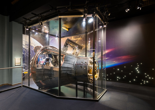
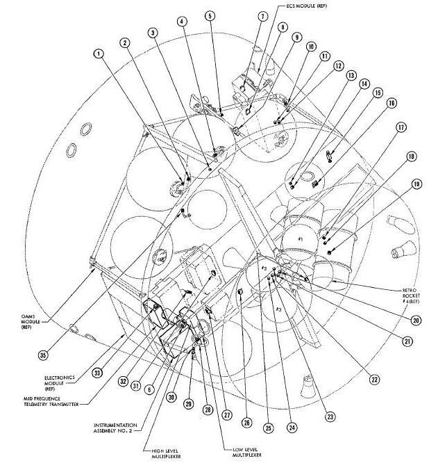
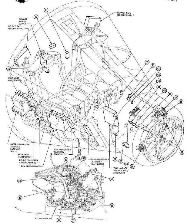
The basic components comprising the Instrumentation System are: sensors, signal conditioners, Multiplexer-Encoder System, and transmitters. Because the system is used to sense Parameters of every spacecraft system, its components are located throughout the spacecraft as shown in Figure below.
Instrumentation System Components
The purpose of the Instrumentation System is
data acquisition with respect to the progress and condition of the
spacecraft, necessitating its operation throughout the mission. The
Instrumentation System provides the capability of data acquisition and
transmission to the ground stations. The data is supplied by all
spacecraft systems. The basic operations by which the system fulfills
its purpose are: to sense the various conditions and functions; convert
them to proportional electrical signals (if applicable); condition the
resulting signal (when necessary) to make it compatible with the
encoding and multiplexing equipment; display pertinent data in the
cabin; record data for delayed time (datadump) transmission; and provide
signals for real-time transmission to the ground
station. An overall block diagram of the Instrumentation System is shown
in
Figure Below and the power distribution is shown in
Figure Below.
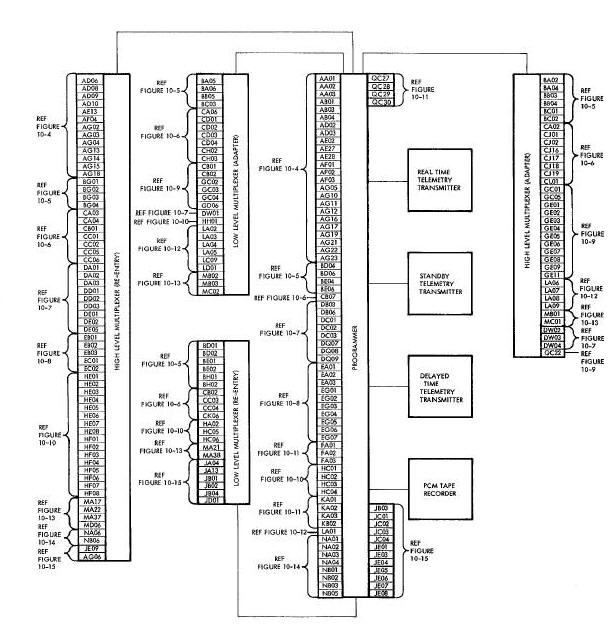
Instrumentation System Signal Flow Block Diagram
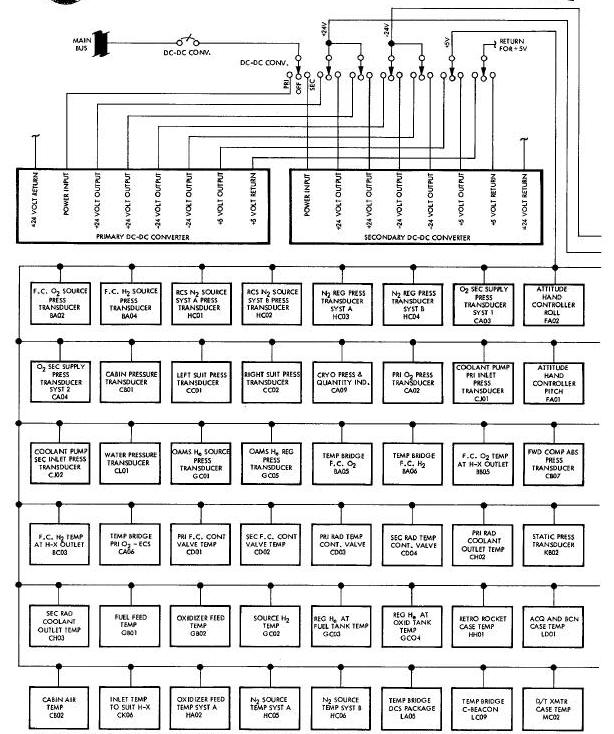
Instrumentation System Power Control Circuitry Functional Diagram
The system senses the prescribed parameters through the use of sensors which may be contained within the Instrumentation System or which may be an integral part of another system. Typical sensors include pressure transducers, accelerometers, and temperature sensors. Signals may also be obtained from such functions as switch and relay actuations, and from electronic package monitor points. Sensors and signal sources are shown in block diagram form on the applicable data source system illustration.
The majority of the signals acquired are usable for the spacecraft cabin indicators and/or the encoding equipment without alteration. Some of them, however are routed to signal conditioning packages (instrumentation assemblies) where their characteristics and/or amplitudes are changed. The resulting signals, as well as those from the other sensors, are of four basic types: low-level (0-20 my tic),high-level (0-5 vdc), bi-level (0 or 28 vdc), and hi-level pulse (28 or 0 vdc). Signals of selected parameters are supplied to the cabin indicators, while signals of all parameters are supplied to the Multiplexer/Encoder System. The Multiplexer/Encoder System converts the various spacecraft analog and digital signals to a serial binary-coded digital signal for presentation to the data-dump tape recorder and the real-time telemetry transmitter. The tape recorder records a portion of the real-time data from the program at a tape speed of 1 7/8 inches per second and, upon command, will play back the data for transmission to a ground station, at a speed of 1.25 ips (22 times the recording speed).
Four physiological functions are monitored for each pilot. All of the measurements are supplied as real-time data, while only one is supplied as delayed-time data. In addition, most of the measurements are recorded by two special (biomed) tape recorders.
During pre-launch operations, data acquisition is accomplished by use
of hardlines attached to the spacecraft umbilical and by telemetry.
Between launch and orbital insertion, data acquisition is via the
real-time telemetry transmitter. While the spacecraft is in orbit, data
is acquired via the realtime telemetry transmitter for the period while
the spacecraft is within range of a ground station. Data during the
period while the spacecraft is out of range of a ground station is
recorded On the PCM recorder and played back via
the delayed-time telemetry transmitter while the spacecraft is within
range of a ground station. A more detailed description of the telemetry
transmitters is given in
the Communication Section.
The paragraphs to follow, present a brief description of all instrumentation parameters. The parameters are described in groups identified by their applicable data source system. It should be noted that although most of the parameters are applicable to all spacecraft, the following parameters is for spacecraft 8 specifically.
A functional diagram showing the Sequential System parameters is presented in Figure Below. The Instrumentation System monitors 41 sequential events and Sequential System parameters. Each parameter is described below individually, or as part of a group of related parameters.
Sequential System Parameters Functional Diagram
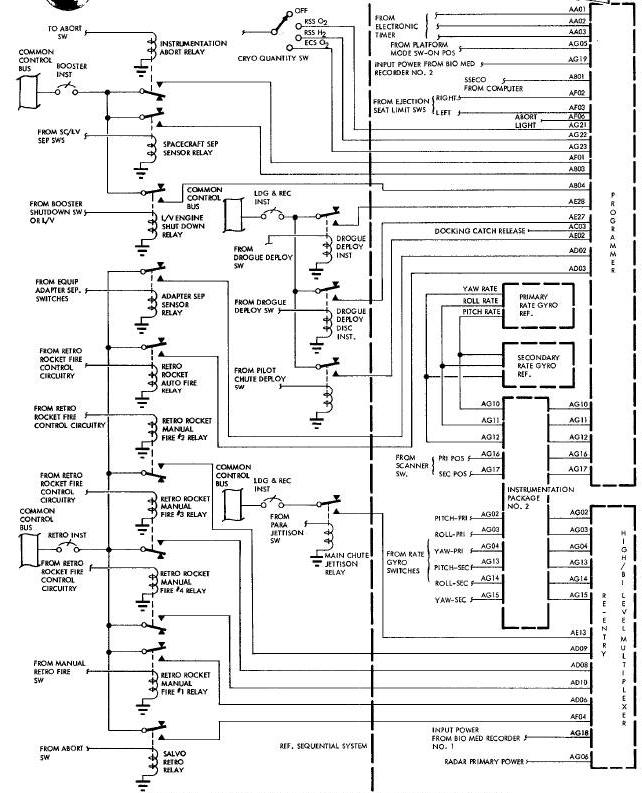
The Time Reference System (TRS) supplies three 24-bit digital words to the 24-bit shift register of the PCM programmer. These three signals are: time since liftoff (AA01, AA02) and time to retrograde (AA03). Time since lift-off is referenced to the launch vehicle lift-off signal and provides time correlation for the data tape recorders. Time to retrograde (MO8) indicates the time remaining before retrofire initiation by the TRS. This signal is used to verify that the correct retrofire time has been inserted into the TRS by ground command or by the pilots.
Lunch vehicle second stage cut-off (ABO1) is monitored for ground station indication of this event. This parameter is provided by a signal from the spacecraft IGS computer to a bi-level channel of the programmer.
Launch vehicle/spacecraft separation (AB03) is indicated to the ground station when any two of the three spacecraft/launch vehicle limit switches close, energizing the spacecraft separation relays. Actuation of any two of the three relays applies 28 vdc to a bi-level channel of the programmer.
The retrorocket ignition commands are monitored by ground stations to obtain data for calculation of expected re-entry trajectory. Automatic (ADO3) and manual (ADO6) ignition commands are monitored. Parameters are obtained from the ignition command of the four retrorockets individually; ADO9, rocket 2; ADO8; rocket 3; ADIO, rocket 4. The manual and automatic retrofire commands indicate retrorocket I fire. The signals, 28 vdc, are applied to the re-entry high-level multiplexer.
Channel 10 of the Digital Command System is used by the ground station to relay the abort command to the spacecraft. Verification of ABORT light Illumination is by (AF06) parameter.
Indication that the pilot actuated abort (AFO1) is supplied to the ground station. The signal is originated when the abort handle is moved to the ABORT position actuating a limit switch which energizes the instrumentation abort relays. Actuation of one of the relays applies a signal to a hi-level channel of the programmer.
In case of pilot ejection during an abort, left (AFO3) and right (AFO2) ejection seat gone signals are relayed to the ground station. The signals are originated at the time the ejection seats leave the spacecraft closing the corresponding limit switch and applying the signals to the bi-level channels of the programmer.
Confirmation of salvo retrofire is given to the ground station in case of an abort. A signal is applied to a hi-level channel of the re-entry high-level multiplexer when the salvo retrograde relay is energized.
Indication of booster cut-off command (ABO4) is given to the ground station when pilots move the ABORT handle to the SHUTDOWN position, actuating a limit switch. This energizes a relay applying 28 vdc to a bi-level channel of the programmer.
Ground indication of pilot parachute deployment (AE02) is provided via a bi-level channel of the programmer. The signal is originated when a lanyard from the parachute actuates a toggle switch, energizing the pilot parachute deployed instrumentation relay.
The parachute Jettisoned (AE13) signal is initiated when the pilot depresses the CHUTE JETT switch energizing redundant main parachute jettison relays. The relays apply a 28-vdc signal to a bi-level channel of the re-entry high-level multiplexer.
Platform mode selection (AG05) is indicated to a ground station. Any position other than OFF on the PLATFORM mode switch will apply a signal to a bi-level channel of the programmer.
Primary (AG16) or secondary (AG17) horizon scanner operation can be monitored by the ground station via bi-level channels of the programmer.
Primary pitch (AGO2), roll (AGO3), and yaw (AGO4) and second-v-j pitch (AG13), roll (AG14), and yaw (AG15), rate gyro operation is monitored to indicate an on or off condition. Each signal is applied to a signal conditioner whose output is applied to a hi-level channel of the high-level multiplexer.
Pitch (AG1O), roll (AG11), and yaw (AG12) rate gyro (primary or secondary depending which is operational) outputs are applied to three signal conditioners. Each of the signal conditioners is a transistor switch providing no output for an input of 0-0.325 volts and a 16. 5 volt output for an input greater than 0.325 volts. The conditioned signals are applied to bi-level input channels of the programmer.
Bio-medical tape recorder on-off signals (AGIS, AGI9) are used for time correlation of the recorded bio-medical data with the telemetry data. An on-off indication is provided to the playback recorder and to telemetry by a hi-level signal to the programmer (AG19) and re-entry high-level multiplexer (AG18). Drogue parachute deployment (AE27) and drogue release (AE28) can be verified by the ground station via hi-level channels of the programmer. The signals are initiated when the HI-ALT DROGUE switch is depressed.
The selected cryogenic quantity switch position is indicated to the ground station by AG21 (Reactant Supply System oxygen), AG22 (Reactant Supply System hydrogen), and AG2B (Environmental Control System oxygen) to allow the ground station to identify the reading of CA09 described under Environmental Control System.
ELECTRICAL POWER SYSTEM PARAMETERS
Figure Below shows a functional diagram of the Electrical Power System parameters. Approximately 24 Electrical Power System parameters are monitored by the Instrumentation System. The parameters are listed and described in the following subparagraphs.
Electrical Power System Parameters Functional Diagram
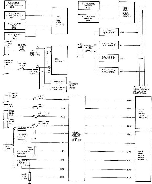
Fuel cell oxygen (BA02) and hydrogen (BA04) tank pressures are monitored by dual potentiometer pressure transducers installed as part of the fuel cell system. Each dual transducer provides one output to the adapter hlgh-level multiplexer and the other output drives an indicator on the instrument panel in the cabin.
To evaluate proper operation of the fuel cell, stack 1A (BDO1), 1B (BD02), 2A (BE01), 2B (BE02) and section I (BHO1) and 2 (BH02) currents are monitored and transmitted to the ground station. Stack C currents are obtained mathematically Electrical Power System Parameters Functional Diagram by subtracting section A and B currents from the corresponding section current. The signals being monitored originate from 50 millivolt shunts. The shunts are installed at the main buses for the section, and in the lines from stacks A and B to the main buses for stack A and B currents. Each of these signals is conditioned to a 0 to 20 millivolt signal which is directly proportional to the input current and then applied to the re-entry low-level multiplexer.
The following parameters relate to the ground station information regarding spacecraft main, squib and control bus voltages: BGO1 (main), BG02 (squib 1), BG03 (squib 2), BC (control bus). Each of these parameters is conditioned and then applied to the re-entry high-level multiplexer.
The Reactant Supply System (RSS) 02 (BA05) and H2 (BA06) supply bottle temperatures are monitored by means of two temperature sensors located on each supply bottle. The output of the sensors is applied to the adapter low-level multiplexer.
Fuel cell section 1 02 to H2 (BCO5), section 1 02 to H20 (BB07)3 section 2 02 to H2 (BOO6), and section 2 02 to H20 (BB08) differential pressures are monitored by a pressure-sensitive switch installed within the fuel cell to provide for safe operation monitoring capability of the fuel cell by the ground station. The outputs of the pressure switch is applied to hi-level channels of the adapter high-level multiplexer.
Oxygen (BB05) and hydrogen (BC03) temperatures at the outlet of the heat exchanger are monitored and relayed to the ground station via the adapter low-level multiplexer.
To provide an aid in evaluating fuel cell operation by the ground station, section 1 02 (BD04), section 2 02 (BE04), section 1 H2 (BD06), and section 2 H2 (BE06) purging is monitored. The signals are actuated by the pilot by placing the corresponding section purge switch to the H2 or 02 position. The signals are applied to the hi-level channels of the programmer.
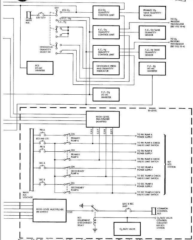
ENVIRONMENTAL CONTROL SYSTEM PARAMETER
A functional diagram showing the Environmental Control System (ECS) instrumentation parameters is presented in Figure Below. Twenty-eight parameters and RSS/ECS quantities associated with the ECS are monitored by the Instrumentation System and relayed to the ground station for analysis.
Environmental Control System Parameter Functional Diagram
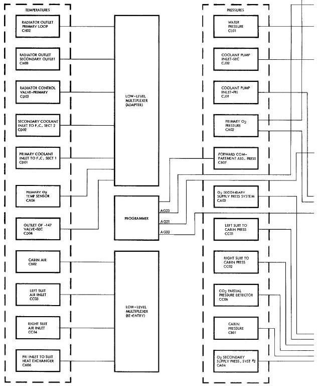
The primary oxygen tank pressure (CA02) is telemetered to the ground station and displayed in the spacecraft cabin. The signals originate from a dual potentiometer pressure transducer installed as part of the ECS. The signal is relayed to the ground station via the adapter high-level multiplexer.
A differential pressure transducer is used to sense cabin to forward compartment pressure differential (CBO1). The transducer has a dual output used for cabin indications and for transmission to the ground station via the re-entry high-level multiplexer.
Left (CCO1) and right (CC02) suit to cabin differential pressure is displayed in the spacecraft cabin and telemetered to the ground station. Dual potentiometer pressure transducers serve as the signal source. The output of each transducer is applied to the cabin indicator and to the re-entry high-level multiplexer.
The ground station is informed of an 02 high rate condition by COO5. This signal is originated when the spacecraft CABIN FAN switch is placed in the 02 HI RATE position, when manual 02 high rate is selected by the pilot, or when the suit pressure drops below 3-3 psia and 02 high rate is automatically selected. The signal is applied to a hi-level channel of the re-entry high-level multiplexer.
TO assure that a safe supply of oxygen is available to the pilots, CO2 partial pressure (C006) is monitored indicating the percentage of carbon dioxide with respect to the total pressure of gas in the suits. C02 partial pressure is displayed in the spacecraft cabin and applied to the re-entry high-level multiplexer.
Primary and secondary coolant temperatures are monitored at various locations within the coolant loop to evaluate system performance. Coolant temperatures are monitored at the primary coolant inlet to section 1 of the fuel cell (CDO1), secondary coolant Inlet to section 2 of the fuel cell (CD02), the radiator control valve in the primary loop (CD03), the secondary loop (CDO4), radiator outlet in the primary loop (CHO2), and radiator outlet in the secondary loop (CH03).
To relay information concerning proper operation of the coolant loop and pumps, to the ground station, primary (CJO1) and secondary (CJ02) coolant pump inlet pressures are monitored. The outputs of the transducers are applied to the adapter high-level multiplexer.
The condition of the primary and secondary coolant pumps is monitored by CJ16 (Primary Pump A), CJ17 (Primary Pump B), CJ18(secondary Pump A), and CJ19 (secondary pump B). The signal is originated when the corresponding coolant pump is actuated, and is applied to bi-level channels of the adapter high-level multiplexer.
To insure safe operation of the fuel cell, water pressure (CLO1) is monitored at the output of the fuel cell. The signal is applied to the high-level multiplexer.
The coolant inlet temperature to the suit heat exchanger (CKO6) is monitored to relay to ground stations information concerning the environmental condition of the pilots. The output of the temperature sensor is applied to the re-entry low-level multiplexer.
The position of the cryogenic quantity select switch is monitored to identify parameter CA09. The parameter CAO9 indicates ECS 02, RBS 02, or RSS H2 quantity depending upon the position of the cryogenic quantity select switch. The position of the selector swatch is indicated to the ground station by AG21 (F.C. 02), AG22 (F.C. H2), and AG23(ECS 02). The signals are applied to bi-level channels of the programmer. The parameter CAO9 is also applied to the programmer and is displayed in the spacecraft cabin.
Secondary 02 supply pressures are monitored in the number 1 (CA03) and number 2 (CAO4) systems. The transducers are installed as part of ECS secondary 02 supply assemblies. The outputs of the pressure transducers are applied to the re-entry high-level multiplexer.
As an aid in calculating ECS 02 quantity, the primary 02 supply
bottle temperature (CA06) is monitored and applied to the adapter
Low-level multiplexer. To provide the capability for the ground station
to monitor the environmental condition of the cabin and to provide an
aid for evaluating suit pressure, a cabin air temperature transducer
(CBO2), and a forward compartment absolute
pressure transducer (CBO7) is provided. Absolute pressure is applied to
the programmer and cabin temperature is applied to the re-entry
low-level multiplexer. Cabin temperature is also displayed in the
spacecraft cabin.
To further evaluate system performance and pilot environmental condition, the air entering the suit circuit Is monitored with respect to temperature by 2 dual temperature sensors (1 for each suit circuit). The temperatures are displayed in the spacecraft cabin and are applied to the re-entry low-level multiplexer as C003 (left suit), and CCO4 (right suit).
Figure Below shows a block diagram of the Inertial Guidance System
(IGS) parameters except the digital computer functions. The
Instrumentation System monitors 8 IGS parameters and handles
approximately 200 computer words.
Inertial Guidance System Parameters Block Diagram
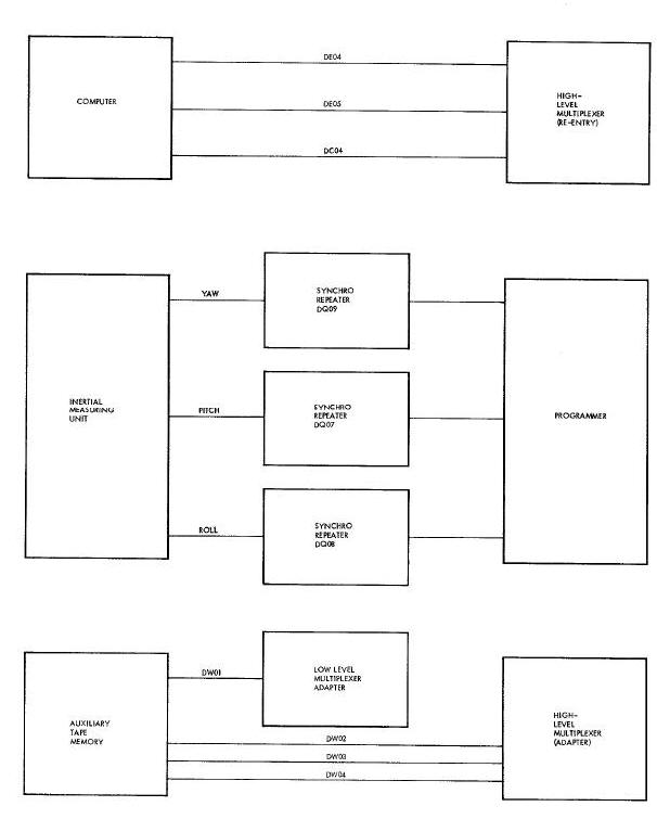
The Instrumentation System monitors the computer modes of operation; pre-launch, ascent, catch-up, rendezvous, re-entry, and touchdown. Important functions or parameters (approximately 200) are monitored during each mode of operation. This information is used during post mission analysis and is applied to the programmer.
In addition to the digital computer words, the Instrumentation System monitors the following IGS parameters.
Inertial platform attitudes are monitored to provide ground stations with attitude data during flight. Roll (DQ08), pitch (DQ07), and yaw (DQ09) signals are taken from the Inertial Measuring Unit (IMU), conditioned by synchro repeaters, and applied to the programmer.
IGS regulated power is monitored at two points : 26 vac (DE04) and 10.2 vdc (DE05). These voltages are conditioned and then applied to the re-entry high-level multiplexer.
Computer START light (DC04) malfunction signal is the only malfunction detection parameter monitored. This signal is used for display in the spacecraft cabin and applied to the bi-level channel of the programmer.
Auxiliary Tape Memory environmental conditions are monitored by case temperature (DWO1) and internal pressure (DW02). Motor drive inhibit (DWO3) and verification reproduction plus 20 volts (DW04) parameters indicate the mode of operation (off, standby, read, or write).
ATTITUDE CONTROL AND MANEUVERING ELECTRONICS PROGRAMMERS
A block diagram showing the Attitude Control and Maneuvering Electronics (ACME) System parameters is shown in Figure Below. Fifteen ACME parameters are monitored by the Instrumentation System.
Attitude Control & Maneuvering Electronics Parameters Block Diagram
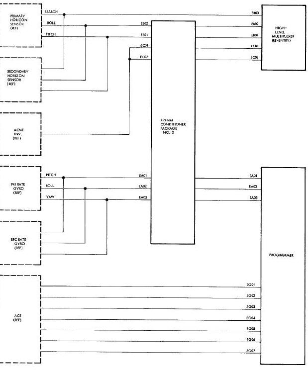
Spacecraft rates in pitch (EAO1), roll (EA02), and yaw (EAO3) are monitored to allow evaluation of the rate control portion of the ACME. Each signal from the rate gyro package is conditioned by a phase sensitive demodulator and then applied to the high-level channels of the programmer. Primary and secondary rate gyro signals are parallel summed and monitored on the same channels.
Horizon Sensor operation is monitored with respect to pitch (EB01) and roll (EB02) outputs, and search mode of operation (EB03). Pitch and roll parameters are monitored to verify inertial platform alignment for the retrograde phase of the mission. These parameters (EBO1, EB02) provide pitch and roll attitudes from the Horizon Sensor during orbital flight when the platform has been shut down to conserve electrical power. The signals originate when the SCANNER switch is in the PRI or SEC position. The pitch and roll outputs are conditioned and then applied to the re-entry high-level multiplexer. The search mode of operation is monitored to determine whether the Horizon Sensor unit is in the search mode, or has sensed the horizon. This signal illuminates the SCANNER light in the cabin and is also applied to a bi-level channel of the re-entry high-level multiplexer.
ACME inverter 26 vac voltage (EC01) and frequency (EC02) is monitored for post mission analysls. The signals are conditioned and then applied to the re-entry high-level multiplexer.
The following attitude control modes are monitored depending upon the position of the AITITUDE CONTROL switch; HOR SCAN (EG01), RATE CMD ORBIT (EG02), DIRECT (EG03), PULSE (EGO4), RATE CMD RNTY (EGO5), RE-ENTRY (EG06), and PLATFORM (EG07). The signals are applied to bi-level channels of the programmer.
ORBIT, ATTITUDE AND MANEUVERING SYSTEM PARAMETERS
The Orbit, Attitude and Maneuvering System (0AMS) parameters are shown in Figure Below in block diagram form. A brief description of each of the 19 parameters is given in the paragraphs to follow.
Orbit, Attitude & Maneuvering System Parameters Block Diagram
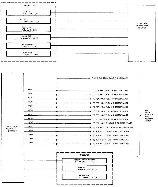
To insure that adequate propellant pressure is available for OAMS, helium source pressures (GCO1) is monitored. The signal originates from a duel potentiometer pressure transducer at the helium pressurant tanks. One output is applied to the adapter high-level multiplexer and the other is used to drive an indicator in the spacecraft cabin.
The propellant feed temperature at the fuel (GBO1) and oxidizer (GB02) feed lines is monitored to verify that propellant aboard is above freezing temperature and is available for use. The signals originate from two individual temperature sensors and are applied to the adapter low-level multiplexer.
To allow monitoring capability of the helium at the source temperature (GC02) a temperature sensor is installed on the helium supply line at the supply tank. The output is applied to the adapter low-level multiplexer. A separate sensor is installed to drive an indicator in the spacecraft cabin.
Temperature of the pressure regulated helium is monitored at the fuel (GO03) and oxidizer (GC04) tank inlet lines. The outputs of these temperature sensors is applied to the adapter low-level multiplexer. Two additional sensors are installed to drive indicators in the spacecraft cabin.
Regulated helium pressure (GC05) is monitored by a dual potentiometer pressure transducer. One of the outputs is applied to the adapter high-level multiplexer, and the other is used to drive a cabin indicator. Reserve tank pressure (GC22) monitors pressure available to the reserve fuel tank.
To provide an indication of maximum Thrust Chamber Assembly (TCA) temperature, TCA I0 (GD06) injector head temperature is monitored. This signal is applied to the adapter low-level multiplexer.
To provide ground station monitoring capability of TCA firing, the following TCA solenoid command signals are applied to hi-level channels of the adapter high-level multiplexer: GEO1 (TCA 1), GE02 (TCA 2), GEO3 (TCA 3), GE04 (TCA 4), GE05 (TCA 5), GE06 (TCA 6), GE07 (TCA 7), GE08 (TCA 8), GE09 (TCA 9, 1O), GE11 (TCA 11, 12),GE13 (TCA 13), GE14 (TCA 14), GE15 (TCA15), and GE16 (TCA16).
RE-ENTRY CONTROL SYSTEM PARAMETERS
Figure Below shows in block diagram form the Re-entry Control System parameters. Some 24 parameters are monitored by the Instrumentation System to provide for ground station observation of proper system performance.
Re-Entry Control System Parameters Block Diagram
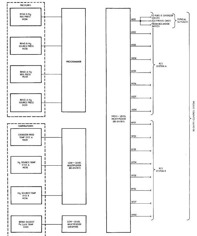
Nitrogen source pressure, HC01 (system A) and HC02 (system B), and nitrogen source temperature, HC05 (system A) and HC06 (system B) are monitored. Pressure is sensed by two dual pressure transducers. One of the outputs of each transducer is used to drive a cabin indicator, and the other is applied to the programmer. Outputs of the temperature sensors are applied to the re-entry low level multiplexer and are used to drive a spacecraft cabin indicator.
Because the oxidizer has a more critical temperature range than fuel, its temperature is measured to insure that both fuel and oxidizer are within the proper temperature range for use in the Re-entry Control System. The oxidizer feed temperature (HA02) is applied to the re-entry low-level multiplexer.
Regulated nitrogen pressure is monitored for system A (HCO3) and system B (HC04). The outputs of the pressure transducers is applied to the programmer.
To provide for ground station monitoring capability of proper RCS TCA firing, firing commands are applied to bi-level channels of the re-entry high-level multiplexer. RCS system A thrusters, 1A thru 8A have been assigned parameters HEO1 thru HEO8 respectively and system B thrusters IB thru 8B are designated by HFO1 thru HF08 respectively.
The retrorocket case temperature (HHO1) was monitored on spacecraft 5. The signal originated from a surface mounted temperature sensor located on retrorocket number 4 and was applied to the adapter low-level multiplexer.
AERODYNAMIC AND CREW CONTROL PARAMETERS
Aerodynamic and crew control parameters are monitored as shown in block diagram form in Figure Below.
Aerodynamic and Crew Control Parameters Block Diagram
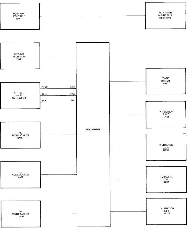
Spacecraft longitudinal (KAO1), lateral (KA02), and vertical (KAO3) accelerations are monitored to provide ground station indications during the launch and re-entry phases of the mission. The accelerometer outputs are applied to the programmer.
Static pressure (KB02) is monitored by a potentiometer type absolute pressure transducer. Static pressure is obtained from four static pressure ports equally spaced around the forward part of the conical section and connected in parallel to the transducer. The transducer output is applied to the programmer.
Pitch (FAO1), roll (FA02), and yaw (FADS) attitude control stick positions are monitored to indicate pilot manual control usage and to evaluate thruster operation. Signals originate from the attitude hand controller potentiometers and are applied to the programmer.
Two bi-level channels are reserved for events to be monitored as required by the experiments of each particular spacecraft mission. Electrical provisions for monitoring these parameters are provided at the right (FD01) and left (FEO1) utility receptacles.
COMMUNICATION SYSTEM PARAMETERS
The Instrumentation System monitors ll Communication System parameters. These parameters are shown in block diagram form In Figure Below. A brief description of each of the parameters is presented in the paragraphs that follow.
Communication System Parameters Block Diagram
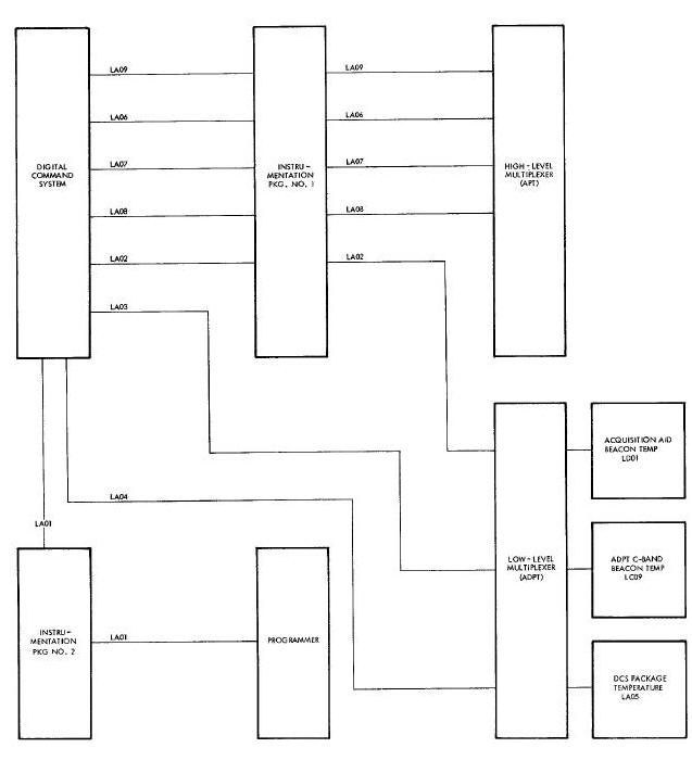
To verify proper DCS performance and aid in malfunction isolation, the following DCS parameters are monitored: diplexer (LAO4) and quadriplexer (LA03) receiver signal strength, package temperature (LA05), 6 vdc regulated power (LA02), 28 vdc regulated power (LA06), -18 vdc regulated power (LAO7), 23 vdc regulated power (LA08), and-6 vdc regulated power (LA09). Parameters LA02, LA06, LA07, LAO8, and LA09 are conditioned and then applied to the adapter high-level multiplexer except LA02 which is applied to the adapter low-level multiplexer. Parameters LAO3, LAO4, and LA05 are applied directly to the adapter low-level multiplexer.
Acquisition aid beacon (LD01) and adapter C-band beacon (LCO9) ease temperatures are also monitored to assure proper equipment performance. These temperature signals are applied to the adapter low level multiplexer.
INSTRUMENTATION SYSTEM PARAMETERS
To insure proper operation of the Instrumentation System, various
reference voltages and other pertinent data is telemetered to ground
stations for analysis. The Instrumentation System parameters are shown
in
Figure Below in block diagram
form. A brief description of each parameter follows.
Instrumentation System Parameters Block Diagram
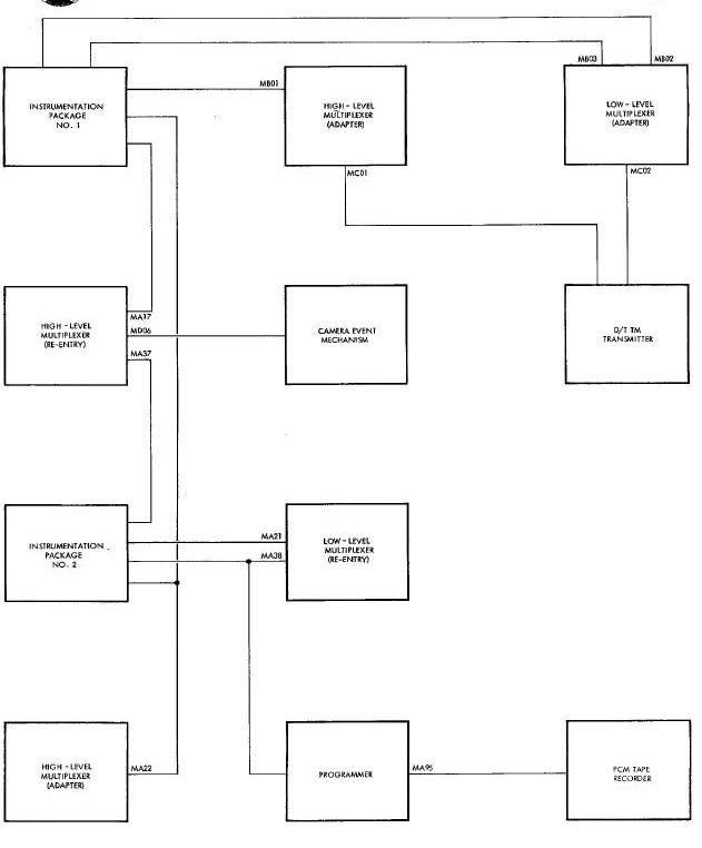
High (MA17) and low (MA38) level zero reference voltages are
monitored to insure that proper scaling is being employed by the
Multiplexer/Encoding System. The low-level zero reference originates
from the 5 vdc output of the dc-dc converter which is attenuated by a
signal conditioner to 3 millivolts (the zero reference point) and is
then applied to a channel in each of the
multiplexers in the re-entry vehicle. This signal is also applied to the
programmer as MA38.
High (MA37)and low (MA21) level full scale reference voltages, as the zero reference voltages, are required to insure that proper scaling is being employed by the Multiplexer/Encoding System. The 5 vdc output of the de-de converter is attenuated to 4.5 vdc and to 15 millivolts prior to application to channels of the high and low-level multiplexers in the re-entry vehicle, respectively. These parameters are required to provide a measurement of the reference voltage for potentiometer type transducers and resistive element temperature sensors.
Reference voltages for the high and low-level multiplexers located in the equipment adapter are provided by MBO1 (full scale) MB02 (zero) and MB03 (full scale). These have the same characteristics as the reference parameters described above.
Parameter MA22 (calibrate signal) is provided to indicate that a calibration voltage is being applied, thus eliminating the confusion between a data and a calibrate signal. Parameter MA22 will exist whenever the CALIB switch in the spacecraft cabin is actuated or a calibration is commended by the DCS.
An indication of proper functioning of the PCM tape recorder is provided by monitoring tape motion (MA95). This is accomplished by providing a signal to a bi-level channel of the programmer when the recorder tape reels are in motion.
The rf power output (MC01) and the case temperature (MC02) of the
delayed time telemetry transmitter is monitored to provide an indication
of transmitter operation. The transmitter physically located in the
adapter is chosen for these measurements because it is subject to more
extreme environmental temperature exchanges than the other two
transmitters. Temperature signals are applied to
the adapter low-level multiplexer, and the rf power output is applied to
the adapter high-level multiplexer.
A camera event (MD06) is indicated to the ground station when the pilot initiates the camera event mechanism on the onboard camera. This signal is applied to a bi-level channel of the re-entry high-level multiplexer.
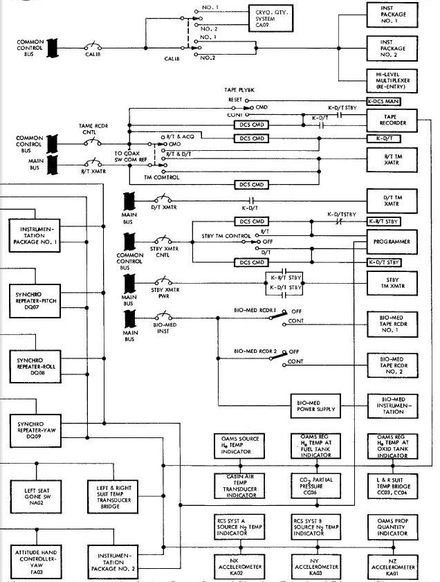
The physiological functions of the crew are monitored by sensors
which are attached at various points to their skin. A block diagram
showing the physiological parameters is shown in
Figure Below. Signal conditioners,
located in pockets of the underwear condition the signal from the
sensors to make them compatible with the recording and multiplexing
equipment. All parameters except the oral temperature are recorded on
bio-medical recorders. All signals, except oral temperature are applied
to the programmer. Oral temperature is applied to the re-entry
high-level multiplexer. The following command pilot parameters are all
monitored: electrocardiograms 1 and 2 (NAO1, NA02), respiration rate and
depth (NA03), and oral temperature (NA06). The following pilot
parameters are monitored: electrocardiograms 1 and 2 (NB01, NB02),
respiration rate and depth (NB03), and oral temperature (NB06). The
command pilot's blood pressure (NA04) and the pilot's blood pressure
(HB05) And suit inlet temperature (NB07) was monitored
on spacecraft 5 and 6 missions.
Physiological Parameters Block Diagram
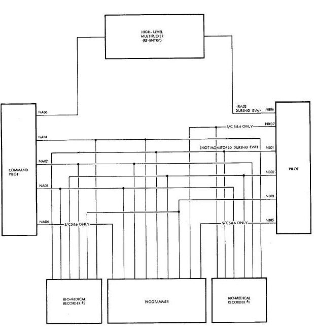
Electrocardiogram 1 (NBO1) is not monitored during Extra-Vehicular Activities (EVA). To allow the ground station to evaluate the pilot's environmental condition while outside the spacecraft, suit pressure (RA03) is monitored in place of oral temperature (NB06). All other physiological parameters are monitored as previously described.
To permit post-mission analysis of the Radar System operation during the rendezvous portion of the mission, 19 radar parameters are monitored. A functional block diagram of the radar parameters is shown in Figure Below.
Rendezvous Radar Parameters Block Diagram
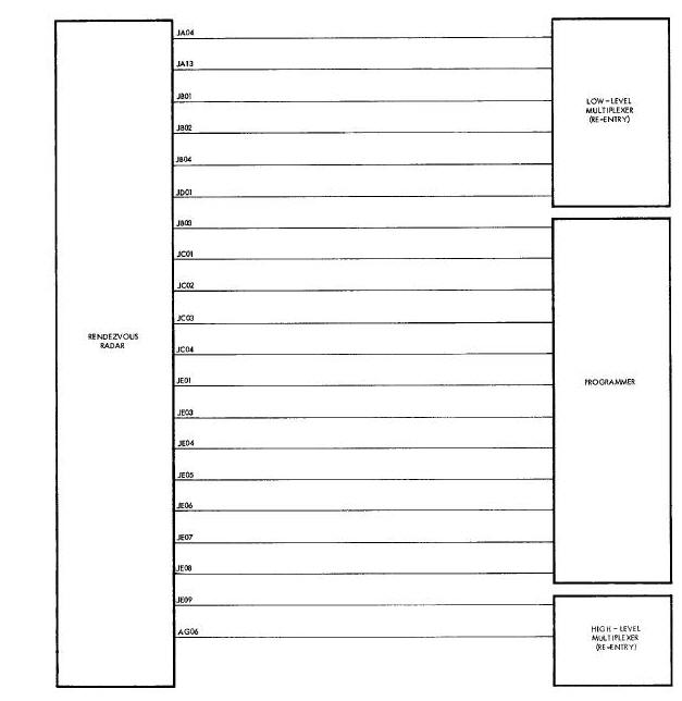
The target verification (JC04) parameter provides telemetry information that the spacecraft radar has located the target vehicle. The radar LOCK-ON indicator on the pilot's pedestal will illuminate when this event occurs. Target range rate (JA04) information is relayed to the ground station via telemetry transmission and displayed to the pilots on the range rate indicator. During rendezvous, the range to target (JA13) parameter provides close-rate data which is not available through the computer.
Radar inner skin (JBO1), antenna faceplate (JB02), and transmitter tube (JBO4) temperatures are sensed by resistive-element temperature sensors. A output which is proportional to the temperature sensed is produced by integral bridges within the sensor. A pressure transducer within the radar package senses radar pressurization (JB03). This signal is used to determine the validity of the radar operation, which is dependent on the internal pressure being maintained.
Oscillator crystal current (JC01) and radar regulated power (JEO1 and JEO3 through JE09) parameters provide information relative to the Radar System operation and monitor for specific functions which occur. Additional parameters monitored to evaluate the operation of the radar are: rf power (JC01), agc voltage (JCOR), and narrow-band agc voltage (JC03).
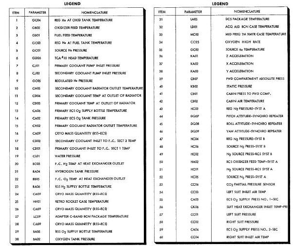
The purpose of the pressure transducer is to sense pressure, and to convert this pressure into a proportional electrical signal. There are six physically different configured pressure transducers as shown in Figure Below. Transducers have different physical appearances and different pressure ranges to accommodate the specific application of use. The numerical call outs below each transducer in Figure Below identifies the location and application of the transducer as shown in Figure Above. The numbers correspond to those on Figure Above .
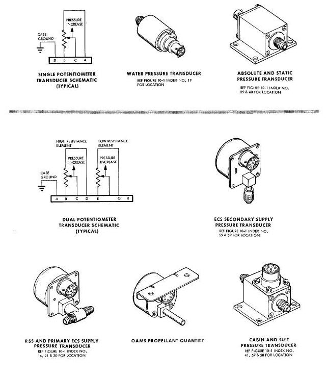
The sizes of the units vary from about 1 1/4 inches x 1 1/4 inches x 3 inches to 2 1/2 inches x R 1/2 inches x 4 inches; the weights vary from approximately 5 ounce to 1 pound. The unit construction utilizes a bellows or Bourdon tube which varies the wiper position of a potentiometer, proportionally, with the input pressure. Two potentiometers are used in the dual-output units to separate the cabin indicator circuit from the multiplexer/encoder (telemetry) circuit, thus avoiding a possible loading error in the latter. With one exception, pressure transducer outputs range from 0 to 5 vdc. The OAMS quantity system pressure-temperature sensor, driving a cabin indicator, has an output of 0 to 24 VDC.
Temperature sensors are used to convert temperatures into directly proportional electrical signals. Basically there are two types of temperature sensors: a probe type and a surface mounted type. Variations exist within each type to accommodate specific mounting requirements. Nine physically different types of temperature sensors are shown in Figure Below . With respect to temperature range, approximately 20 different sensors are used. The numbers beneath each sensor in Figure Below corresponds to the sensors locations and application as shown in Figure Above .
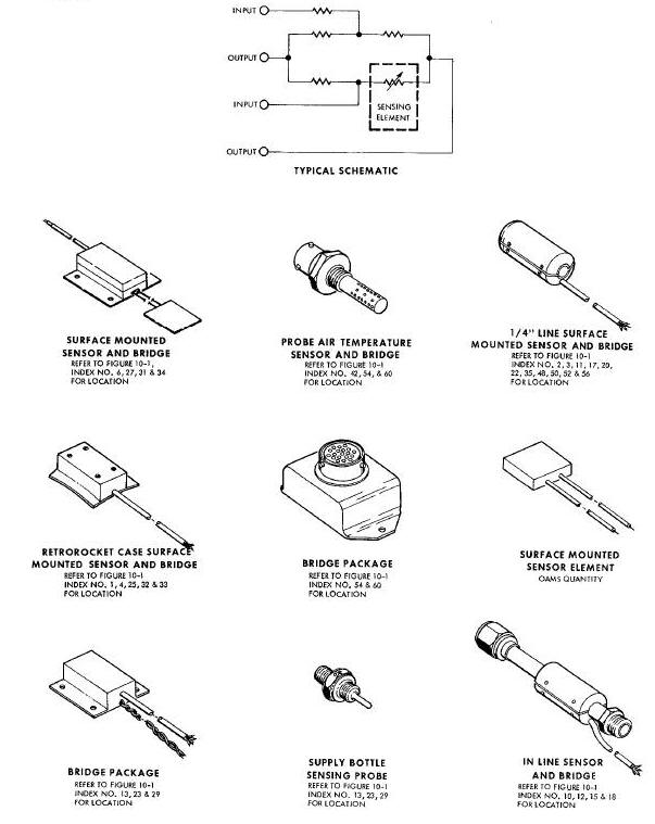
Spacecraft temperatures are monitored by platinum element temperature sensors. The sensors vary somewhat in size but are roughly 0.4 x 0.75 x 2.0 inches. There are two types of resistive-element sensors, a probe type and a surface-mounted type. Probes are used to monitor fluid temperatures, and surface-mounted sensors are used to monitor surface temperatures. Both types utilize a fully-annealed pure-platinum wire, encased in ceramic insulation. The sensors form one leg of a bridge network whose unbalance will produce an output of 0 to 20 mv dc or 0 to 400 my dc. The 0-20 mv dc outputs sre used for data transmission purposes and the 0-400 mv dc outputs for cabin displays.
In some applications, mounting and space requirements necessitate that the bridge is remotely located from the sensing element. In most cases, however, the bridge and sensing element are housed in the same case.
Regardless of how the bridge and sensing element are housed, combined, they comprise a schematic as shown in Figure Above .
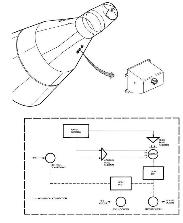
Three synchro repeater assemblies, mounted
in the upper portion of the aft landing gear will as shown in
Figure Below, monitor the synchros on the IGS platform gimbals. Each
synchro repeater output is adc signal proportional to the spacecraft
roll, yaw and pitch attitude in terms of platform coordinates. Two
outputs are available per repeater; a course output, which provides 0-5
vdc output for
0-350 degrees of synchro travel and a fine output, which gives 0-5
output for every 35 degrees of synchro travel; only the coarse output is
monitored as shown in
Figure Below. A dead band of i0 degrees maximum exists, centered
around the 135-degree position in the synchro repeater potentiometers.
Control of the synchro repeaters is achieved by pilot actuation of the
PLATFORM mode select switch.
Synchro Repeaters and Schematic Diagram
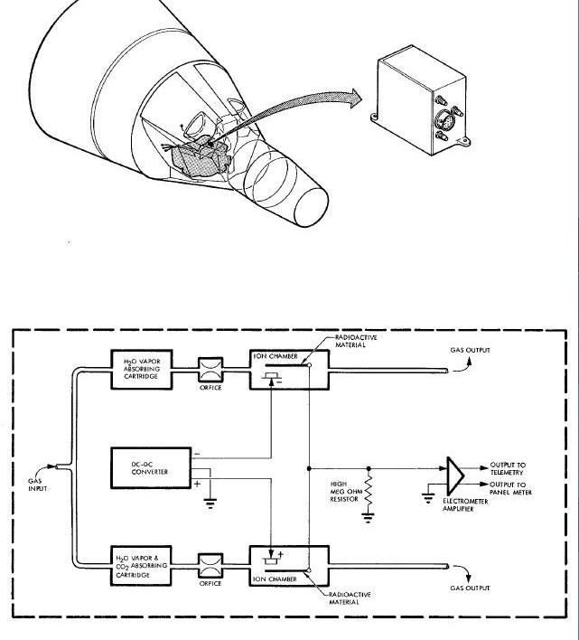
A carbon dioxide partial pressure detector, as shown in
Figure Below, is utilized to insure that there is a safe level of
C02 in the pilots suit circuits. The detector is located in the ECS
module. The gaseous mixture to be sampled is obtained as it exits from
the ECS carbon dioxide and odor absorbers. The sample stream is divided
through two separate passages, both filtering water vapor, but only one
filtering carbon dioxide. The streams then pass into identical ion
chambers which are polarized with + 50 vdc obtained from a dc-dc
converter contained in the detector assembly; there a radioactive source
ionizes the gases. The difference of the electrical outputs is amplified
and provides a voltage which is proportional to the partial pressure of
the mixture. The gas is then returned to the inlets of the suit
compressors. The system provides two outputs: O-5 vdc into a nominal 2.5
megohm load for telemetry use and 0-100 microamps into a 4000 ohm cabin
indicator.
C02 Partial Pressure Detector and Schematic Diagram
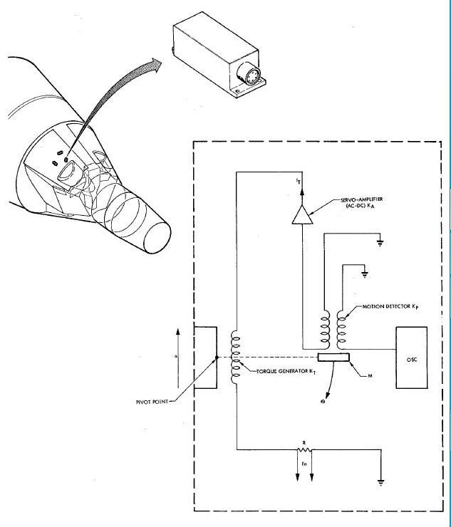
Three linear accelerometers are provided to measure the accelerations
along each of the spacecraft axes. The units are approximately 1.2 x 1.2
x B inches and are pictured in
Figure Below . The accelerometers
are electrically-damped, force balance, servo-type units with outputs of
0-5 vdc. The unit which is used for longitudinal measurements has a
range of -3 to +19 g and the other two have
ranges of -/+ 3 g. The accelerometer is a torque-balanced, closed-loop
system with a pendulous mass supported by an extremely low friction
Jewel bearing. The schematic of the accelerometer is shown in
Figure Below . An electromagnetic position detector notes the
slightest movement of the mass and supplies a directly proportional
electrical signal to a servo amplifier. The output of the servo
amplifier is applied to a torque generator which tends to restore the
mass to its equilibrium position. The output of the accelerometer is
obtained by sensing the voltage drop across the resistor in the system
loop.
Servo Accelerometer and Schematic Diagram
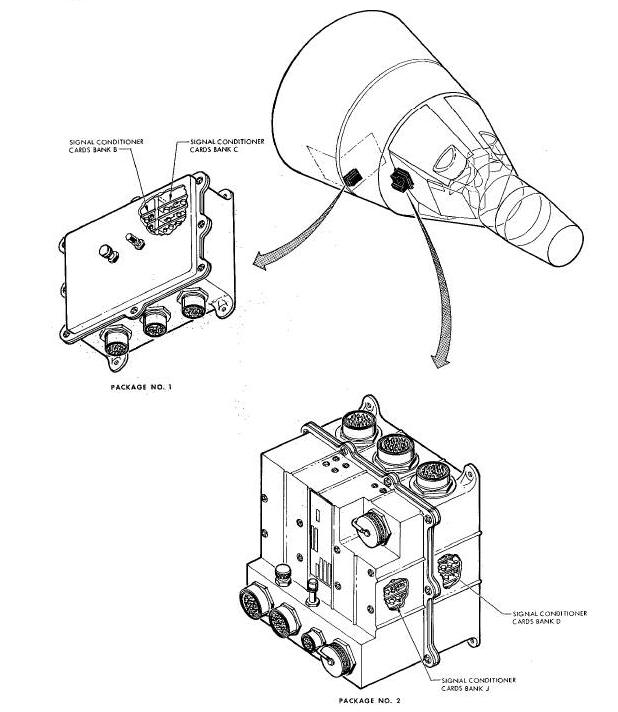
A number of the signals in the various spacecraft systems are not
compatible with the instrumentation circuitry, and therefore, must be
conditioned for their use. Two signal-conditioning packages
(instrumentation assemblies) are provided for this purpose.
Instrumentation assembly number i is approximately 8 x i0 x 3 inches and
is located in the adapter section. Instrumentation assembly
number 2 is approximately i0 x 10 x 8 inches and is located in the upper
right hand equipment bay of the re-entry section. Both units utilize
sealed containers with an operating pressure of 4.5 paid and are shown
in
Figure Guide . The assemblies employ a modular construction with
plug-in modules that may be replaced, individually. A module consists of
one or two standard printed circuit boards
with the necessary component parts and a connector for attachment to a
mother board within the package. There are 18 modules spaces in assembly
number 1 and 51 in assembly number 2. Some modules provide for one data
channel and others for two. There are six basic types of modules, and
several of these have additional variations for different signal
handling capabilities.
Instrumentation Package Assemblies
There are six variations of the Phase Sensitive Demodulators (PSD). Basically, the PSD accepts two input voltages: one signal voltage and one reference. It provides a dc output of five volts for a full scale input signal that is in phase with the reference and an output of zero volts for a full scale signal that is out of phase with the reference. The various configurations of this unit provide different full-scale sensitivities including special calibration curves for rate gyros.
The twelve types of dc voltage monitors are designed to accept various positive and negative dc voltage inputs and provide outputs of 0 to 5 vdc.
The ac voltage monitor accepts a signal ranging from 23 to 29 volts rms over a frequency range of 380 to 420 cycles. The output is from 0-5 vdc, varying only with the input voltage.
There are nine types of attenuator modules. These modules have various dc inputs which are changed to signals in the 0-20 my dc range or the 0-5 vdc range. Some attenuator modules contain two data channels.
The dc milllvolt monitor accepts an input of 0 to 50 mv dc and provides a proportional output of 0 to 20 my dc.
The ac frequency sensor provides a 0 to 5 vdc output proportional to an input frequency varying fro= 380 cps to 420 cps. The voltage level of the input is 26 volts rms and does not affect the output of the module.
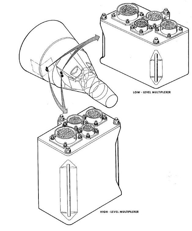
The multiplexer/encoder is divided into five packages to allow the
data signals to be sampled near their sources. Its purpose is to accept
signals from the signal pickups or signal conditioners, combine and
convert these signals to a serial binary-coded digital signal, and
supply this signal to the tape recorder and to the real-time telemetry
transmitter. The units are shown in their respective
locations in
Figures Below and
Figure Below.
Instrumentation System Multiplexers Diagram
Instrumentation System Programmer Diagram
The multiplexer/encoder consists of a programmer, two identical high-level multiplexers, and two identical low-level multiplexers. These five units are discussed as a single unit because of their close function relationship.
The low-level multiplexers each weigh 2.6 pounds and measure
approximately 5.75 x 5.25 x 2.75 inches. The high-level multiplexers are
5.25 x 4.75 x 2.5 inches and weigh approximately 3.25 pounds each. The
multiplexers might be considered as an expansion to the data handling
capability of the programmer and are dependent on the programmer for
encoding snd timing. The sampling rates of the multiplexer inputs are
established by the timing chain from the programmer. The low-level
multiplexers each sample 32 low-level (0-20 millivolts dc) signals: 24
at 0.416 samples per second and 8 at 1.25 samples per second. In the
high-level multiplexer, 32 high-level (0-5 vdc) are samples at 1.25
samples per second, and the 24 bi-level and 16 bi-level-pulsed signals
are sampled in sets of eight at a
sample rste of ten per second. For the bi-level signals, a binary one
(nominally 28 vdc, but at least 15 vdc) may indicate that an event or
function has or has not taken place. For example, the indication that
the bio-med tape recorders are on is a one but the indication that the
computer is on is a binary zero (nominally zero vdc, but less than 5 vdc).
For bi-level-pulsed signals, 15 vdc or more represents a binary zero,
while 5 vdc or less for at least ten milliseconds is a binary one. The
pulse conditioning circuitry in the multiplexer senses these pulses and
holds the voltage level until it is sampled by the programmer.
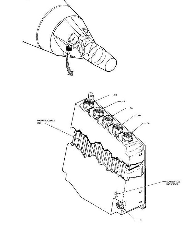
The programmer weighs approximately 20 pounds and measures approximately 11 x 11 x 4.5 inches. The programmer may operate as a self-contained data handling unit. The basic functions of the programmer are: data multiplexing; timing, to support the multiplexing functions; and analog to digital conversion. The programmer output is a PCM pulsetrain to the tape recorder and the real-time telemetry transmitter.
The basic components of the programmer are a high-level analog subcommutator, prime subcommutator, master commutator, analog to digital converter, output shift register, digital input circuitry and input selector, special timing, output filter, and the recorder input converter (Figure Below).
Multiplexer/Encoder System Block Diagram
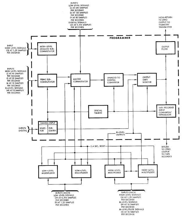
The programmer high-level analog subcommutator segment has the capability of sampling B2 high-level signal inputs at 1.25 samples per second. The analog subcommutator receives its inputs directly from the signal sources, or from the signal conditioners. The output of the analog subcommutator is applied to the prime subcoramutator for further multiplexing.
The prime subcormmutator, in addition to accepting the sampled high-level subcommutator data output, has the capability of sampling40 bi-level signals at 10 samples per second, 3 high-level signals at 40 samples per second, B highlevel signals at 20 samples per second and 6 high-level signals at 10 sampler per second. The prime subcommutator supplies its output to the master commutator.
The output of the master commutator is applied to the analog to digital converter where the analog output from the master commutator is converted to a digital presentation.
The digital data from the output of the analog to digital converter, digital input circuitry, and the two high-level multiplexers (bi-level signals) is combined in the output shift register into a continuous Non-Return-to-Zero (NRZ) Pulse Code Modulated (PCM) wavetrain of 51.2 kilobits per second.
The output of the output shift register is applied to the real-time telemetry transmitter, and to the tape recorder input converter/conditioner.
The tape recorder input converter/conditioner selects data from the 51.2 kilobits per second NRZ output of the output shift register, converts the data to an Return-to-Zero (RZ) output and applies the data to the tape recorder input conditioner module at 5.12 kilobits per second.
The serial outputs, provided from the programmer, all have positive
voltages for ones and zero or negative voltages for zeros. The output
for the tape recorder is a 5.12 kilobit per second serial Return-to-Zero
(RZ) signal with a +5 volt transition for data ones and a -5 volt
transition for data zeros. A clock signal at 5.12 kilobits per second is
also provided for the tape recorder. This output
is a pulse train of 50 percent duty cycle at a peak amplitude of 5
volts. The timing of the positive excursion is coincident with data one
pulses. The programmer output for the real-time transmitter is a 51.2
kilobit NRZ signal with a voltage which is adjustable between 0.I volt
and 1.0 volt peak. Separate hardline outputs are provided to allow
various test equipment to be used without degradation of the transmitter
or tspe recorder outputs. The hardline outputs are real-time PCM signal,
basic PCM clock rate signal, and master reset
pulse signal. The signals are two volts peak-to-peak and are fed over
twinex coaxial or video cables.
The programmer message format includes a master frame and prime
subframe; the complete format is transmitted as real-time and only the
prime subframe is tape recorded. The master frame consists of 160 words,
each word consisting of eight data bits, sampled 40 times per second.
Ninety-six master frames are required to completely cycle through all
data inputs. Every tenth word in the
master frame contains prime subframe data. The prime subframe consists
of 64 words sampled ten times per second. Twenty-four prime subframes
are required to cycle through all data inputs of this part of the
system. Information bits are obtained from analog data, arranged with
the most significant bit first, digital data, broken into groups of
eight bits with the most significant bit first, or bi-level data grouped
as eight consecutive data bits (referred to as a bi-level set).
Three telemetry transmitters are used to transmit the Instrumentation System data to the ground stations. Although the transmitters serve the Instrumentation System, its antennas, and associated switching is part of the Communication System; therefore, the transmitters are described in detail in Communication System.
The tape recorder is designed for monitoring and for producing a
recording of the signals received from the PCM programmer. The tape
recorder records PCM data at a tape speed of 1 7/8 inches per second and
playback, on command, of this recorded data, will, on command, stop,
reverse tape direction and playback the recorded data at a tape speed of
41.25 inches per second. Erasure of data
will occur only during record mode. The power control circuitry is
described in detail in Section IX, Communication System.
Telemetered signals recorded are RZ. The PCM tape recorder reproducer shown in Figure Aove consists of one completely enclosed tape recorder which is approximately 4.3 inches high, 10.0 inches wide and 10.0 inches deep. The tape recorder consists of the cover assembly, capstan drive assembly and tape transport assembly. Connectors on the side of the case assembly provide signal connections, power connections and test connections.
The magnetic tape recorder is capable of providing a minimum of four hours of recording time at a tape speed of 1 7/8 inches per second. Two tracks of simultaneous PCM data can be recorded at 1 7/8 inches per second. Four hours of RZ data at 5120 bits per second can be recorded at 1 7/8 inches per second.
Playback
On command, the recorder is to rewind the tape into the supply reel at
22 times the record speed (41.25 inches per second) while reading and
playing back the information recorded on the tape. Final output of
recorded data is in NRZ form.
The diphase signal processing technique permits the maximum tape utilization efficiency, while avoiding certain serious problems encountered with use of conventional NRZ recording at high packing density. It involves the encoding of the digital information prior to recording and decoding of the playback and conversion of the reproduced signal into standard NRZ form.
The diphase technique is essentially a phase-modulated carrier process. The digital data format to be recorded in RZ with an accompanying clock, and the desired output in the reproduce mode is of the standard NRZ form.
The diphase signal to be recorded is created in the following manner.
Inverted RZ data and clock signal are OR gated into a binary flip-flop
such that a transition of the flip-flop occurs on every negative going
edge. A logical zero is represented in the diphase code by a square wave
at 1/2 the data rate. Each time a logical one is received, a phase
transition occurs in the center of the bit cell so that a logic one is
represented by a square wave at the data rate. The output of the
flip-flop is the diphase signal. This signal is then fed to
the record amplifier which drives the diphase signal into the record
head.
During the record mode, the input signal is sent to a preamplifier, encoder and amplifier. A clock signal is applied to the input of the triggerable flip-flop. The diphase code produced is recorded on magnetic tape.
The magnetic tape is dc erased prior to recording. The magnetic head
utilized is a high-quality instrumentation recording head has a gap
width approximately 1/3 the recorded wave length. The gap width is not
critical, but if it is much wider than 1/3 of the recorded wave length,
the high frequency playback components are attenuated and if it is much
narrower, the high frequency components are
accentuated, causing a difficult equalization problem.
During the reproduce mode, the signal is picked up by the magnetic
head and applied to the playback amplifier, where it is amplified
approximately 60 db, filtered, and equalized to compensate for the
effects of the head to tape system. The equalized signal is then fed to
an input coupler where approximately 40 db of hard limiting is provided,
thus providing extremely high immunity from amplitude
variation in the reproduced signal.
The ability of this system to operate satisfactorily through such a large variation in playback signal amplitude assures a high degree of reliability and extremely low data drop out. The outputs of the input coupler, the recorded diphase signal and its complement, are fed to the one shot timing extractor circuitry and simultaneously to the decoder circuitry.
The function of the timing extractor and decoder is to produce timing pulses from the amplified and limited diphase playback signal. This circuitry detects the data, using the timing pulses and diphase signal, and produces the final NRZ output.
The output filter is fed the decoder output and filters out some of the higher harmonics of the NRZ output signal. The hardline output amplifiers produce a hardline output with good square wave characteristics at high frequencies.
DC-DC CONVERTERS
The two dc-dc converters (one of which is a standby unit) supply the
Instrumentation System with regulated dc power. The units are
approximately 5.5 x 5.5 x 7 inches weigh approximately seven pounds
each, and are located in the right-hand equipment bay of the re-entry
section as shown in Figure 10-25. The converters are essentially voltage
regulators which operate on 18 to 30.5 vdc and
supply output voltages of +5 vdc, +24 vdc and -24 vdc.
The power control circuitry for the dc-dc converters is shown in
Figure Above . Essentially, input power to the dc-dc converters is
supplied through the on position of the DC-DC CONV circuit breaker on
the overhead switch/circuit breaker panel. This arms the DC-DC CONV
switch. Placing the DC-DC CONV switch on the overhead switch/circuit
breaker panel, to the SEC or PRI position, will apply
power to the corresponding converter. Usage of the dc-dc converter
regulated output voltages is illustrated in
Figure Above.
BIO-MED TAPE RECORDERS AND POWER SUPPLY
The two tape recorders used in the
physiological Instrumentation System are identical. Each one is
approximately 9 x 6 I/2 x 1 3/4 inches (excluding connector and mounting
projections) and weighs about three pounds. One external connector
provides termination points for all inputs and outputs. The circuitry is
made up of 19 printed circuit boards with solid-state components. The
recorder
uses recording tape with a width of 0.497 + 0.001 inches. The reel
capacity is 880 feet. All physiological functions except oral
temperature and blood pressure of each pilot are recorded on the tape
recorders. Each recorder has six data channels and one timing channel.
The timing input is a pulse-coded pulsetrain derived from the Time
Reference System through the Time Correlation Buffer.
This signal is used for time correlation during post mission analysis. The recorders will operate for a total of 100 hours at a normal tape speed of 0.029S inches per second. Recorder operation is controlled by the crew during the mission without playing back the data. Upon completion of the mission, the recorders are removed from the spacecraft so thai the tape can be removed and the data extracted. The total power requirement of each recorder is 1.2watts at 24 vdc.
The electrical control circuitry for the bio-med instrumentation is shown in Figure Above and the location of the components is shown in Figure Above. The recorders are Government Furnished Equipment and are actuated from the spacecraft main bus through the BIO-MED INST circuit breaker and the CONT position of the BIO-MED RCDR switch (1 and 2).
ECS - Environmental Control System (ECS)
EVA - Extra-Vehicular Activities (EVA)
ips - Inches Per Second
IGS - Inertial Guidance System (IGS)
NRZ - Non-Return-to-Zero (NRZ)
OAMS - Orbit, Attitude and Maneuvering System (0AMS)
PCM - Pulse Code Modulated (PCM)
PSD - Phase Sensitive Demodulators (PSD)
rms - Root Mean Square
RZ - Return-to-Zero (RZ)
TCA - Thrust Chamber Assembly (TCA)
TRS - Time Reference System (TRS)
vac - Voltage Alternating Current
vdc - Voltage Direct Current